
Effects of Design Parameters on the Transmitted Torque of a Coaxial
Magnetic Gear with Halbach Permanent-Magnet Array
Yi-Chang Wu, Saian Nur Fajri
National Yunlin University of Science and Tecnology, Yunlin, Taiwan
Keywords: Magnetic Gear, Halbach Array, Transmitted Torque, Taguchi Method, Critical Parameter.
Abstract: The magnetic gear with Halbach Permanent-Magnet array can offer higher on transmitted torque compare to
radially magnetized permanent magnet and also capable of increasing the magnetic field. Then, the study of
this paper focuses on the effects of critical design parameters on the transmitted torque. Furthermore, the
magnetic field and the steady-state torque characteristic of Halbach type computed by commercial software
ANSYS/Maxwell. Under the use of Taguchi method, determined parameters in four levels, and focused on
five factors comprise the length of outer and inner rotor iron part, the length of outer and inner rotor
permanent magnet, and the length of pole pieces. Analysis result shows the optimum condition, the
percentage contribution of the design parameter using the ANOVA test, and the prediction torque was also
obtained. Finally, this paper shows the contribution of the outer and inner rotor permanent magnet with
0.35% and 15.53%. The radial length of the pole pieces contributed 3.21%. While the percentage of the
outer rotor iron part is 77.18%, and the inner rotor iron part does not significantly affect to the steady-state
torque, then it pooled. The estimated torque at optimum condition is 2179.55 Nm.
1 INTRODUCTION
The magnetic gear developed since 1941 (Fau,
1941). At that time, the magnet has two gears, and
the rotating axes are parallel to each other. Then,
Atallah and Howe (2001) discovered a new
magnetic gear type which still being developed until
now. The magnetic gear has a low-speed rotor, high-
speed rotor, permanent magnets and stationary steel
pole-pieces (Atallah and Howe, 2001). Generally,
the use of magnetic gear is to replace the functions
of mechanical gear. This idea based on the
disadvantage of mechanical gear and the advantage
of a magnetic gear. Mechanical gear has
disadvantages at risk of transmission failure
(because of the physical contact between the gears),
need periodic maintenance, generates friction and
vibration. Moreover, mechanical gear also at risk of
overheating. Overheating condition can destruct the
structure of the gear, and if the rotation speed is too
high, the gear teeth will be melted. In contrast,
magnetic gear can be a solution. Magnetic gear has
the advantage of transmitting power without
physical contact. The other advantages are no
vibration and noise, and no maintenance, and its
inherent overload protection (Atallah and Howe,
2001; Acharya et al., 2013; Uppalapati et al., 2014).
In the last ten years, industry and institution did
research and development about magnetic gear
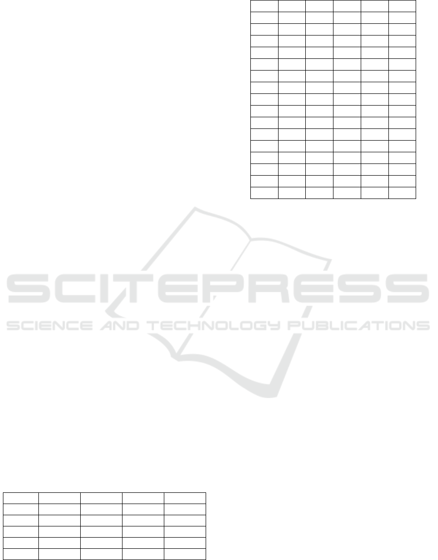
technology. From the research approach, shown in
Figure 1 is some publications about magnetic gear
accessed from web of science (2018). Those
institutions’ study not only about the characteristic
of magnetic gear, but also about the application of
magnetic gear. The researches about magnetic gear
characteristics, for example, investigates torque,
torque density, eddy current, pole piece shapes,
topologies, and noise-vibration. The examples of
magnetic gear application are for wind turbine, wave
energy conversion, geared-motor, vehicles
transmission, and so on. This topic is strongly
possible to reach steps for commercial application
(Wu et al., 2018; Li, K. et al., 2017; Liu et al., 2014;
Li, W. et al., 2017).
The most popular type of magnetic gear is
coaxial magnetic gear. Not only more accessible in
the manufacturing process, but this type also
produces higher transmitted torque than mechanical
gear. Using magnetic gear can produce a stable
transmitted torque when the rotor rotates at different
speeds (Neves and Flores, 2014). Beside coaxial
36
Wu, Y. and Fajri, S.
Effects of Design Parameters on the Transmitted Torque of a Coaxial Magnetic Gear with Halbach Permanent-Magnet Array.
DOI: 10.5220/0009006000360042
In Proceedings of the 7th Engineering International Conference on Education, Concept and Application on Green Technology (EIC 2018), pages 36-42
ISBN: 978-989-758-411-4
Copyright
c
2020 by SCITEPRESS – Science and Technology Publications, Lda. All rights reserved
type, there are other types which are radial magnetic
gear, transverse magnetic gear, worm magnetic gear,
planetary magnetic gear, rack and pinion gear, bevel
gear, and harmonic gear (Chen et al., 2014; Tlali et
al., 2014). Coaxial magnetic gear also has various
topologies for example radially magnetized, and
Halbach magnetized. Based on previous researches,
Halbach permanent-magnet array can offer higher
maximum torque. It also has lower torque ripple,
lower iron losses and also capable of increasing
magnetic field (Choi and Yoo, 2008; Jian et al.,
2009; Jian, 2010). It means that for transmitted
torque demand, Halbach arrangement is a good
choice to be developed. Finally, this study of this
paper focuses on the effects of Halbach critical
design parameters on the transmitted torque.
Figure 1: The publication on magnetic gears. (Source: web
of science).
1.1 Design Parameters
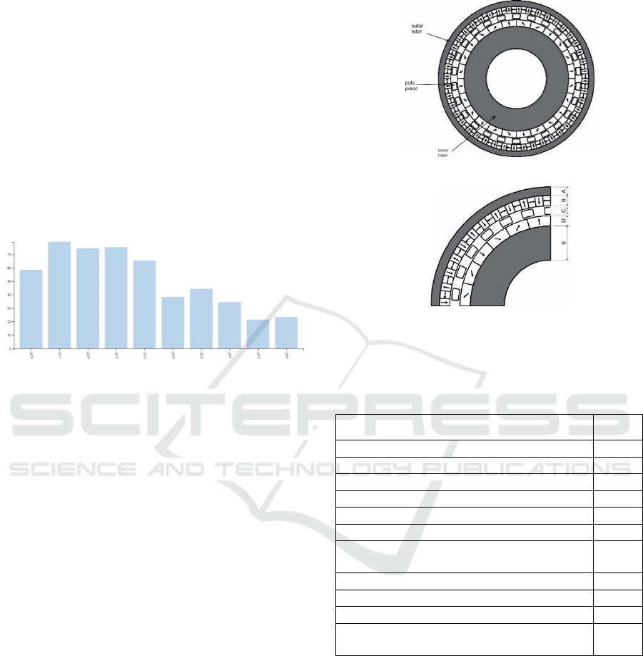
The Halbach permanent-magnet arrangement used in
this paper shown in Figure 2(a). As shown in Figure
2(a), the magnet direction in permanent-magnet
arranged by outward-concentrated magnetic field for
the inner rotor and inward-concentrated field for the
outer rotor.
Figure 2(b) shows the radial length of outer rotor
iron part coded as A. B defines radial length of outer
rotor permanent magnet. C and D in sequence define
radial length of pole piece and radial length of inner
rotor permanent magnet. The code E defines radial
length of inner rotor iron part. This codes (A, B, C,
D, and E) made as factors in this study. Then, these
parameters investigated by ANSYS/Maxwell
software.
The magnetic gear used in this research has
parameters shown in Table 1. This magnetic gear
has one input and one output. Under steady-state
condition, the simulation of magnetic gear needs to
be rotated in a reverse direction between input and
output. The input of this simulation is inner rotor,
and the output of the simulation is outer rotor. Using
2D ANSYS/Maxwell simulation, set two motion set
up to investigate the maximum torque produced by
the magnetic gear. The design parameters in this
study are identical with the previous research
(Mateev et al., 2016) shown in Table 1.
(a)
(b)
Figure 2: (a) Halbach permanent magnet array (b) Critical
design parameters.
Table 1: Design parameters of a coaxial magnetic gear
mechanism.
Parameter Value
N
umber of outer rotor pole pairs (P
o
) 26
N
umber of inner rotor pole pairs (P
i
) 4
N
umber of pole piece (z) 22
Diamete
r
of outer rotor (mm) 140
Diamete
r
of inner rotor (mm) 54
Ai
r
-gap length (mm) 1
Radial length of outer rotor iron part
(mm)
5
Radial length of outer rotor PM (mm) 6
Radial length of pole piece (mm) 4
Radial length of inner rotor PM (mm) 6
Radial length of inner rotor iron part
(mm)
20
Based on Table 1, had been shown the value of
parameters. The number of inner rotor pole pairs
(p
1
), outer rotor pole pairs (p
2
) and pole pieces (Ns)
defined by (1). The obtaining of pole pair number
effected to the gear ratio. The gear ratio of magnetic
gear used in this research is 5.5. The number of Gear
ratio (Gr) defined by (2). Otherwise, to simulating
gear rotation need to consider the rotation speed of
the input and output links. The rotational speed of
inner rotor (w
1
) defined by gear ratio and the
Effects of Design Parameters on the Transmitted Torque of a Coaxial Magnetic Gear with Halbach Permanent-Magnet Array
37
rotational speed of outer rotor (w
2
) as presented in
(3) (Kim et al., 2015).
During the simulation process using ANSYS/
Maxwell, the material for inner and outer rotor is
iron. The material for a permanent magnet is
NdFeB35. The material for pole pieces is Steel
1008. The objective of simulation is to gain the
transmitted torque in a steady-state condition. Inner
rotor and outer rotor rotate in reverse direction with
the amount 150 rpm and 27.27 rpm.
2 TAGUCHI METHOD
This research used Taguchi method which the use of
this experimental method allows examining under
various circumstances (factors). Taguchi Method has
three quality characteristics: nominal the best, larger
the better and smaller the better. Because of this
research investigated transmitted torque with an
unlimited number. Therefore the fit characteristic
was larger the better characteristic (Taguchi et al.
2005). Based on the previous explanation, the
factors for the research variable were factor A, B, C,
D, and E. The factors observed in 4 different levels.
The used of 5 factors and four levels were
demonstrated by Standard Orthogonal Array
L16(5
4
). These mean there were 16 various
experiments with five factors and four levels as
shown in Table 2 and Table 3.
The simulation processed based on the various
parameters shown in the Table 3. By using the
Taguchi Method, the observer could gather the
optimum condition, contribution each factor to the
result and estimate the result under the optimum
conditions. After investigating, the result analyzed
using Analysis of Variance (ANOVA), so the final
result would be established the percentage
contribution of each factor to the transmitted torque
(Taguchi et al., 2005; Roy, 1990).
Table 2: Factor and Level.
Facto
r
Level 1 Level 2 Level 3 Level 4
A 5 10 15 20
B 6 4 7 5
C 4 7 5 6
D 6 5 4 7
E 20 15 10 5
Table 3: Orthogonal Array.
A B C D E
1 5 6 4 6 20
2 5 4 7 5 15
3 5 7 5 4 10
4 5 5 6 7 5
5 10 6 7 4 5
6 10 4 4 7 10
7 10 7 6 6 15
8 10 5 5 5 20
9 15 6 5 7 15
10 15 4 6 4 20
11 15 7 4 5 5
12 15 5 7 6 10
13 20 6 6 5 10
14 20 4 5 6 5
15 20 7 7 7 20
16 20 5 4 4 15
3 RESULT AND DISCUSSION
Using ANSYS/Maxwell software obtain magnetos
tatic field and transmitted torque. The magnetostatic
field will be useful for future research assistant tool
in optimizing magnetic gear design (Wu, 2015). It is
related to increasing its field based on pole piece
shapes as well as permanent magnet arrangement.
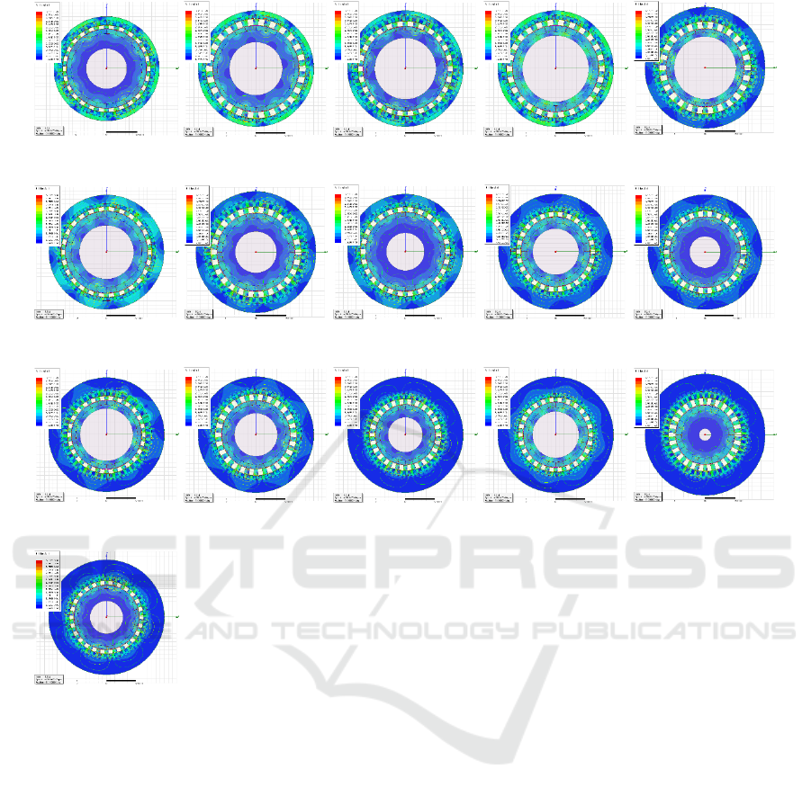
Figure 3 presents the magnetostatic field in angle
45
0
from 16 experiments. Magnetostatic field
presented in the same color scale which can be
compared to another experiment from the color.
Moreover, the value of the steady-state
transmitted torque shown in Table 4. This value then
shows the ability of every single magnetic gear
experiments to transmit power and torque. The table
also shows the signal to noise which measures the
sensitivity and external influencing factors, not
under control.
Based on Table 4, the transmitted torque in
optimum condition attains 2150.76 Nm which came
from experiment 4. The factors value in experiment
4 were level 1 for A factor and level 4 for another
factor. The lowest transmitted torque found in
experiment 16 which only 989.62 Nm. The factors
value in experiment 16 were level 4 for A and B
factor, level 1 for C factor, level 3 for D factor and
level 2 for E factor.
Ns = p
1
+ p
2
(1)
w
1
= -Gr w
2
(2)
w
1
= -Gr w
2
(3)
EIC 2018 - The 7th Engineering International Conference (EIC), Engineering International Conference on Education, Concept and
Application on Green Technology
38
(a) (b)
(c)
(d) (e)
(f) (g) (h) (i) (j)
(k) (l) (m) (n) (o)
(p)
Figure 3: Magnetostatic Field Analysis in (a) Experiment 1, (b) Experiment 2, (c) Experiment 3, (d) Experiment 4, (e)
Experiment 5, (f) Experiment 6, (g) Experiment 7, (h) Experiment 8, (i) Experiment 9, (j) Experiment 10, (k) Experiment
11, (l) Experiment 12, (m) Experiment 13, (n) Experiment 14, (o) Experiment 15, (p) Experiment 16.
After got the data shown in Table 4, the data
were analyzed to perceive the average performance
of the main effect on S/N and transmitted torque.
Because this research used higher the better
characteristic, so, based on Figure 4 can be
concluded that the optimum level by radial length of
outer rotor iron part is level 1. The optimum level by
radial length of outer rotor permanent magnet is
level 1. The radial length of pole pieces can affect
strongly in level 1. On the other hand, radial length
of inner rotor permanent magnet and inner rotor iron
part can perform better in level 4 and level 2.
Furthermore, the effects of research variable
analyzed using ANOVA down to percentage
contribution. The radial length of outer rotor iron
part factor has the highest percentage contribution
that is 77.92% followed by radial length of inner
rotor permanent magnet with 16.28%. Radial length
of outer rotor permanent magnet and radial length of
pole piece factors consecutively with 1.10% and
3.95%, while radial length of inner rotor iron part
factor affecting not significantly in the amount of
0.75%. Because it is under 1%, so this factor needs
to be pooled. Table 5 shows the result of ANOVA
analysis. The description symbols mentioned in
Table 5 are degree of freedom (f), Sum of Squares
(S), Variance (V), Variance Ratio (F), and
Percentage Contribution (P) in percent (%).
Effects of Design Parameters on the Transmitted Torque of a Coaxial Magnetic Gear with Halbach Permanent-Magnet Array
39
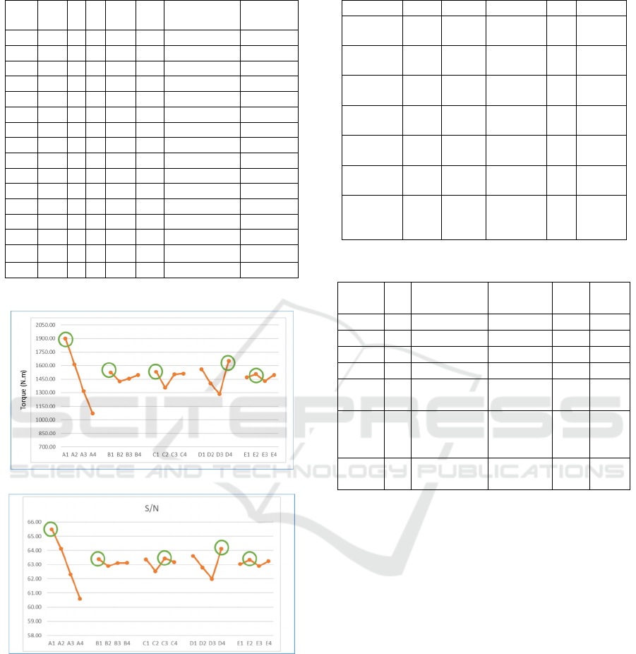
Table 4: The result of transmitted torque
.
A B C D E
Maximum
Torque
S/N
1 5 6 4 6 20 2081.7311 66.3685
2 5 4 7 5 15 1687.6924 64.5459
3 5 7 5 4 10 1667.5242 64.4414
4 5 5 6 7 5 2150.7576 66.6518
5 10 6 7 4 5 1373.1758 62.7545
6 10 4 4 7 10 1751.7327 64.8694
7 10 7 6 6 15 1747.7003 64.8493
8 10 5 5 5 20 1580.9525 63.9784
9 15 6 5 7 15 1599.5511 64.0800
10 15 4 6 4 20 1106.7157 60.8807
11 15 7 4 5 5 1307.2708 62.3273
12 15 5 7 6 10 1255.7313 61.9779
13 20 6 6 5 10 1037.6316 60.3209
14 20 4 5 6 5 1156.4207 61.2623
15 20 7 7 7 20
1106.7295 60.8808
16 20 5 4 4 15 989.6207 59.9094
(a)
(b)
Figure 4: Plots of factors main effect.
After pooled, the percentage contribution turned to
77.18% for outer rotor iron part. The contribution
value was 0.35% for outer rotor permanent magnet
and 3.21% for pole pieces. Moreover, 15.53%
contribution was given by radial length of inner
rotor permanent magnet. Hence, the other
contribution (error) contributes 3.73%. Pooled
ANOVA table is shown in Table 6.
Table 5: ANOVA table
.
Factors f S V F P
A 3 153585
1.226
511950.41 77.92
B 3 21706.9
63
7235.6543 1.10
C 3 77895.3
50
25965.12 3.95
D 3 320800.
948
106933.65 16.28
E 3 14718.8
48
4906.28 0.75
All other/
error
0 0 0
Total 15 1970
973.3
35
100
Table 6: Pooled ANOVA table
.
Fac-
tors
f S V F P
A 3 1535851.23 511950.41 104.4 77.18
B 3 21706.96 7235.65 1.5 0.35
C 3 77895.35 25965.12 5.3 3.21
D 3 320800.95 106933.65 21.8 15.53
E
(3
)
14718.85 Pooled
All
other/
error
3 14718.85 4906.28 3.73
Total
1
5
1970973.34 100
Furthermore, to estimate the transmitted torque
under the optimum conditions, the data from Figure
3 used for the simulation. Every highest effect
calculated as parameters then obtained transmitted
torque with 2179.55 Nm This value had to be
confirmed with the simulation and obtained 2261.40
Nm transmitted torque. The magnetostatic field of
this optimum condition shown in Figure 5, and
Figure 6 shows the transmitted torque graphic.
EIC 2018 - The 7th Engineering International Conference (EIC), Engineering International Conference on Education, Concept and
Application on Green Technology
40
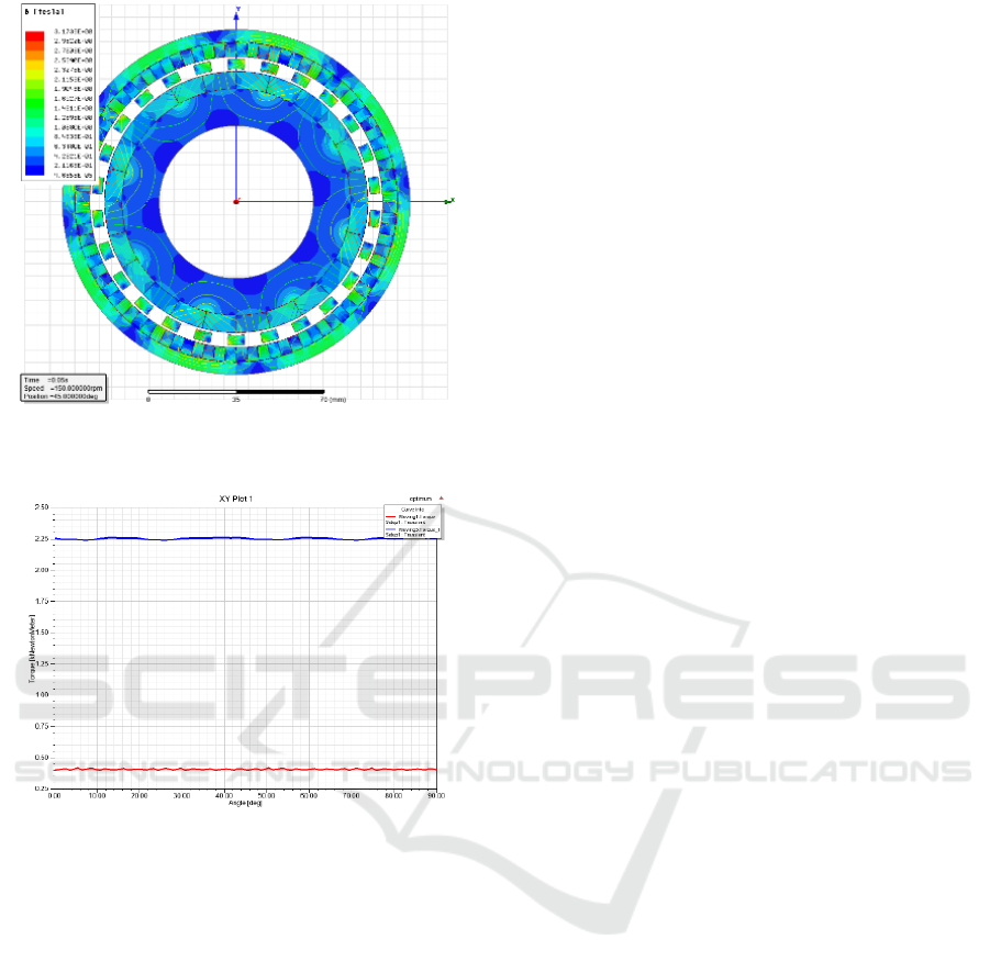
Figure 5: Magnetostatic Field in Optimum Condition.
Figure 6: Steady-State Torque in Optimum Condition.
4 CONCLUSIONS
In the case of this research, the effects of critical
design parameter to the magnetostatic field and
transmitted torque had been obtained. By using
Taguchi method, the transmitted torque in optimum
condition, percentage contribution of research
variable (factors) and estimate torque in optimum
condition had been presented. This research will be a
useful assistant to design coaxial magnetic gear with
transmitted torque demand by considering the radial
length of the critical design parameter. The best
parameters in this research are 5mm for radial length
of outer rotor iron part, 6mm for radial length of
outer rotor permanent magnet, and 4mm for radial
length of pole pieces. Furthermore, the radial length
of inner rotor permanent magnet and inner rotor iron
part are 7mm and 15mm. Future work on this study
will investigate the effects to the flux density, iron
losses, torque ripple and efficiency of coaxial
magnetic gear and solve the problem about
manufacturing Halbach magnetized type.
ACKNOWLEDGEMENTS
The authors are grateful to the Ministry of Science
and Technology (Taiwan, R.O.C.) for supporting
this research under Grants MOST 107-2628-E-224-
002-MY3 and MOST 107-2622-8-006-015.
REFERENCES
Acharya, V.M., J.Z. Bird, & M. Calvin, 2013. A Flux
Focusing Axial Magnetic Gear. IEEE Transactions on
Magnetics 49(7): 4092-4095.
Atallah, K. & Howe, D., 2001. A novel high-performance
magnetic gear. IEEE Transactions on Magnetics
37(4): 2844-2846.
Chen, Y., W.N. Fu, S.L. Ho, an& H. Liu., 2014. A
Quantitative Comparison Analysis of Radial-Flux,
Transverse-Flux, and Axial-Flux Magnetic Gears.
IEEE Transactions on Magnetics 50(11).
Choi, J.S. & Yoo, J., 2008. Design of a Halbach Magnet
Array Based on Optimization Techniques. IEEE
Transactions on Magnetics 44(10): 2361-2366.
Fau, H.T., 1941. Magnet gearing. U.S. Patent No.
2,243,555.
Jian, L., 2010. Coaxial Magnetic Gear with Halbach
Permanent-Magnet Arrays. IEEE Transactions on
Energy Conversion 25(2): 319-328.
Jian, L., Chau, K.T., Gong, Y., Jiang, J.Z., Yu, C., & Li,
W., 2009. Comparison of Coaxial Magnetic Gears
with Different Topologies. IEEE Transactions on
Magnetics 45(10): 4526-4529.
Kim, S.J., C.H. Kim, S.Y. Jung,. 2015. Optimal Design of
Novel Pole Piece for Power Density Improvement of
Magnetic Gear Using Polynomial Regression
Analysis. IEEE Transactions on Energy Conversion
30(3): 1171-1179.
Li, K., J. Wright, S. Modaresahmadi, D. Som, W.
Wiliams, & J.Z. Bird., 2017. Designing the First Stage
of Series Connected Multistage Coaxial Magnetic
Gearbox for a Wind Turbine Demonstrator. IEEE
Energy Conversion Congress and Exposition (ECCE)
pp. 1247-1254.
Li, W., K.T. Chau, C.H.T. Lee, T.W. Ching, M. Chen, &
J.Z. Jiang., 2017. A New Linear Magnetic Gear with
Adjustable Gear Ratios and Its Application for Direct-
Drive Wave Energy Extraction. Renewable Energy
105: 199-208.
Liu, C.T., H.Y. Chung, & C.C. Hwang., 2014. Design
Assessments of a Magnetic-Geared Double-Rotor
Permanent Magnet Generator. IEEE Transactions on
Magnetics 50(1).
Effects of Design Parameters on the Transmitted Torque of a Coaxial Magnetic Gear with Halbach Permanent-Magnet Array
41

Mateev, V., M. Todorova, & I. Marinova., 2016. Torque
Transmission Characteristics of a Coaxial Magnetic
Gear. In: 19th International Symposium on Electrical
Apparatus and Technologies (SIELA), Bourgas,
Bulgaria, 29 May – 1 June 2016, pp. 1-4.
Neves, C.G.C., & Flores, A.F., 2014. Coaxial Magnetic
Gear Analysis and Optimization. In: 3rd International
Conference on Renewable Energy Research and
Applications, Milwaukee, WI, United States, 19-22
October 2014.
Roy, Ranjit K., 1990. A primer on the Taguchi Method.
New York: Van Nostrand Reinhold.
Taguchi, Genichi, Subir Chowdhury, & Yuin Wu (2005)
Taguchi’s Quality Engineering Handbook. New
Jersey: John Wiley & Sons, Inc.
Tlali, P.M., R-J. Wang, & S. Gerber., 2014. Magnetic
Gear Technologies: A Review. In: International
Conference on Electrical Machines (ICEM), Berlin,
Germany, 2-5 September 2014, pp. 544-550.
Uppalapati, K.K., W.B. Bomela, J.Z. Bird, & J.D. Wright.,
2014. Experimental Evaluation of Low-Speed Flux-
Focusing Magnetic Gearboxes. IEEE Transactions on
Industry Applications 50(6): 3637-3643.
Web of Science,. 2018. Magnetic Gear. Available at:
http://webofknowledge.com (accessed 11 September
2018).
Wu, Y.C., & Jian, B.S., 2015. Magnetic field analysis of a
coaxial magnetic gear mechanism by two-dimensional
equivalent magnetic circuit network method and
finite-element method. Applied Mathematical
Modelling 39(19): 5746-5758.
Wu, Y.C., M.C. Tsai, & C.T. Chan,. 2018. Creative
Mechanism Design of Magnetic Gears Integrated with
Continuously Variable Transmissions. Advances in
Mechanical Engineering 10(5): 1-8.
EIC 2018 - The 7th Engineering International Conference (EIC), Engineering International Conference on Education, Concept and
Application on Green Technology
42
