
The Comparation Study of Orbital Electro Motor Patent
IDP00201300116 with BLDC Motor Construction to the Force and
Torque of the Electric Motor
Rahmat Doni Widodo, Widya Aryadi, Ahmad Rozikin
Department of Mechanical Engineering, Universitas Negeri Semarang, Indonesia
Keywords: Orbital Electric Motor, BLDC Motor, Magnetic Simulation, Force, Torque
Abstract: This study aims to compare the force and torque generated between orbital electric motor patent
IDP00201300116 with BLDC electric motor. This research was conducted based on magnetic simulation
modelling method using software. Coil wire material using Copper: 5.77e7 Siemens with dimensional cross-
section area of 5x3 cm, iron core using Miscellaneous Steel Material 20PNF1500 with dimensional cross-
section area of 6x2 cm, and permanent magnet using Neodymium Iron Boron 28/23 material with dimensional
cross-section area of 6x2 cm. Simulations are carried out on six rotor magnet position stages which represent
the rotor rotation motion. The simulation results produce the greatest force data that can be generated by
orbital electric motor of 180 N compared to the greatest force of BLDC motor of 159 N, while the greatest
torque capable of being produced by orbital electric motor is 3.58 Nm compared to the torque produced by
BLDC motors of 2.79 Nm. The average force that can be generated by the orbital electric motor is 106.57 N
compared to the BLDC motor of 132.83 N, the average torque produced by the orbital electric motor is 1,619
Nm compared to the BLDC motor of 1,623 Nm. Based on these data, it can be concluded that the construction
of orbitals electric motor at certain test points produces greater force and torque than the BLDC motor, but
BLDC motors have a higher average force and torque.
1 INTRODUCTION
The use of electric motors as a generator of
mechanical motion is currently widely used, to
become the most popular energy conversion system
to produce clean mechanical energy. In the future, the
application of electric motors has a big challenge,
especially the development of electric motor
technology that can produce large power and large
torque efficiently. Many patents were created to make
this happen. The invention proposed by Douglas F.
McFarland US 4473763 A entitled "Solenoid motor",
describes a solenoid motor consisting of a crankshaft
with a number of selenoids surrounding it (Mc.
Farland, 1984). This invention uses translational
motion to rotate the crankshaft so that it is less
efficient. In addition the invention of electric motors
was also stated by Michael John Werson US Patent
5986376 A entitled "Brushless DC motors", which
consists of rotors made of permanent magnets and
stator with iron core and installed windings facing
each other with the rotor (Werson, 1999). This
invention is less capable of producing large torque
due to the direction of the magnetic field produced by
the stator to the rotor or vice versa not in the toroid
core of the magnetic field. This happens because the
location and direction of the stator winding does not
really circle the rotor.
In the construction of the electric motor that is
currently not able to produce large torque due to the
direction of the magnetic field produced by the stator
to the rotor or vice versa is not in the direction that
produces maximum performance. This happens
because the location and direction of the stator
winding does not really circle the rotor or vice versa.
Based on the weakness of the use of magnetic field
force in the types of electric motors that exist, the
researchers developed the concept of electrical orbital
motors where the rotor construction is right at the
center of the toroid magnetic field or in the center of
the coil so that the maximum output energy is
obtained. The concept of orbital electric motor has
been registered for patent by the State University of
Semarang in 2013 and has obtained a patent
Widodo, R., Aryadi, W. and Roziqin, A.
The Comparation Study of Orbital Electro Motor Patent IDP00201300116 with BLDC Motor Construction to the Force and Torque of the Electric Motor.
DOI: 10.5220/0009005600090014
In Proceedings of the 7th Engineering International Conference on Education, Concept and Application on Green Technology (EIC 2018), pages 9-14
ISBN: 978-989-758-411-4
Copyright
c
2020 by SCITEPRESS – Science and Technology Publications, Lda. All rights reserved
9

certificate in 2017 with a patent number ID
P00201300116.
Brushless DC motor (BLDC) is an electric motor
that consists of rotors and stators that have front
facing faces. One of the parts consists of a permanent
magnet that is arranged parallel in one axis and has
the same distance between one and the other. The iron
core is one of the surfaces that deal with magnets. Iron
cores are arranged in certain angles and have the same
distance. The wire coil is wrapped around the iron
core where when the windings flow with an electric
current with a certain amount, it will produce torque
which will rotate the rotor (Werson, 1999).
Illustration of BLDC magnet construction can be seen
in the following figure.
Figure 1: BLDC motor construction with permanent
magnet rotors.
The BLDC motor is a type of synchronous motor
because the magnetic field generated by the stator and
the magnetic field generated by the rotor rotates at the
same frequency (Y.S Jeon, 2000). In the brushless DC
motor, polarity reversal is performed by power
transistors switching in synchronization with the rotor
position. Therefore, BLDC motors often incorporate
either internal or external position sensors to sense the
actual rotor position (Madhurima, 2012). Theore-
tically BLDC motor is a constant torque machine but
torque ripple exists practically due to current ripple,
emf waveform imperfections and phase current
commutation to the electric motor. The effects of
torque pulsation in BLDCM are audible noise and
visible vibration in the high precision application
(Babu, 2017). Besides the torque ripple and vibration,
there are more disadvantages from BLDC motor as
shown at Table 1 below.
2 TEST METHOD
2.1 Orbital Electric Motor
This patent is a construction of an electric motor
system circuit that is able to optimize the relative
magnetic force between the stator magnetic field and
the direction of the rotor motion or vice versa. This
patent electric motor construction has a rotor that is
located inside the stator winding cavity, where in the
winding cavity there is a toroid magnetic field center.
Construction and performance is designed by using a
rotor in the form of a ring gear without a shaft. The
use of rotor construction without shaft allows the
windings to be perfectly formed around the rotor. To
get mechanical motion, the inner teeth of the rotor
ring are connected to the sun's gear. This sun gear
shaft is then used as an output in the form of
mechanical rotational energy. When the motor is
working, the ring gears orbiting on the sun gear, this
is why this patent is named orbital electric motor.
Orbital electric motor construction can be seen in the
following figure.
The principle of using the magnetic field center in
the coil as motion energy can also be proven in other
types of motors, including electric axial flux perma-
nent magnet machines (AFPM) and Tubular moving-
magnetic linear oscillating motors (TMML OM).
Axial flux permanent magnet machines become one
Stato
r
Core
Coil
Magne
t
Table 1. Advantages and disadvantages of different types of motors (Naser, 2016).
Motor Type
Advantage Disadvantage
BLDC High Power density, High efficiency
Limited speed range,High cost,
Hi
g
h stator core los at hi
g
h spee
d
Induction Moto
r
(IM)
High speed range, High reliability, Low
cost, Ri
g
idit
y
in hostile Environments
Low efficiency, Thermal problem at
hi
g
h spee
d
Switched
Reluctance Motor
(SRM)
Desirable torque speed characteristics,
High reliability, Low cost, Rigidity in
hostile Environments
High torque ripple and noise, Low
power density, Low efficiency
EIC 2018 - The 7th Engineering International Conference (EIC), Engineering International Conference on Education, Concept and
Application on Green Technology
10
type of motor that allows to achieve high motor
performance. AFPM motors have high energy, and
light weight. AFPM motor is very suitable to be
applied to the in wheel drive and also the in line drive
on electric vehicles (Emran, 2017). sTMMLOM is an
actuator that works linearly with a high alternating
frequency. The advantages of this tool are efficiency,
performance and simple structure so that it can be
applied to many uses. This tool works without using
a crankshaft so it has an efficiency of 20-30 percent
compared to an electric motor that works with the
principle of rota-tion on the compressor refrigerator
application (Xuensong,2018).
2.2 Simulation and Analysis
The method used in this study is finite element
analysis using software. Finite element analysis is
performed for getting torque, force and flux density
distribution waveforms in static condition. The most
used performance characteristics obtained from the
analysis (Emran, 2017). Testing parameters using
software are based on materials commonly used to
make electric motors. The parameters for testing
simulation using software are as follows.
Coil material : Copper:5.77e7
Siemens/meter
Distace : 5cm
Iron Core material : Miscellaneous Steel Material
20PNF1500
Magnet material : Neodymium Permanent
Magnet Material
Neodymium Iron Boron28/
23
Coil cros section size : Lenght 5 cm, width 3 cm
Magnet size : Lenght 6 cm, width 2 cm
Iron Core size : Lenght 6 cm thick 2 cm
Current : 2 A 60 hz
Testing simulation using software is represented
by single segment of the electric motor, consisting of
a permanent magnet as a moving part, and one pair of
coils and an iron core. To determine the change in
magnetic force that occurs in one segment of the
electric motor, it is simulated that the magnet motion
moves closer to the coil until it reaches the center of
the coil core, starting from step 1 of the magnet
position farthest from the coil, until step 6 the magnet
position in the center of the coil. The simulation was
carried out on two different electric motor
construction, namely BLDC motor construction and
motor Solenoid construction to be analyzed for the
results of the differences of the two motor
construction.
3 RESULTS AND DISCUSSION
3.1 Simulasi BLDC Motor
BLDC motor construction generally places the coil
and iron core on the center of the electric motor, and
places a permanent magnet on the outside of the
motor. This kind of construction allows the BLDC
motor to work without using a brush. BLDC motor
simulations are performed on single segment of the
electric motor consisting of a permanent magnet, coil
and iron core. Simulations were carried out on six
stages of magnetic motion from step 1 to step 6 to
simulate the motion of the electric motor rotor. The
results of magnetic force simulation using software
obtained at the following graph.
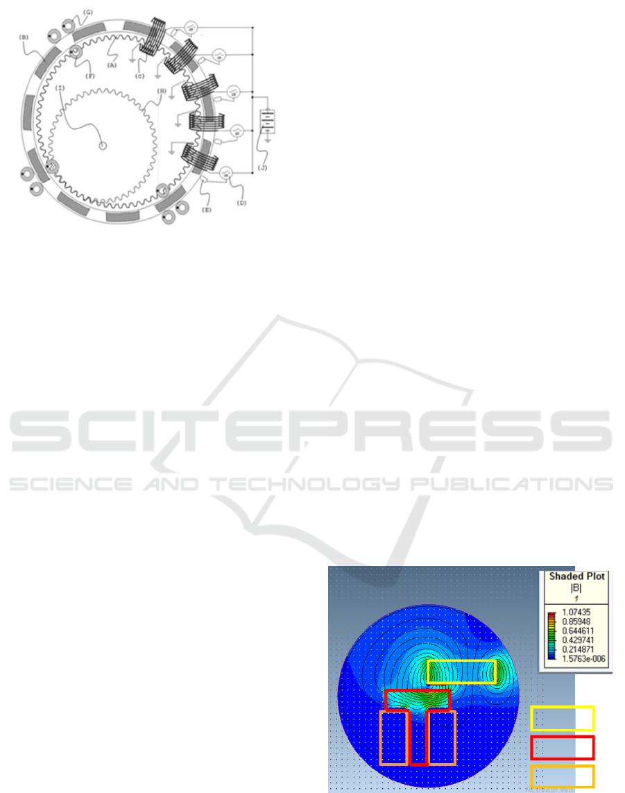
Figure 3: Magnetic flux simulations on BLDC motor
segments.
Magnet
Core
Coil
Figure 2: Orbital electric motor construction design.
The Comparation Study of Orbital Electro Motor Patent IDP00201300116 with BLDC Motor Construction to the Force and Torque of the
Electric Motor
11
Based on the illustration in Figure 3, it can be seen
that the magnetic force lines formed between the coil.
It create an attractive force to make the magnet
approach the magnetic center of the coil to produce
magnetic force and torque. The simulation results of
magnetic force and torque from different position of
the magnet from step 1 to step 6 are summarized in
Table 2 below
Based on the data shown in Table 2, the strongest
magnetic force simulation results are generated in
step 1 with a force of 159 N. The highest torque is in
step 5, which is 2.79 Nm.
3.2 Simulation of Orbital Electric Motor
Simulations on orbital electric motor use the same
method as simulations on BLDC motors. Simulations
on the orbital electric motor used only one motor
segment consisting of magnet, coil and iron core. The
three parts are made to have dimensions that are not
different from the BLDC type motor but have
different construction. Simulations on the motor
solenoid also use 6 stages of motion to simulate rotor
motion. The simulation results of the motor solenoid
construction using software can be seen from the
illustration of the following simulation results.
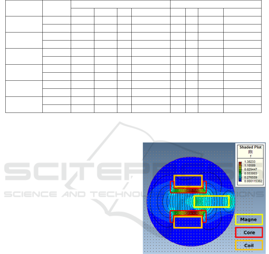
Based on the simulation illustration of the
magnetic force inf igure 4, the magnetic force line can
be seen in the middle between the upper and lower
coils which is very dense so that it is depicted in red
indicating a large magnetic force. It is used to draw a
permanent magnet which is positioned in the middle
of the coil so that a greater attraction is produced.
Detailed data from each stage of the simulation of
changes in magnetic position from step 1 to step 6 can
be seen in Table 3 below.
Figure 4. Magnetic flux simulations on orbital electric
motor segments.
Based on the data shown in the Table 3, it can be
seen that the greatest magnetic force generated is in
step 2 with a magnetic force of 180 N. The biggest
torque in the orbital electric motor simulation is
generated in step 1 with a torque of 3.58 Nm.
3.3 Comparative Analysis of BLDC and
Orbital Electric Motor
Based on the data in Table 4, BLDC motor has the
greatest force 159 N and the smallest force is 117 N
Table 2: Simulation of magnet position against magnetic force on the BLDC motor.
Simulation part
Force Torque
X Y Z Magnitude X Y Z Magnitude
Step 1
Coil 1 34 27.2 0 43.6 0 0 -0.883 0.883
Magnet -134 -84.8 0 159 0 0 2.3 2.3
Step 2
Coil 1 31.6 71 0 77.7 0 0 0.982 0.982
Magnet -69.5 -96.5 0 119 0 0 -1.78 1.78
Step 3
Coil 1 14.9 88.5 0 89.7 0 0 0.117 0.117
Magnet -65.5 -119 0 134 0 0 -0.591 0.591
Step 4
Coil 1 0.995 90 0 90 0 0 -1.45 1.45
Magnet -49.9 -142 0 150 0 0 0.765 0.765
Step 5
Coil 1 -9.67 97.5 0 98 0 0 -2.61 -2.61
Magnet 3.36 -118 0 118 0 0 2.79 2.79
Step 6
Coil 1 -18.8 84.4 0 86.4 0 0 -1.5 1.5
Magnet 6.95 -117 0 117 0 0 1.51 1.51
EIC 2018 - The 7th Engineering International Conference (EIC), Engineering International Conference on Education, Concept and
Application on Green Technology
12

with an average force value 132.8 N. The biggest
force produced by orbital elektric motor is 180 N and
the smallest force is 44.7 N with an average force of
106.6 N. The minimum torque produced by the
BLDC motor is 0.591 Nm and the greatest torque is
2.79 Nm with an average torque of 1.623 Nm. The
minimum torque produced by the electric motor
orbitals is 0.737 Nm and the greatest torque is 3.58
Nm with an average torque of 1,619 Nm.
Figure 5 shows that the force generated by the
BLDC motor tends to be stable with an average force
of 132.8 Nm. Orbital electric motor shows a graph of
unstable force with peak force with the lowest force
having a difference of 135.3 N with the pattern of
force on the orbital electric motor tends to decrease
when approaching the center of selenoid which
simulated in step 6
Table 3: Simulation of magnet position against magnetic force on the orbital electric motor.
Simulation Part
Force (N) Torque (Nm)
X Y Z Magnitude X Y Z Magnitude
Step 1
Coil 1 53 -46.5 0 70.5 0 0 -0.749 0.749
Coil 2 54 45.9 0 70.9 0 0 -1.38 1.38
Magnet -179 0.49 0 179 0 0 3.58 3.58
Step 2
Coil 1 51.5 123 0 133 0 0 0.155 0.155
Coil 2 52.9 124 0 134 0 0 -1.19 1.19
Magnet -180 6.84 0 180 0 0 2.09 2.09
Step 3
Coil 1 24.5 -168 0 169 0 0 -0.399 0.399
Coil 2 24.9 167 0 169 0 0 -0.325 0.325
Magnet -109 -0.002 0 109 0 0 1.63 1.63
Step 4
Coil 1 -5.64 -181 0 181 0 0 0.661 0.661
Coil 2 -5.67 180 0 180 0 0 -0.441 0.441
Magnet -44.7 0.137 0 44.7 0 0 0.889 0.889
Step 5
Coil 1 -31.5 -164 0 167 0 0 -0.101 0.101
Coil 2 -31.5 164 0 167 0 0 1.07 1.07
Magnet 47.9 -0.284 0 47.9 0 0 -0.737 0.737
Step 6
Coil 1 -43.3 -118 0 126 0 0 8.1 8.1
Coil 2 -43.6 118 0 126 0 0 -7.23 7.23
Magnet 78.8 -0.06 0 78.8 0 0 -0.789 0.789
Table 4: Comparative analysis of BLDC and orbital electric moto
r
.
Posisi
magnet
BLDC Orbital Motor
Force
Magnitude
(N)
Torque
Magnitude
(Nm)
Force
Magnitude (N)
Torque
Magnitude (Nm)
Step 1 159 2.3 179 3.58
Step 2 119 1.78 180 2.09
Step 3 134 0.591 109 1.63
Step 4 150 0.765 44.7 0.889
Step 5 118 2.79 47.9 0.737
Step 6 117 1.51 78.8 0.789
min 117 0.591 44.7 0.737
max 159 2.79 180 3.58
average 132.8 1.623 106.6 1.619
The Comparation Study of Orbital Electro Motor Patent IDP00201300116 with BLDC Motor Construction to the Force and Torque of the
Electric Motor
13

Figure 5: Comparison of BLDC and orbital electric
motor force.
Figure 6: Comparison of BLDC and orbital electric
motor torque.
Figure 6 shows that the torque generated by the
BLDC motor fluctuates with an average of 1.623 Nm.
The initial torque of the test on the orbital electric
motor is greater than BLDC motor, but the resulting
torque tends to decrease when approaching the
selenoid center which is simulated in step 6. The
maximum torque utilization in the electric motor
orbitals can be obtained by regulating the switching
of the solenoid current control.
4 CONCLUSION
Based on the comparison of simulation data using
software, the force generated by BLDC motor tends
to be stable with an average force of 132.8N while the
orbitals electric motor produce a fluctuating force
with an average 106.6 N. The torque produced by
BLDC motor fluctuates with the average value is
1.623 Nm while the torque on the Orbital electric
motor decreases with an average value of 1.619 Nm.
Orbital electric motor construction on single
electric motor segment produces a magnetic force and
torque greater than BLDC motor, this is based on the
analysis of BLDC construction resulting in a force of
159 N compared to the force produced by Orbital
electric motors of 180 N, while the greatest torque
BLDC motor is capable of producing 2.79 Nm
compared to the greatest torque of orbital electric
motor 3.58 Nm.
ACKNOWLEGMENT
The disseminating researchers were invited to the
Engineering Faculty of Semarang State University
which had supported the implementation of this
research through a study center's research fund
scheme at Engineering Faculty. Thanks to all parties
who have played a role in the completion of the
research.
REFFERENCES
Babu Ashok, Mahesh Kumar, 2017. Comparative
analysis of BLDC motor for Different control
topology. 1st International Conference on
Power Engineering, Computing and CONtrol,
PECCON-2017, VIT University, Chennai
Campus
Emrah Cetin, Ferhat Daldaban,. 2017. Analyzing
distinctive rotor poles of the axial flux PM
motors by using 3D-FEA in view of the
magnetic equivalent circuit. Engineering
Science and Technology, an International
Journal 1421–1429
Madhurima Chattopadhyay et al., 2012. Procedia
Technology 4. 666 – 670
Mc. Farland. 1984. Solenoid Motor. United States
Patent. US 4473763 A
Nasser Braiwish., 2016. Design Optimisation of
Brushless Permanent Magnet Synchronous
Motor for Electric Vehicles.Thesis. Cardif
University. United Kingdom
Werson, Michael. 1999. Brushless DC Motors.
Unites States Patent. US 5986376 A
Xuesong LUO, et al. 2008. 2018. Modeling and
analysis of mover gaps in tubular moving-
magnet linear oscillating motors. Chinese
Journal of Aeronautics, 31(5): 927–940
Y. S. Jeon, H. S. Mok, G. H. Choe, D. K. Kim & J. S.
Ryu, 2000. “A new simulation model of BLDC
motor with real back EMF waveform”, IEEE
CNF. On Computer and Power Electronics,
COMPEL
0
50
100
150
200
Step
1
Step
2
Step
3
Step
4
Step
5
Step
6
Force(N)
Bldc Orbitalmotor
0
1
2
3
4
Step1Step2Step3Step4Step5Step6
Torque(Nm)
bldc orbitalmotor
EIC 2018 - The 7th Engineering International Conference (EIC), Engineering International Conference on Education, Concept and
Application on Green Technology
14
