
Analysis and Design of Wireless Power Transfer
Syiska Yana, Emil Sinaga and Fahmi
Department Electrical Engineering, Faculty of Engineering, University of Sumatera Utara,Medan, Indonesia
Keywords: Wireless power transfer; energy technology.
Abstract: One of the most important basic needs of human life today is electrical energy, where the process of
shipping from a power source to the electrical load, in general, is still using the power cord. This paper
discusses Wireless Power Transfer, which is a way of transmitting electrical energy through the air media so
that electrical energy can be transmitted from a power source to an electrical load without using a conductor
or cable. The method used for wireless energy delivery systems is by using the principle of electromagnetic
resonance induction, which consists of a transmitter circuit and a receiver circuit. The effect of distance
between the transmitter and receiver is very influential. The maximum distance that the transmitter can send
to the receiver is 5 cm with a voltage of 1.3 volts.The farther the distance between the transmitter and the
receiver, the smaller the voltage will be, and the transmitted power will be smaller as well. Similarly, if the
distance between the receiver and transmitter is closer, the voltage, and power that can be emitted will be
even greater.The maximum power that can be generated from the transmitter circuit at the maximum
voltage of the adapter 15 volts at a distance of 2cm is 1.38 watts with a voltage of 2.76 volts.
1 INTRODUCTION
Along with the development of technology, we now
have developed electrical energy transfer system
without using cable.
Wireless Power Transfer is one way to transmit
electrical energy through the air media so that
electrical energy can be transmitted from a power
source to the load without going through a cable.
This development has an impact on the reduction of
cable usage because it can be replaced by Wireless
Power Transfer.
Wireless energy delivery technology was first
discovered and introduced by a physicist named
Nikola Tesla by building a tower named
Wardenclyffe Tower (Ahsan, 2015) shown in Figure
1. However, this study was discontinued for cost
reasons. Subsequent research on the delivery of
wireless energy was halted for decades until it was
re-developed by MIT researchers Marin Soljajic in
2007 who managed to transfer electrical power
without cables with a distance of more than 2 meters
and power of 60 watts, where the efficiency reaches
40 % (Kurs, 2007).Even in subsequent research, it
has been developed for the implementation of
Wireless Power Transfer system for transportation
system especially railway (Hwang, 2012).
The delivery of wireless electrical energy is a
method of sending electrical energy from a power
source to an electrical load without the use of a cable
intermediary. Generally, the Wireless Power
Transfer system consists of a series of Transmitters
and Receivercircuits.
Figure 1: Wardenclyffe Tower (Ahsan,2012).
36
Yana, S., Sinaga, E. and Fahmi, .
Analysis and Design of Wireless Power Transfer.
DOI: 10.5220/0008882000360040
In Proceedings of the 7th International Conference on Multidisciplinary Research (ICMR 2018) - , pages 36-40
ISBN: 978-989-758-437-4
Copyright
c
2020 by SCITEPRESS – Science and Technology Publications, Lda. All rights reserved

2 MATERIALS AND METHOD
There are two underlying concepts about the
transmission of electrical energy without cables,
namely the concept of near field and the concept of
far field (Stanimir, 2012). With a near-field method,
it is capable of transmitting electrical energy just
less than 1 meter while the concept of far-field
allows further distance delivery.
The delivery of electrical energy, as well as the
transmission of wireless information based on the
concept of far field, i.e., a laser beam (narrow beam)
and radio waves,is often used in the field of
telecommunications. Radio transmission is very
ineffective in the delivery of wireless electrical
energy because most of the radiated power delivered
is wasted into free air. To increase the amount of
energy that can be captured by the receiving side,
the power delivered from the sender side must be
large as well.
With the concept of direct radiation as shown in
Figure 2, the antenna is directly directed from the
source to the receiver, the energy acceptable to the
receiver is increased, but it will have a direct impact
with the organism and can be dangerous. So the
concept of direct radiation cannot be used eitherin
the delivery of electrical energy without wires.
Figure 2: Direct Radiation Concepts (Stanimir,2012).
The technology of wireless power transmission
referred to in this paper is non-irradiated and refers
to the near-field method. The concept of the near
field is different from that of radio waves and direct
radiation because the process of power delivery does
not require a barrier between the transmitter circuit
and the receiver circuit.
Electromagnetic induction is an event of electric
current caused by the change of magnetic flux.
Magnetic flux is the number of lines of magnetic
force penetrating a plane.
In a transformer, an electric current flows into
the primary coil and induces the secondary coil, the
two coils are not touching but are at a very close
distance. The transformer's efficiency level will be
greatly reduced if both coils are kept away.
EMF (Electromotive force) induction can occur
at both ends of the coil if inside the coil changes the
number of magnetic force lines (magnetic flux).
EMF arising from the change in the number of
magnetic force lines in the coils is called EMF
induction. Electric current induced is called induced
current. The incidence of induced EMF and induced
current due to changes in the number of magnetic
force lines is called electromagnetic induction.
2.1 Factor magnitude EMF
There are three factors that affect EMF induction,
namely:
a. The speed of magnetic movement
b. Number of windings (N)
c. Magnetic field (B)
The electric flux generated by the B field on the
surface of the area of dA is represented by Eq. 1.
B = ∅ / A
(1)
Where :
B = Power field strength (Wb / m2 or Tesla)
Ø = electric flux (Weber)
A = Surface area (m2)
2.2 Inductance
The inductance is a property of the circuit that
connects the voltage induced by the flux change
with the rate of change of current (William, 1984).
The initial equation which can explain the
inductance is to connect the induced voltage to the
rate of flux change which includes a circuit. The
induced voltage is represented by Equation 2.
(2)
Where :
e = induced voltage (Volt)
φ = number of series axle fluxes (Weber-turns)
If the current in the circuit varies, the magnetic field
it generates will also vary. If it is assumed that the
Analysis and Design of Wireless Power Transfer
37

medium in which the magnetic field is generated has
constant permeability, the amount of the coupling
flux is directly proportional to the current, and
therefore the induced voltage is proportional to the
rate of change in current. So the induced voltage
obtained can be shown by Equation 3.
(3)
Where:
L = Inductance (H)
at / dt = Current rate change (A / s)
2.3 Principle of Energy Delivery
Magnetic
The wireless energy delivery system uses the
principle of electromagnetic resonance induction
consisting of a transmitter circuit and a receiver
circuit. In the transmitter circuit, an alternating
current source is rectified in advance with a DC
module, then into the LC circuit, in this case, the
Inductor (L) and capacitor (C), to create a non-
radiative, On the receiver side circuit, there is also
an LC circuit, where L and C function to generate
resonance from the magnetic field generated by the
transmitter circuit to receive electrical power
This type of winding will be designed in a Wireless
Power Transfer system using a copper cable. As for
many windings required for the sender,the side
circuit can be found using Equation 4.
L =
(4)
Where:
L = Inductance (H)
N = Number of turns
r = The coil radius (m)
l = Length of coil (m)
The design of the winding at the receiving end shall
be equal to or close to the existing coil on the sender
side.
2.4 Electromagnetic Resonance
Electromagnetic resonance is closely related to the
phenomena of the electromagnetic field which is
also closely related to the process of electric current.
Electromagnetic fields can be classified in electric
fields and magnetic fields. And because the
magnetic field is much safer when compared to the
electric field, the magnetic field becomes an
appropriate choice to be used as an energy delivery
medium when compared to the electric field in its
utilization for electromagnetic resonance energy
transfer (Kautsar, 2010).
Two systems with the same resonant frequency
will produce strong magnetic resonance and form a
magnetic resonance system. If there are more than
two resonance generators in the range that are still
effective, they can also join this magnetic resonance
system. The magnitude of the resonant frequency
can be calculated using Equation 5.
f
r
=
√
(5)
where :
f
r
= Resonance Frequency (Hertz)
L = Inductance (Henry)
C = Capacitance (Farad)
2.5 Experimental Set up
The method used in the delivery of cordless
electrical energy is by using the principle of
electromagnetic resonance induction. The steps
taken in the manufacture of this cordless energy
transfer system are as follows:
In the initial calculation phase, a calculation of
the area of the loop cross-section, the number of
loops and the length of the wire required to form the
transmitter and receiver windings.
The design of Wireless Power Transfer system is
done by using software for electronic circuit design.
Wireless Power Transfer System consists of a series
of Power Supply, Transmitter, and Receiver. The
Power Supply circuit intended in this research is a
series of adapters. This Adapter circuit serves to
convert electric current from AC current into DC
current. A DC Power Supply or Adapter basically
has 4 main parts in order to produce a stable DC
current. The four main parts are shown in Figure 3,
i.e., Transformer, Rectifier, Filter and Voltage
Regulator.
ICMR 2018 - International Conference on Multidisciplinary Research
38
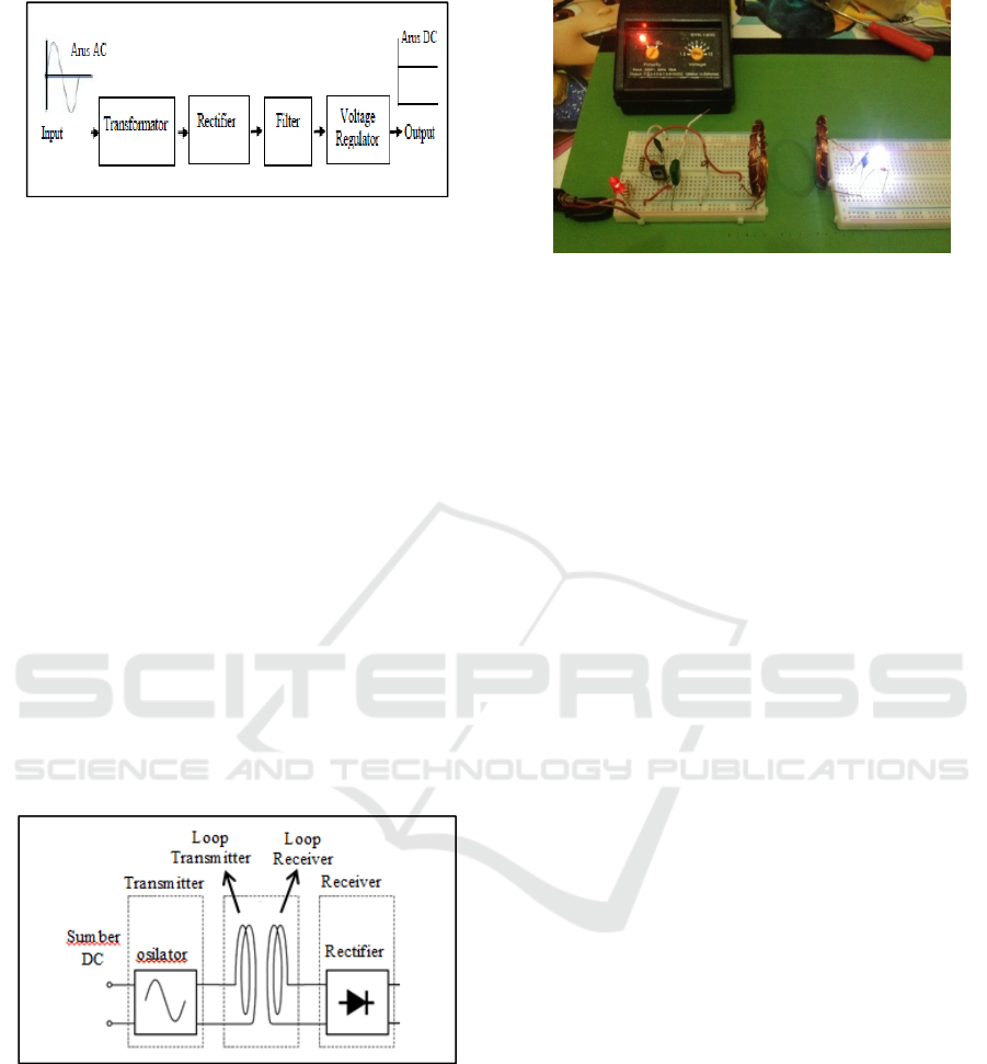
Figure 3: DC Power Supply Block Diagram (Adapter)
The transmitter circuit is a very important circuit
in the Wireless Power Transfer system because
without a transmitter circuit the electromagnetic
resonance process will not happen and the
transmission of electrical energy without cables is
not possible. The transmitter circuit works on the
principle of electromagnetic resonance generated by
an oscillator. The oscillator functions as a resonator
that generates electromagnetic waves of a certain
frequency and is induced inductively to the receiver
circuit. The oscillator used in this paper is Osley
Oscar.
The Receiver circuit consists only of the inductor
in the form of a wire winding which is not much
different from the wire winding on the transmitter
which is then connected to the load. The Receiver
circuit acts as a magnetic resonance induction
capture from the transmitter circuit to receive
electrical power to be supplied to the load. The
diagram block of the Wireless Power Transfer
system comprising thetransmitter and receiver
circuit is shown in Figure 4.
Figure 4: Block Diagram of the System.
The wireless energy delivery system that has
been designed is shown in Figure 5.
Figure 5: Wireless Power Transfer Setup.
Testing of Wireless Power Transfer system is
done on two types of copper loops with different
diameter cross-section. The diameter of the first
copper wire is 0.3 mm and the diameter of the
second copper wire is 0.6 mm. For each type of
copper wire diameter tested, 3 kinds of testing are
done by varying the input voltage ranging from 8
volts, 12 volts, and 15 volts. As for each tested
voltage, the value also varied the distance between
the transmitter and receiver side until the LED
indicator lights up.
3 RESULTS AND DISCUSSION
The results data of all the tests that have been
performed are shown in Table 1. Of the three tests
performed, the magnitude of the voltage sent from
the sender side greatly affects the acceptable
voltage. The distance between the transmitter and
receiver side also greatly affects the acceptable
voltage level. The farther the distance between the
transmitter loop and the receiver loop shown in
Figure 4, the more acceptable power the receiver
side will be. The effects of electromagnetic fields
that can be captured by the side of the smaller
receivers make the acceptable power smaller.
Similarly, if the distance between the transmitter and
the receiver's side is closer, the electromagnetic field
generated by the transmitter side will be greater
captured by the receiver side.
Analysis and Design of Wireless Power Transfer
39
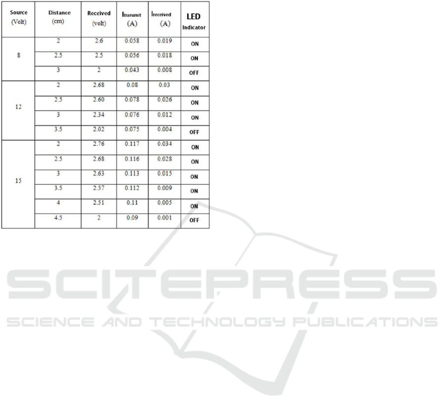
Table 1: Data Testing the cross-sectional area of the loop
of 0.6 mm.
From the test data in Table 1, when the 8-volt
source voltage with the distance between the sender
and receiver side 2 cm and 2.5 cms, the accepted
voltage by the receiver side is 2.6 volts,and 2.5 volts
and the LED indicator lit with currents of 0.019
amperes and 0.018 amperes. But when the distance
between the transmitter and the receiver side is 3 cm
the LED indicator turns off, with the voltage on the
receiver is 2 volts.
The maximum power that can be generated from
the transmitter circuit at the maximum voltage of the
adapter 15 volts at a distance of 2cm with a voltage
of 2.76 volts and maximum current 0.034 A. The
Power output, therefore, can reach up to 1.38 watt.
The affecting factor is the increasing distance of
transmission between the two coils so that the
electromagnetic induction will also be smaller.
Conversely, when the closer the voltage gets
bigger the better the radiated power so that the LED
indicator lights very bright.
4 CONCLUSION
Based on the results of the discussion the
conclusions are:
1. Transfer of electrical energy can be done
without using cable.
2. The farther the distance between the receiver
circuit and the transmitter circuit the smaller
the power that can be received by the receiver
circuit.
3. The change in energy value sent is proportional
to the input energy given, the greater the input
energy,the greater the energy delivered.
4. The maximum power that can be generated
from the transmitter circuit at the maximum
voltage of the adapter 15 volts at a distance of
2cm is 1.38 watts with a voltage of 2.76 volts.
REFERENCES
Andre Kurs,,AriesteidisKaralis, Robert Moffatt, J.D.
Joannopouos, Peter Fisher, & Marin Soljajic, 2007,
Wireless Power Transfer Via Strongly Coupled
Magnetic Resonances, in Science Express, VOL.317.
HelmyKautsar,
2010,AnalisadanRancangBangunRangkaian
Transmitter pada Transfer DayaListrikTanpaKabel, in
FakultasTeknikUniversitas Indonesia.
J.William F Stevenson, 1984, Power System Analysis,
inMcGraw-Hill, New York.
Kiwon Hwang, Seonghwan Kim, Seongkyu Kim,Yangban
Chun&SeoungyoungAhn, 2012, Design Of Wireless
Power Transfer System for Railway Application
inIJR-International Journal of Railway, Korea.
M.AhsanJavaid, Kamran LiaqatBhatti, ZeeshanRaza,
UmerIlyas& Shan UlHaq, 2015, Wireless Power
Transmission A Potential Idea for Future, inIJSER.
StanimirValcthec, Elena Boikova, Luis Jorge, 2012,
Electromagnetic Field As The Wireless Transporter of
Energy, inuninovaportugal, unl, Campus Caparica,
Portugal
ICMR 2018 - International Conference on Multidisciplinary Research
40
