
Experimental Study on Floating Breakwater Anchored by Piles
Yessi Kurniadi and Nira Yunita Permata
Civil Engineering Department, Institut Teknologi Nasional, Bandung, Indonesia
Keywords: Floating Breakwater, Piles.
Abstract: Floating breakwaters are applied in order to minimize material cost but still can reduce wave height. In this
paper we investigated floating breakwater anchored by piles based on experimental study in the laboratory
with model scale 1 : 13. Two types of floating model were tested with several combination wave height,
wave period and surface water elevation to determined transmission coefficient. This experimental study
proved that floating breakwater with piles can prevent wave height up to 27 cm. The physical model shows
that ratio of depth to wave length is less than 0.6 and ratio of model width to wave length is less than 0.3. It
is confirmed that if those ratio less than those value the transmission coefficient is higher than 0.5. The
result also shown that the first type model of floating breakwater can reduce wave height to 60.4 % while
the second one can reduce up to 55.56 %.
1 INTRODUCTION
Ports, dockyard, housing and other coastal facilities
are important to support human activities especially
in Indonesia whereas 70% are ocean. Coastline is
vulnerable to coastal erosion due to strong waves
action, therefore coastal protection structure is an
important infrastructure to developed utmost against
several conditions. Most of breakwater types that
has been built in Indonesia is Rubblemound
Breakwater type. This type can reduces wave up to
90% (Madsen and White, 1976) with transmission
coefficient 0.1 and appropriate for all coastlines, but
this structures has several disadvantages such as:
they are large structure, difficult to build, deep
foundations, and has expensive material cost.
Therefore, a floating breakwater was investigated to
overcome these problems. Research on floating
breakwater has been developed in many countries
before this century. At 1930 a floating breakwater is
placed in Aomori port in Japan to test its capability
to withstand waves (Cheng, et.al, 2013). In China
several floating breakwater types has been designed
and studied, a variety of flexible and rigid floating
breakwater has been carried out and analysed for its
stabilization structure and also its mooring
configuration. In Indonesia, several floating
breakwater research also carried out by Coastal
Research Centre from Indonesian Ministry of Public
Work and Housing. The floating breakwater
consisted of several module with separations and
most of mooring configurations are installed with
steel cable to foundations, however when this design
was built there was a problem with its stability
(Gumilang and Kurniadi, 2016). In this research we
proposed a floating breakwater anchored by piles to
stabilize the structure. Floating body is flexible to
water level but the mooring configurations are rigid
with pile. The purpose of floating breakwater is to
reduce wave height of wave transmitted (Ht) passed
the breakwater. Wave transmission coefficient (Kt)
is defined by following equation with Hi is incident
wave. Transmission coefficient should be small
enough as it represents the effectiveness of
breakwater.
2 EXPERIMENT STUDY
Floating breakwater experiment was conducted at
Ocean Engineering Laboratory, Institute Technology
Bandung (ITB). The wave flume is 40 m long, 1.5 m
high and 1.2 m wide. Bed was flat with smooth
concrete material. Revetment with 1:10 slope and
made from rubber was located at the end of the wave
flume use to absorb wave reflection. The wave
flume is provided with a piston type wave maker,
this wave maker can generate monochromatic waves
for shallow water with waves height ranging from
0.05 cm up to 0.33 cm. This wave flume system also
184
Kurniadi, Y. and Permata, N.
Experimental Study on Floating Breakwater Anchored by Piles.
DOI: 10.5220/0008656901840188
In Proceedings of the 6th International Seminar on Ocean and Coastal Engineering, Environmental and Natural Disaster Management (ISOCEEN 2018), pages 184-188
ISBN: 978-989-758-455-8
Copyright
c
2020 by SCITEPRESS – Science and Technology Publications, Lda. All rights reserved
provided with peilschaal, wave probe and a
computer to connect with wave probe (Fig.1).
Figure 1: Wave flume system and model configuration.
2.1 Model Scale
The principle of the use of scale model consists of
the possibility to reproduce the real problem (the
'prototype') on a smaller scale in such a way that the
phenomena in the scale model are similar in model
and prototype. This similarity regards various
aspects : (i) geometric similarity (ii) kinematic
similarity (iii) dynamic similarity. A geometric
similarity are based on Froude Number which can be
derived by stating that the model and prototype the
ratio between inertia and gravity force has to be the
same. The scale of a parameter is defined by the
ratio between the prototype value and the model
value of this parameter. The parameter for defining
scale in this research is water depth and maximum
wave height based on data at South Java coastal
area. Depth at prototype is 900 cm while depth at
wave flume is 70 cm. Therefore the geometric scale
model defined in Eq (1) where nL is scale, Lp is
prototype length and Lm is model length.
𝑛𝐿
12,86 13 (1)
While the scale is 1:13, dimensions for floating
breakwater models are shown at Table 1.
Table 1: Dimension for Prototype and Model.
Dimension Prototype (m) Model (cm)
Length 10,4 80
Diameter 0,65 5
Width 14,3 110
Height 11,5
88,46 89
Dimension Prototype (m) Model (cm)
Water Depth 9 70
Significant Wave
Height
1 7,7
2 15,4
2,5 19,2
2.2 Floating Breakwater Configuration
Model
2.2.1 Floating Breakwater Model 1
Floating Breakwater Model 1 consist of two rows of
floating pontoons made from fiberglass. Each of
these fiberglass pontoons was 46.5 cm long, 31 cm
wide, 22 cm high with the A shape as shown in Fig.
2. Pile dimension was 42 cm high from foundation
model. While foundation model was 93 cm long,
110 cm width, and 30 cm.
Figure 2: Floating Breakwater Model 1.
2.2.2 Floating Breakwater Model 2
Floating breakwater Model 2 shape was a
modification from Model 1, but this model has a
sawtooth design to prevent the wave (Fig.3).
Experimental Study on Floating Breakwater Anchored by Piles
185
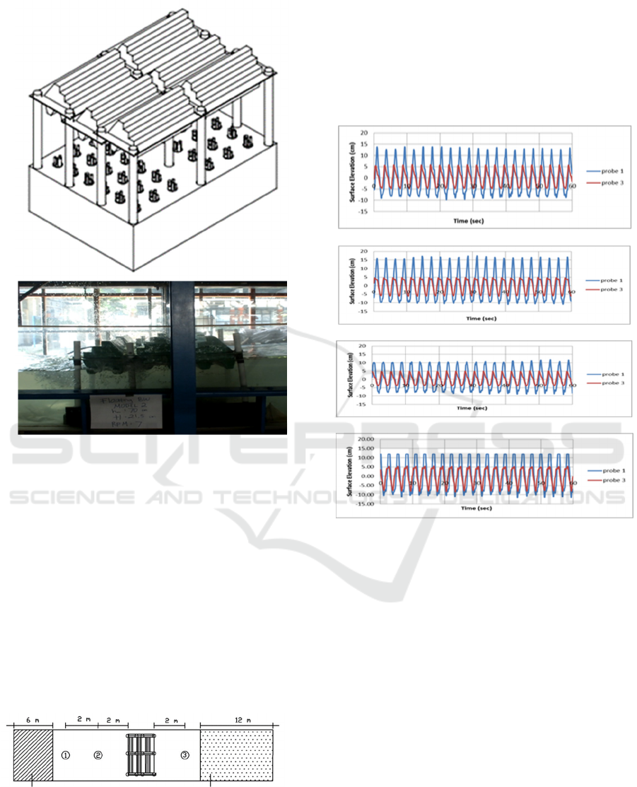
Figure 3: Floating Breakwater Model 2.
2.3 Laboratory Experiments
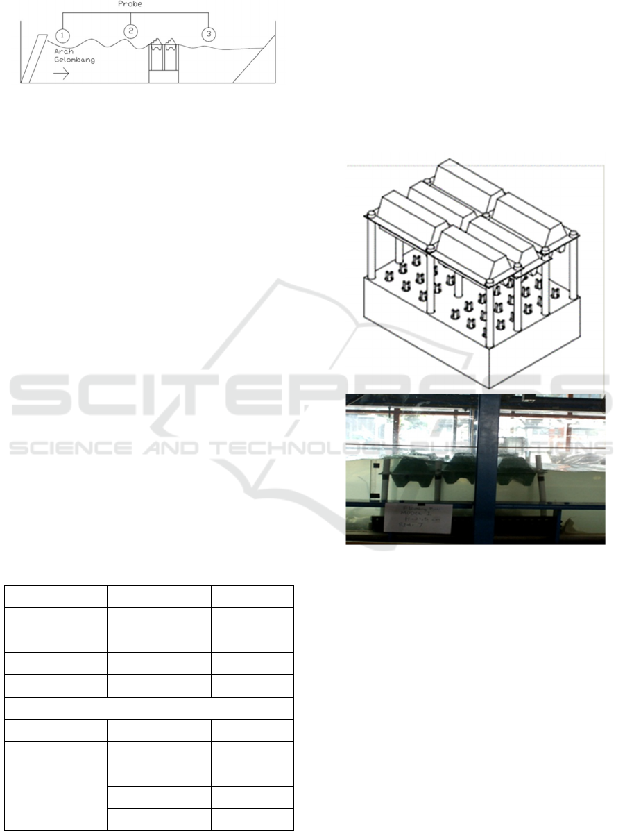
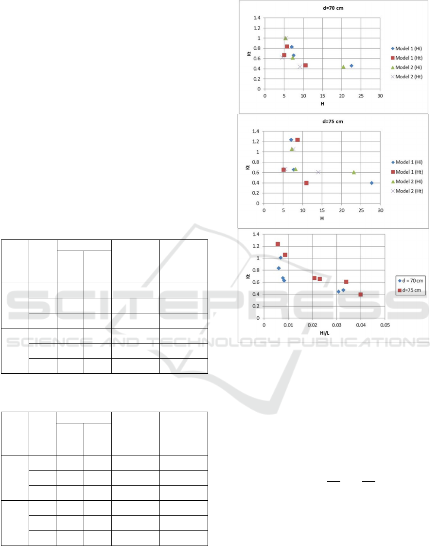
Three wave probes were installed 2 meter before and
2 meter after floating breakwater to measured wave
height (Fig.4). Wave probe in this laboratory was
measuring surface water elevation for each second
therefore a zero up crossing analysis is needed.
Wave probe number 1 is used as measurement for
incident wave height while wave probe number 3 is
for transmitted wave height. The design conditions
of floating breakwater include several significant
wave heights varies from 5 cm to 27 cm. Still water
level design varies from 70 to 75 cm based on
floating breakwater elevation.
Figure 4: Wave Probe Positions and Model Configuration.
Surface water elevation from design variations
were studied over two model floating breakwaters.
Figure 5 shows the surface elevation from Wave
Probe 1 and Wave Probe 3, this surface water
elevation data are analysed for wave incident and
transmitted wave. It can be shows that surface water
elevation at Wave Probe 3 behind floating structure
has reduced. At incident wave height above 20 cm
with different water level it shows that this structure
can reduce wave height significantly.
(a)
(b)
(c)
(d)
Figure 5: Surface Water Elevation at Probe 1 (blue line)
and Probe 3 (Red Line). (a)Surface water elevation at
Model 1 with water depth 70 cm and incident wave height
22.53 cm (b)Surface water elevation at Model 1 with
water depth 75 cm and incident wave height 27.79 cm
(c)Surface water elevation at Model 2 with water depth 70
cm and incident wave height 20.34 cm (d)Surface water
elevation at Model 2 with water depth 75 cm and incident
wave height 23.13 cm
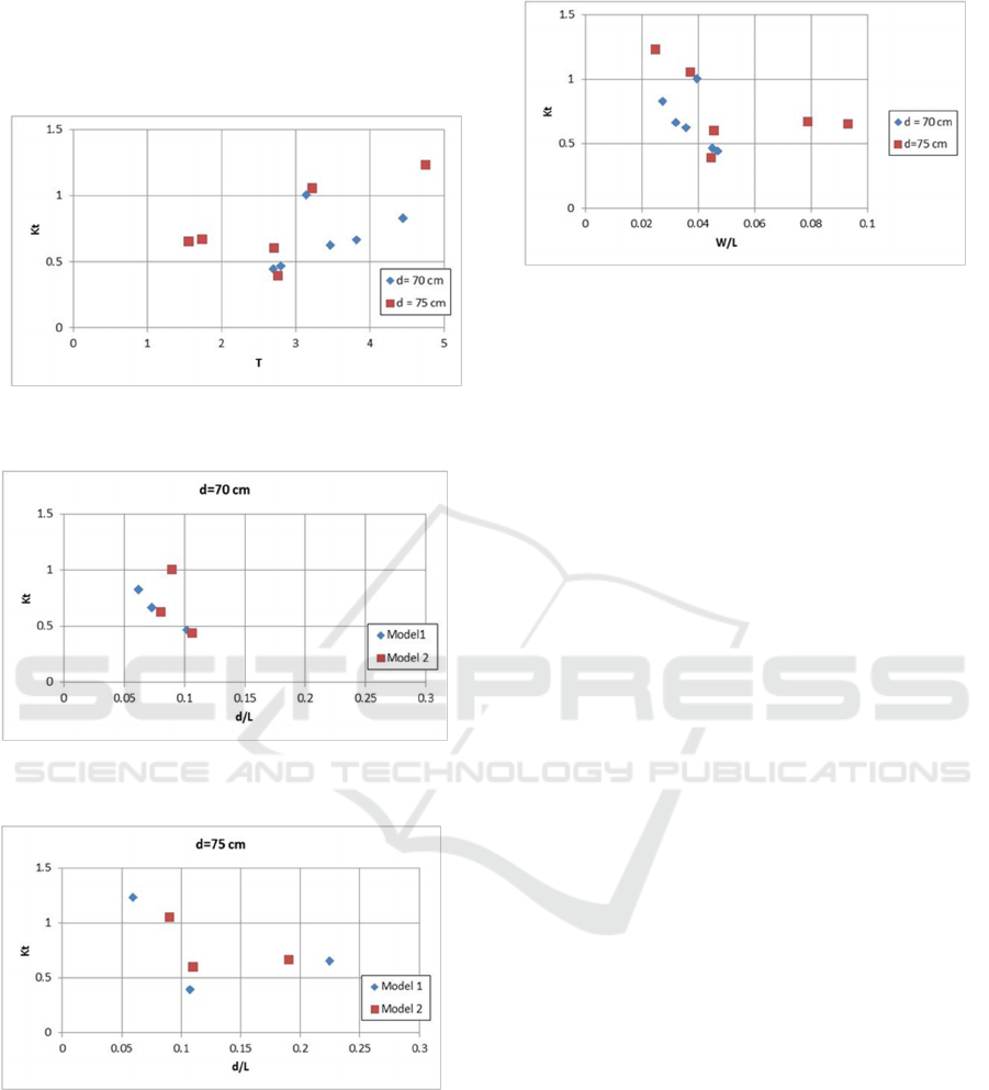
3 RESULT AND ANALYSIS
Transmission coefficient and wave height reduction
percentage were studied at several variation (Table
3). First variation with Model 1 at water depth 70
cm, at incident wave 6.908 cm yields the transmitted
wave height 5.746 cm with the transmission
coefficient 0.832 the wave height reduction is only
16.8%. While at the incident wave 22.532 cm the
wave height reduction is 53.17%. The condition of
ISOCEEN 2018 - 6th International Seminar on Ocean and Coastal Engineering, Environmental and Natural Disaster Management
186
model 1 at water depth 75 cm, the wave height
reduction is up to 60.471%. Another condition with
Model 2, the reduction percentage is lower than
previous model. The sawtooth design could not
reduce wave height significantly, this design yield
higher reflected wave and the transmission
coefficient higher than 1. The relationship between
transmission coefficient and wave height shows at
Figure 6. The bigger incident wave indicates the
smaller transmission coefficient. It can be conclude
that this floating breakwater structure effective at
high wave condition. As floating breakwater body
has 22 cm high, incident wave height less than 10
cm could not pass the structure therefore wave
height reduction percentage below 20 % and
reflected wave occurs. Non dimensionless parameter
relation between Kt and Hi/L also indicated that this
floating structure effective at high wave condition.
Table 2: Transmission Coefficient and Wave Height
Reduction Percentage at Water Depth 70 cm.
Float
ing
Break
water
Water
Depth
(cm)
H
1/3
(cm)
Transmisision
Coefficient
(Kt)
Wave Height
Reduction
Percentage
(%)
Hi Ht
Model
1
70 6.908 5.746 0.832 16.816
70 7.421 4.949 0.667 33.308
70 22.532 10.550 0.468 53.178
Model
2
70 5.333 5.371 1.007 -0.722
70 7.194 4.515 0.628 37.238
70 20.348 9.041 0.444 55.566
Table 3: Transmission Coefficient and Wave Height
Reduction Percentage at Water Depth 75 cm.
Float
ing
Break
water
Water
Depth
(cm)
H
1/3
(cm)
Transmission
Coefficient
(Kt)
Wave Height
Reduction
Percentage
(%)
Hi Ht
Model
1
75 7.000 8.646 1.235 -23.511
75 7.665 5.025 0.655 34.449
75 27.779 10.981 0.395 60.471
Model
2
75 7.209 7.617 1.057 -5.673
75 8.164 5.476 0.671 32.922
75 23.152 14.009 0.605 39.49
Figure 6: Relation between Transmission Coefficient,
Wave Height and ratio Hi/L.
3.1 Wave Transmission Coefficient
with d/L
Effect of water depth and wave lenght should be
analysed in a non dimension relationship between
wave transmission coefficient (Kt), relative depth
(d), and wave period (T). Wave length (L) for
shallow water is in Eq (2)
𝐿
tanh
(2)
From Figure 7 shows T and Kt with various
water depth. As wave period increases, the
transmission coefficient also increases. An effective
floating breakwater should have lower transmission
coefficient, therefore it can be seen that this
breakwater should placed in the lower wave period.
Figure 8 and 9 shows non dimensionless between
parameter Kt vs d/L at various condition. It can be
seen that when d/L less than 0.3 and the
transmission coefficient is higher than 0.5.
Relationship between relative structure width (W)
Experimental Study on Floating Breakwater Anchored by Piles
187
with transmission coefficient also studied here. From
previous research by Cheng et al it is conclude that
the smaller coefficient get the bigger W/L. Figure 10
shows similar result.
Figure 7: Relation between Transmission Coefficient (Kt)
and Wave Period (T).
Figure 8: Relation between Transmission Coefficient (Kt)
and d/L at water depth 70 cm.
Figure 9: Relation between Transmission Coefficient (Kt)
and d/L at water depth 75 cm.
Figure 10: Relation between Transmission Coefficient
(Kt) and W/L.
4 CONCLUSION
Wave transmission over floating breakwater
anchored by piles have been investigated and
analysed experimentally. This floating structure can
reduce wave height at high condition up to 23 cm on
scale 1:13 geometric scale.
From wave reduction percentage, Model 1 at
water depth 70 cm can reduce 16% until 53% while
at water depth 75 cm can reduce 34% until 60%.
Model 2 can at water depth 75 cm can reduce 37%
until 55% while at water depth 75 cm can reduce
32% until 39%.
REFERENCES
L.H. Cheng, C.Y.Fen, Y.H. Li, W.Y. Jiang, 2013.
Proceeding of the 7th International Conference on
Asia and Pacific Coasts.
O.S. Madsen, S. M. White, 1976. Reflection and
Transmission Characteristics of Porous Rubblemound
Breakwater. US Army Corps.
R. I. Gumilang, Y.N. Kurniadi, 2016. Jurnal Reka Racana
Teknik Sipil Itenas.
ISOCEEN 2018 - 6th International Seminar on Ocean and Coastal Engineering, Environmental and Natural Disaster Management
188
