
Stress Distribution along the Weld Toes of Tubular KT and KDT
Joints under Balance Axial Loads and In-Plane-Bending Moments
Rudi Walujo Prastianto, Yoyok Setyo Hadiwidodo, Sofyan Wahyu Widhestomo
and Rizky Yazhahir
Department of Ocean Engineering, Institut Teknologi Sepuluh Nopember, Kampus ITS Sukolilo Surabaya 60111, Indonesia
Keywords: Stress Distribution, Tubular KT, Tubular KDT.
Abstract: Jacket offshore structures are constructed from tubular members that consist of several types of multi-planar
tubular joints. So far, very few investigations have been performed on stress characteristics of such joints
due to their complexity. The present research is focused on the study of stress distribution along the weld
toe of brace-chord intersection for most critical brace due to the joint loading. In this paper tubular-KT and
KDT joints as elements of an offshore jacket platform are modelled as finite element models. The effect of
multi-planarity caused by adding a brace to the stress distribution along the weld toes is investigated under
two different loading conditions. To ensure validity of the model, Stress Concentration Factor (SCF) of the
KT-joints model was validated by Efthymiou SCF equations. An additional brace has been added within the
validated KT-joints models to form a multi-planar KDT joint, and the stress distribution along the weld toes
of the joints are investigated under balance axial load and in-plane bending moments. The results showed
that under balance axial loading, maximum stress occurred at a point of Crown 1 on the KDT-joints were
smaller than maximum stress occurred in the KT-joints as well as the case of in-plane bending moment
loading.
1 INTRODUCTION
Jacket offshore platforms that frequently used for oil
and gas exploitation in shallow water areas, during
their operation life will hold wave forces which
introduce variable loading on the structure. This
variable loading causes fatigue damage to the
structure members which usually initial crack will
appears at weld toes region of the tubular joints
where maximum stress occurs. Therefore, in the
fatigue design it is important to determine the stress
distribution along the weld toe of tubular joints.
In this paper, finite element analysis of tubular
KT and multi-planar KDT joints will be presented.
The results are stress distribution along the weld toe
of both type of the tubular joints. Multi-planarity
effect to the stress distribution along the weld toe of
the tubular KDT joint will be investigated. The
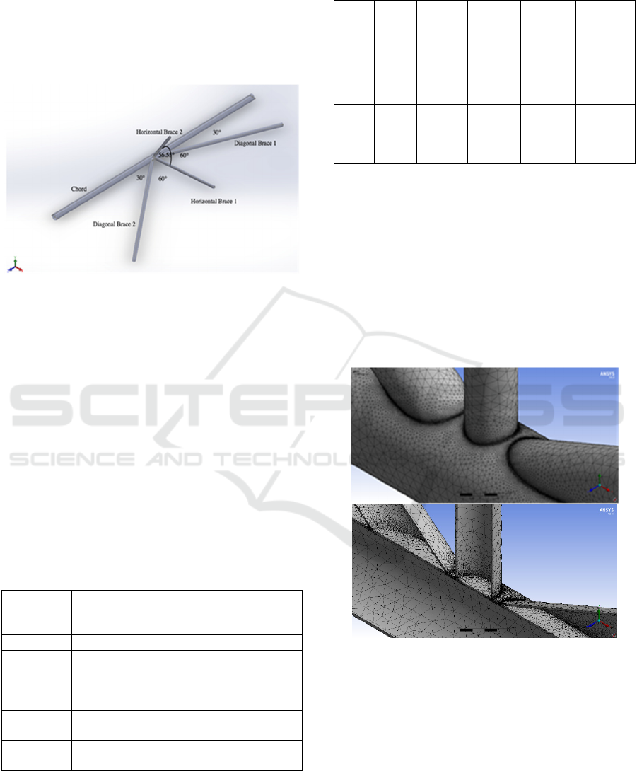
multi-planar tubular joint to be analyzed in the
present study is depicted in Fig. 1.
Numerous researches have been performed to
investigate the stress distribution for various multi-
planar tubular joints under several loading
conditions. Ahmadi and Zavvar (2016) numerically
studied the chord-side SCFs in two- and three-planar
tubular KT-joints under in-plane and out-of-plane
bending moments. Ahmadi and Nejad (2017)
proposed a new parametric formulas to calculate the
local joint flexibility of two-planar tubular DK-joints
subjected to four types of out-of-plane bending
(OPB) loads. Derivation the SCF formula for DT-
joints under axial loads was conducted by Jiang et
al. (2018). They used two types of error analysis to
verify the reliability of the formula. Using another
type of tubular joint which is XX-joints, Chiew et al.
(2000) investigated stress concentration factors
within the joints due to the axial, in-plane-bending
(IPB), and out-of-plane bending (OPB) loads. Based
on 64 finite element models they proposed general
SCF design equations for the joints. Recently
Prastianto et al. (2018) have conducted numerical
study on stress concentration factor distribution of
60 degrees two-planar DKT tubular joints subjected
to axial and in-plane bending loads.
Although several types of multi-planar tubular
joints as parts of offshore structures were already
been the subject of recent researches, but still no
170
Prastianto, R., Hadiwidodo, Y., Widhestomo, S. and Yazhahir, R.
Stress Distribution along the Weld Toes of Tubular KT and KDT Joints under Balance Axial Loads and In-Plane-Bending Moments.
DOI: 10.5220/0008650101700175
In Proceedings of the 6th International Seminar on Ocean and Coastal Engineering, Environmental and Natural Disaster Management (ISOCEEN 2018), pages 170-175
ISBN: 978-989-758-455-8
Copyright
c
2020 by SCITEPRESS – Science and Technology Publications, Lda. All rights reserved
research on the multi-planarity effect in the stress
distribution at the brace-to-chord intersection areas
of the tubular-KDT joint. Therefore, this research
will investigate the effect of additional one brace to
the KT tubular joint to form a tubular-KDT joint (as
shown at Fig. 1) on the stress distribution along the
weld toes of the joint.
Figure 1: Multiplanar tubular K double T (KDT) joint to
be analyzed.
2 FINITE ELEMENT
MODELLING
In this research, structure of tubular-KT and KDT
joints are modelled using a finite element method-
based software with the geometry as presented at
Fig. 1 for the KDT joint. Dimensions and material
properties of the models can be seen in Table 1 and
Table 2. Weld profile along the brace/chord
intersection of the model satisfies the AWS D1.1
(AWS, 2002).
Table 1: Geometry of the model of the tubular-KT and
KDT joints.
Thickness
(inc)
Outside
Diameter
(OD)
Intside
Diameter
(ID)
Length
(inc)
Chor
d
0.688 24 22.62 1032.68
Diagonal
Brace 1
0.5 14 13 487.19
Diagonal
Brace 2
0.5 14 13 611.55
Horizontal
Brace 1
0.364 10.75 16.5 278.22
Horizontal
Brace 2
0.364 10.75 16.5 149.80
Table 2: Material properties of the model of the tubular-
KT and KDT joints.
Spec
and
Grade
Yield
Strength
(ksi)
Modulus
Young
(ksi)
Shear
Modulus
(ksi)
Poisson’s
Ration
Chord
API
5L
Grade
290
290
29007.5
449
11603.01
75
0.3
Brace
API
5L
Grade
B
241
29007.5
449
11603.01
75
0.3
The finite element model of the tubular joints
using element type of solid three-dimensional with a
linear element tetrahedron for the model of braces,
chord, and weld profiles. The tubular joint models
are divided into two different zones according to the
computational requirements with sub-zone mesh
generation is used to ensure good quality meshing.
Meshing size is made smaller on the region around
brace-chord intersection rather than meshing size on
the areas that far from the brace-chord intersection.
The model with the meshing can be seen at Fig. 2.
Figure 2: Solid three-dimensional tetrahedron elements
used for the model.
According to Efthymiou (1988), fixity condition
of the chord ends in tubular joints of offshore
structures ranges from almost fixed to almost pinned
with generally being closer to almost fixed. For the
present study, the chord end fixity condition of the
joint models are also set to fixed support on both
ends of the chord. The braces of the structures will
be loaded with two different types of loading
conditions, namely balance axial loading and in-
Stress Distribution along the Weld Toes of Tubular KT and KDT Joints under Balance Axial Loads and In-Plane-Bending Moments
171
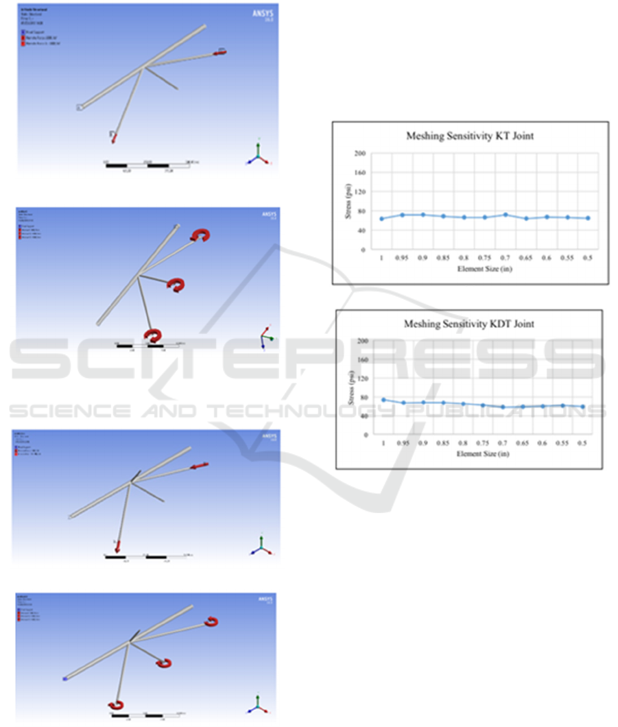
plane bending moment. The loading and boundary
condition applied to the models are illustrated at
Figs. 3 and 4 for the KT joint model and the KDT
joints models, respectively.
(a) Balance axial load
(b) In-plane bending load
Figure 3: Loads and boundary conditions for the KT-joint
models.
(a) Balance axial load
(b) In-plane bending load
Figure 4: Load and boundary conditions for the KDT-joint
models.
3 RESULTS AND ANALYSIS
3.1 Meshing Sensitivity Analysis
Meshing sensitivity analysis is performed to ensure
the consistency of the output from the finite element
analysis. This approach is done by changing element
size in the region around brace-chord intersection
line from 1.0 inch to 0.5 inch until stress at a
particular location reached a constant value as the
function of the size change.
(a)
(b)
Figure 5: Result of meshing sensitivity analysis due to
balance axial loading condition on: (a) KT-joint; (b) KDT-
joint.
From the results of the meshing sensitivity
analysis (see Figs. 5 and 6), for both cases of KT and
KDT joints it is found that stress output at particular
point nearly constant when element size reached
0.65 inch.
ISOCEEN 2018 - 6th International Seminar on Ocean and Coastal Engineering, Environmental and Natural Disaster Management
172
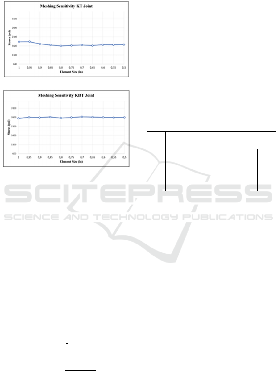
(a)
(b)
Figure 6: Result of meshing sensitivity analysis due to in-
plane-bending moment loading condition on: (a) KT-joint;
(b) KDT-joint.
3.2 Validation of Stress Concentration
Factor (SCF) for KT-joint
Stress Concentration Factor (SCF) is a ratio between
hot-spot stress in chord and nominal stress in brace.
In this research hot-spot stress calculation is
determined using two linear extrapolation points as
mentioned in DNVGL-RP-C203 (2001) by using the
maximum principal stresses occurred in the joint
model.
In this research, nominal stress occurred in brace
is obtained by reviewing stresses in 96 elements in
the middle of brace length to be analyzed which
located far enough from geometrical discontinuity
(weld toes area) and will be validated with following
equations.
For axial load condition:
𝜎
(1)
For in-plane-bending moment load condition:
𝜎
(2)
where,
σn : nominal stress for axial load or in-plane-
bending moment (MPa)
Mi : in-plane-bending moment (Nm)
d : brace diameter (m)
t : brace wall thickness (m)
F : axial load (N)
A : area (m2)
The obtained nominal stress and hot-spot stress
are used to calculate the stress concentration factor
of the joints. Prior to analyze stresses of the KDT
tubular joint, as a validation step the SCF from finite
element analysis for the KT joint will be compared
to Efthymiou SCF formula (Efthymiou, 1988) with
the results as presented in Table 3.
Table 3: Stress Concentration Factor Validation.
Model
FEM Efthymiou Error)%)
SCF
c
SCF
b
SCF
c
SCF
b
SCF
c
SCF
b
KT-
Joint
3.47 2.39 3.44 2.33 0.87 2.58
Both errors of the comparison for the chord and
brace stress concentration factor (SCFc and SCFb)
are under 5% which are 0.87 and 2.58, respectively.
Therefore, KT-joints model was good and can be
accepted, then a horizontal brace 2 can be added to
the KT-joint to become a KDT tubular joint for later
analysis.
3.3 Stress Distribution along Weld
Toes of the Tubular-KT and KDT
Joints
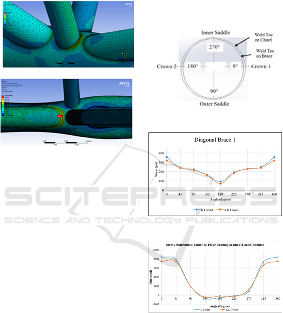
In this research, the stress in chord side is considered
to analyse stress distribution along the weld toes of
the joint model. The maximum principal stress was
used and the weld toes to be investigated are on joint
between the brace with the chord which have the
biggest stress among the other braces (see Fig. 7).
As shown at Fig. 7, maximum stress due to in-plane-
bending moment and balance axial loading occurs at
Horizontal Brace 1 and at Diagonal Brace 1,
respectively.
Stress Distribution along the Weld Toes of Tubular KT and KDT Joints under Balance Axial Loads and In-Plane-Bending Moments
173
(a)
(b)
Figure 7: Location of the maximum stress occurs due to:
(a) in-plane-bending moment; (b) balanced axial load.
Description of stresses along the weld toes of the
brace-chord intersection line is based on the
nomenclature depicted at Fig. 8. There are four main
points namely Crown 1, Outer Saddle, Crown 2, and
Inner Saddle where are located at 0o, 90o, 180o, and
270°, respectively. Stress distribution along the weld
toes of the tubular-KT and KDT joint models are
presented at Figs. 9 and 10 for two loading
conditions which are balanced axial load and in-
plane-bending moment, respectively.
Fig. 9 depicts a comparison of stress distribution
along brace-to-chord intersection line between the
tubular-KT and KDT joints occurred at diagonal
brace 1 due to balance axial loading. Among all
points observed, the stress significantly decreased at
two points namely Crown 1 and Crown 2 for the
KDT joint.
Meanwhile, Fig.10 shows a stress comparison for
the two different tubular joints occurred at horizontal
brace 1 under in-plane bending moment loading. For
this mode of loading, the stress significantly
decreased at Crown 1 and two other points at
positions of 45O and 315O, respectively. Patterns of
the stress distribution are very much different to that
for axial loading case.
Generally after the uniplanar KT joint is added
by one horizontal brace to the center of the chord to
become a multi-planar tubular-KDT joint, stress
along brace-to-chord intersection line mostly
becomes smaller in all points reviewed (0o to 360o),
especially at a point of Crown 1. This results occur
for both two cases of loading conditions applied,
balance axial load and in-plane bending moment.
Figure 8: Nomenclature of the observed points along the
brace-to-chord intersection line.
Figure 9: Stress distribution along the weld toes of the
joint under balance axial load.
Figure 10: Stress distribution along the weld toes of the
joint under in-plane-bending moment.
4 CONCLUSIONS
From the present study, the following conclusions
can be drawn:
• The maximum stress along the weld toe of the
KT and KDT tubular joints under balance axial load
ISOCEEN 2018 - 6th International Seminar on Ocean and Coastal Engineering, Environmental and Natural Disaster Management
174

occurs in a member of Diagonal Brace 1 at the
Crown 1 point (0o).
• For in-plane-bending moment case, the
maximum stress along the weld toe of the KT and
KDT tubular joints can be found also at the Crown 1
point (0o), but in critical member of Horizontal
Brace 1.
• The multi-planarity caused the KDT-joint has
smaller maximum principal stress than the KT-joint
under both loading cases of balance axial load and
in-plane bending moment. This is due to partly, the
occurred stress redistributed onto the additional
plane where the new brace laid. In turn, this
condition will also make the value of SCF of the
KDT-joint smaller than the SCF of the KT-joint.
ACKNOWLEDGEMENTS
The authors would like to thank the Institute for
Research and Community Services (LPPM), Institut
Teknologi Sepuluh Nopember (ITS) Surabaya for
supporting this research by a grant of “Laboratory
Research 2018”.
REFERENCES
American Welding Society (AWS), 2002. Structural
welding code: AWS D 1.1, USA.
DNVGL RP-C203, 2001. Recommended Practice, Fatigue
Strength Analysis of Offshore Steel Structure.
H. Ahmadi, A.Z. Nejad, 2017. Geometrical effects on the
local joints flexibility of two-planar tubular DK-joints
in jacket substructure of offshore wind turbines under
OPB loading, Thin-Walled Strctures, 114, 122-133.
H. Ahmadi, E. Zavvar, 2016. The effect of multi-planarity
on the SCFs in offshore tubular KT-joints subjected to
in-plane and out-of-palne bending loads, Thin-Walled
Strctures, 106, 148-165.
M. Efthymiou, 1988. Development of SCF formulae and
generalized influence functions for use in fatigue
analysis, OTJ 88, Surrey, UK.
R.W. Prastianto, Y.S. Hadiwidodo, I.F. Fuadi, 2018.
Stress concentration factor of a two-planar double KT
tubular joint due to in-plane bending loading in steel
offshore structures, MATEC Web Conference, 177,
01006, EDP Sciences.
R.W. Prastianto, Y.S. Hadiwidodo, I.F. Fuadi, M.B.Y.P.
Naibaho, P.N. Rahardianto, 2018. Stress concentration
factor distribution of inclined brace in multiplanar
offshore tubular double KT joints. IOP Conf. Ser.:
Earth Environ. Sci., 162 01204.
S.P. Chiew, C.K. Soh, N.W. Wu, 2000. General SCF
design equations for steel multiplanar tubular XX-
joints, International Journal of Fatigue, 22, 283-293.
Y. Jiang, K. Yuan, H. Cui, 2018. Prediction of stress
concentration factor distribution for multi-planar
tubular DT-joints under axial loads, Marine
Structures, 61, 434-451.
Stress Distribution along the Weld Toes of Tubular KT and KDT Joints under Balance Axial Loads and In-Plane-Bending Moments
175
