
Strength Analysis of Glass Fibre Reinforced Plastics B-series
Propeller for Traditional Purse Seine Boat in the North Coastal
Region of Central Java Indonesia
Aulia Windyandari
1
, Gunawan Dwi Haryadi
2
, Ahmad Fauzan Zakki
3
and Insanu Abdilla Cendekia Abar
3
1
Industrial Technology Department, School of Vocation, Diponegoro University, Indonesia
2
Mechanical Engineering Department, Faculty of Engineering, Diponegoro University, Indonesia
3
Naval Architecture Department, Faculty of Engineering, Diponegoro University, Indonesia
Keywords: Finite Element Method, Standard B-series Propeller, Computational Fluid Dynamic, Plastic Glass Reinforced
Materials.
Abstract: In the previous study, the standard B-series propeller was developed to improve the propulsion performance
of the traditional purse seine boat in the North Coastal Region of Central Java. Since the developed propeller
design was adopted glass reinforced plastics material, therefore it is important to evaluate the strength
performance due to its application as a propulsion system. The aim of the research is to investigate the
structure response of the developed standard propeller that would be applied to the fishing boats typically
found in the North Coastal Region of Central. Finite element method (FEM) and computational fluid dynamic
analysis (CFD) for assessing the stress distribution and the maximum deformation of the standard was
performed. The loading condition of the propeller model is determined by using the pressure which is exerted
on the propeller that is provided by CFD analysis. The stress distribution and the maximum deformation
responses will be discussed.
1 INTRODUCTION
Recently, the standard B-series propellers designs
have been developed to improve the propulsion
performance of traditional purse seine boat in the
North Coast Region of Central Java (Windyandari,
2018). As a part of the research work, this paper is
focused on the investigation of structure responses of
the developed B-series propeller that using glass fiber
reinforced plastic as the material. In order to obtain a
reliable result, the process of assessing the structure
response of the propellers involves a complex
numerical analysis. Numerical analysis and
simulation is an iterative procedure that able to solve
complex problems with reliable and accepted
accuracy for predicting and estimating the exact
behaviour. As the propeller geometry is complex and
its loading conditions are more complicated, therefore
the structural response analysis should performed
with the complex computational method. Hence for
the pressure load, the computational fluid dynamics
analysis is conducted to obtain the pressure
distribution on the propellers. The complex
geometries structure analysis can be carried out by
adopting the finite element method, where the
propeller blade can be modelled as a beam, shell and
solid elements.
2 LITERATURE REVIEW
The propeller design involved complex geometry.
Some of studies are obtained to solve the complex
geometry in the structure analysis. Taylor et. al
introduced a technique that was known as elementary
beam theory which is treated the propeller blade as a
cantilever to the propeller hub (Taylor, 1993). Cohen
was proposed a simplified propeller blade model
using a helicoidally shell with infinite width (Cohen,
1955). However the approach method is not suitable
for a shell with finite width. In other studies, it is also
observed that the analytical methods based on
conventional mechanics do not offer a significant
improvement result for estimating and predicting the
Windyandari, A., Haryadi, G., Zakki, A. and Abar, I.
Strength Analysis of Glass Fibre Reinforced Plastics B-series Propeller for Traditional Purse Seine Boat in the North Coastal Region of Central Java Indonesia.
DOI: 10.5220/0008565401490152
In Proceedings of the 6th International Seminar on Ocean and Coastal Engineering, Environmental and Natural Disaster Management (ISOCEEN 2018), pages 149-152
ISBN: 978-989-758-455-8
Copyright
c
2020 by SCITEPRESS – Science and Technology Publications, Lda. All rights reserved
149

stress of the propeller blade, instead of it is involved
for merely routine design activities (Connolly, 1961;
Atkinson, 1968; Wereldsma, 1965; McCarthy, 1969;
Boswell, 1969).
Since the analytical method have some limitation,
therefore numerical and computational technique
such as finite element method (FEM) and
computational fluid dynamic (CFD) analysis is
adopted to conduct the propeller performance
analysis. Some of research work is reviewed to shows
the role of finite element method in marine structure.
Sontvedt (1974) have studied the prediction of quasi
static and dynamic stress of marine propeller blade.
Young adopted a coupled boundary element method
(BEM) and finite element method to study the hydro-
elastic behaviour of the flexible composite propeller
in wake flow (Young, 2007). In the other study,
Young presented the structure response of flexible
composite propellers using fluid-structure interaction
analysis (Young, 2008). Blasques (2010) tailored the
laminate for controlling the blade deformation and the
developed thrust. Hong (2017) studied the
performance and efficiency of the 438x series of
composite propellers using finite element method and
computational fluid dynamics method (CFD). The
application FEM also can be found in the vibration
and buckling analysis of the marine structure (Yudo,
et.al. 2017; Windyandari, et.al. 2018).
Table 1: The traditional purse seine boat characteristics.
Boat design parameters Dimension
Length of Perpendicular (Lpp) 13.1 m
Breadth 4.15 m
Draft 1.56 m
Height 1.97 m
Block Coefficient 0.53
Service speed 9 knot
Total Resistance 15.18 kN
Wake Fraction 0.15
Number of propeller Single Screw
Height of propeller aperture 1.20 m
Thrust deduction 0.12
Table 2: Propeller data specification.
Design
Parameters
3-Bladed 4-Bladed 5-Bladed 6-Bladed
Propeller
Diam. (D)
0.90 m 0.90 m 0.90 m 0.90 m
Area Ratio
(AE/A0)
0.35 0.56 0.62 0.74
Pitch Ratio
(P/D)
1.0 1.0 1.0 1.0
Advanced
Coeff. (J)
1.281 1.340 1.353 1.347
3 MATERIALS AND METHODS
In this research work the developed B-series propeller
for traditional purse seine boat are studied with the
boat characteristics and the propeller specifications
data as can be seen in the Table 1 and Table 2,
respectively. The objective of this study is to
investigate the structure response of the developed B-
series propeller of the traditional pursed seine boat in
the North Coastal Region in Central Java.
3.1 Material of the GFRP Propeller
The glass fibre reinforced plastic (GFRP) materials
have been implemented in many products in the field
of marine engineering such as boat, turbine, outfitting
components and propellers. GFRP material has
offered high strength characteristics with the low
weight and better corrosion resistance.
In the numerical analysis of the investigation of the
structural response, the material of propeller was
defined as an isotropic material. Although the
composite material is should be represented as an
orthotropic, however, for the simplification of the
computational process, the isotropic is still reliable to
provide an accurate result for estimation of the
propeller structure behaviour. The mechanical
properties of the GFRP for propeller material is can
be found in Table 3.
Table 3: Mechanical properties of GFRP for the propeller
material.
Properties GFRP
Young Modulus, (E) 42.70 GPa
Poisson Ratio (ν) 0.30
Shear Modulus (G) 5.10 GPa
Density (ρ) 1800.00 kg/m
3
3.2 Finite Element Model and
Simulation
The finite element model was defined as
representation of the B-series propeller. In order to
define the pressure load on the propeller blade, the
flow simulation should be made using CFD analysis.
The CFD model was considered as a cylindrical
domain. The inlet and outlet was defined as an
upstream and downstream, respectively. The
unstructured grid was adopted for the model
computation. The propeller model is represented by
the solid element which is located on the centre of the
origin axis in the coordinate system. The CFD model
is can be seen on the Fig.1.
ISOCEEN 2018 - 6th International Seminar on Ocean and Coastal Engineering, Environmental and Natural Disaster Management
150
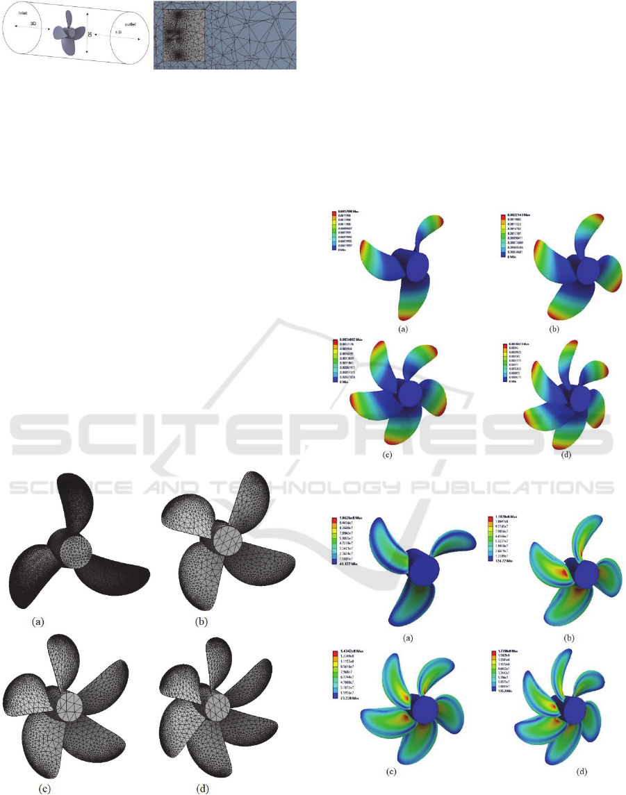
Figure 1: CFD simulation model: Size of domain (left),
Unstructured grid mesh model (right).
Since the pressure distribution is obtained as the
result of the CFD analysis, the propeller blade FE
model is defined with the pressure results. The
pressure load is defined on the face of blade surface
and the back of blade surface. The detail of CFD
analysis to determine the pressure load can be found
in the previous study, (A. Windyandari, G. D.
Haryadi, and A. F. Zakki, 2018). The FE model of the
B-series propellers can be seen in the Fig. 2. The
meshing process was made using the auto mesh tools
of the software application. The entire solid elements
was modelled using 3D element which is 4 nodded
tetrahedrons mesh is adopted. The FE models of the
propellers consist of 198093 nodes, 1323641
elements for 3-bladed propeller; 1615082 nodes,
96463 elements for 4-bladed propeller; 198124
nodes, 118424 elements for 5-bladed propeller and
228001 nodes, 135632 elements for 6-bladed
propeller. The boundary condition of the simulation
was defined as fix support on the centre of the
propeller hub.
Figure 2: FE model of propellers: (a) 3-bladed;
(b) 4-bladed; (c) 5-bladed; (d) 6 bladed.
4 RESULTS AND DISCUSSIONS
The strength characteristics of the B-series propeller
for traditional purse seine in the North Coastal Region
of Central Java have been simulated. The numerical
simulation using FEM was conducted to observe the
essential parameters for the integrity of propeller
strength such as maximum deformation and stress
distribution which is represented as Von Mises Stress.
The results of the simulation are presented in Fig. 3
and Fig.4 for maximum deformation and Von Mises
stress distribution, respectively.
Figure 3: Maximum deformation of propellers:
(a) 3-bladed; (b) 4-bladed; (c) 5-bladed; (d) 6 bladed.
Figure 4: Stress distribution of propellers: (a) 3-bladed;
(b) 4-bladed; (c) 5-bladed; (d) 6 bladed.
The deformations of each propeller are 1.80 mm,
2.21mm, 2.50mm and 3.84 mm for 3-bladed
Strength Analysis of Glass Fibre Reinforced Plastics B-series Propeller for Traditional Purse Seine Boat in the North Coastal Region of
Central Java Indonesia
151

propeller, 4-bladed propeller, 5-bladed propeller and
6-bladed propeller, respectively, see Fig. 3.
According to the deformation results, it might be seen
that the maximum deformation is occurred on the 6-
blade propeller with the magnitude of deformation of
3.84 mm, see Fig. 3(d). The results can be explained
that the 6-bladed propeller which is able to produce
the largest thrust force have generated the largest
pressure load on the blade structure. Therefore the
generated pressure might influence the deformation
response of the propeller. The simulation results also
show that the larger blade numbers generally produce
a larger structure deformation response. The tendency
can be explained since the larger blade number was
produced the larger thrust force. This can be
identified that the larger generated thrust might
increase the hydrodynamic pressure on the blade
propeller.
The maximum stress of the propellers is obtained
on the connection between the blade and the hub of
the propeller, see Fig. 4. The stress distributions of
each propeller are 106 MPa, 120 MPa, 143 MPa and
174 MPa for 3 bladed propeller, 4-bladed propeller,
5-bladed propeller and 6-bladed propeller,
respectively. The stress distribution results have
shown the same tendency with the deformation
results that the larger blade number generates the
larger maximum stress on the propeller structure.
Therefore, it is also can be indicated that the
generated thrust of the propeller have an influenced
on the stress response of the blade propeller. Since the
properties of the GFRP material has the tensile
strength of 870 MPa, all of the propellers design is
reliable to support the propulsion system for the
traditional boat.
5 CONCLUSIONS
The study on the structural response of Glass Fibre
Reinforced Plastic B-series propellers for traditional
purse seine in the North Coastal Region of Central
Java was made. For determining the pressure load of
the propeller, the simulation of flow on the propeller
is conducted using CFD analysis. Subsequently the
pressure distribution results are defined as the load
condition on strength analysis using finite element
method.
According to FE analysis results, the maximum
deformation of 3.84 mm is obtained on the 6-bladed
propeller and the minimum deformation of 1.80 mm
is observed on the 3-bladed. It may be concluded that
the deformation of the propeller has enlarged while
the number of blade is increased. It can be explained
that the increase of propeller blade number could
generate the larger thrust force that may influence the
pressure on the blade. In the case of stress
distribution, the maximum stress of 174 MPa is
occurred on the 6-bladed propeller. The maximum
stress of the 6-bladed propeller is 64.15% larger than
3-bladed propeller. Although the 6-bladed propeller
have the largest maximum stress, however the entire
propeller design is accepted and reliable to be
implemented for the propulsion system of traditional
purse seine boat because the maximum stress is below
the tensile strength of GFRP material.
REFERENCES
A. Windyandari, G. D. Haryadi, A. F. Zakki, 2018.
Excellent Fundamental Research Report. unpublished.
A. Windyandari, H. Yudo, A. F. Zakki, 2018. ARPN
Journal of Eng. Appl. Scie. 13, 6.
D. W. Taylor, 1933. The speed and power of ships, Eansdell
Inc, Washington D. C.
H. Yudo, A. Windyandari, A. F. Zakki, 2017. IJCIET 8, 8.
J. E. Connolly, 1961. Trans. RINA 103.
J. H. McCarthy, 1969. NSIIDEC Report 3182.
J. P. Blasques, 2010. Mar. Struc. 23.
J.W. Cohen, 1955. Netherlands Res. Cen. T. N. O. Report
21S.
P. Atkinson, 1968. Trans. RINA 110.
R. J. Boswell, 1969. NSRDC Report 3247.
R. Wereldsma, 1965. Netherlands Res. Cen. T. N. O. Report
51M.
T. Sontvedt, 1974. Comp. & Struc. 4, (1974).
Y. Hong, 2017. Ocean Eng. 144.
Y. L. Young, 2007. Proc. 16th Conf. on Composite Mat.
Y. L. Young, J., 2008. Fluids & Struc. 24.
ISOCEEN 2018 - 6th International Seminar on Ocean and Coastal Engineering, Environmental and Natural Disaster Management
152
