
Investigation of Structural Response Due to Impact Load on the
Small Water Plane Area Twin Hull Autonomous Surface Vehicles
(SWATH-ASV)
Ahmad Fauzan Zakki
1
, Aris Triwiyatno
2
and Bandi Sasmito
3
1
Naval Architecture Department, Engineering Faculty, Diponegoro University, Indonesia
2
Electrical Engineering Department, Engineering Faculty, Diponegoro University, Indonesia
3
Geodetical Engineering Department, Engineering Faculty, Diponegoro University, Indonesia
Keywords: Structural Response, Impact Load, SWATH-ASV.
Abstract: The main objective of the research was to investigate the structural response of The Small Water Plane Area
Twin Hull Autonomous Surface Vehicles (SWATH-ASV) due to the impact load. The impact load was
defined as the drop phenomena that might be occurred while SWATH-ASV is being carried and transported.
The behavior of the absorbed energy in several drop scenarios also was studied. Numerical simulation was
performed using nonlinear finite element method to obtain the numerical simulation data. The size of the
damage of the SWATH-ASV was estimated as a design consideration for the structure strength. The external
dynamics parameters which include as the contact point location and drop velocity is being considered on the
simulation analysis. The internal energy and deformation size which is caused by the drop phenomena will
be discussed.
1 INTRODUCTION
Rapid development in the growth of numerical
simulation technology, capability of computational
speed and relatively large memory capacity makes
designers able to create and evaluate of new product
designs performance in a virtual world.
Through the finite element method, complex
simulations able to provide any valuable information
for the design and development of reliable new
products like those that have already existed and even
better as an improvement on the existing product
capabilities. The manufacturer confirmed that this
method is very useful, as this method has facilitated
them enormously in achieving a better productivity at
lower unit costs. This method is also capable for
supporting manufacturers to develop engineering
components that are easily produced and to create any
products that are efficient in terms of material
expenditure.
In 2018, an autonomous surface vehicle (ASV)
has been developed by Zakki et. al. (2018) which is
adopted the Small Water plane Area Twin Hull
(SWATH) technology for the hull form. The ASV
was developed to support bathymetry survey
activities in coastal area. In the development of the
SWATH-ASV, the designers attempt to obtain a
product that has reliable quality for its hull
components. For achieving these quality standards,
the SWATH-ASV products must meet the
requirements of being able to withstand loads that can
result in high stress structures (Ali, et.al, 2011).
Therefore this study is focused on the investigation of
structural responses that were subjected for impact
loading, especially in the drop phenomena. The
structure load is the impact load that is occurred when
the SWATH-ASV product is dropped from a certain
height. Therefore it can be predicted that the
developed ASV product has reliable structural
integrity when it drops from the certain height during
the survey activities.
2 DROP TEST AND FINITE
ELEMENT ANALYSIS
2.1 Drop Test
Durability assessment that is important to be
conducted for the development of new products is a
144
Zakki, A., Triwiyatno, A. and Sasmito, B.
Investigation of Structural Response Due to Impact Load on the Small Water Plane Area Twin Hull Autonomous Surface Vehicles (SWATH-ASV).
DOI: 10.5220/0008565001440148
In Proceedings of the 6th International Seminar on Ocean and Coastal Engineering, Environmental and Natural Disaster Management (ISOCEEN 2018), pages 144-148
ISBN: 978-989-758-455-8
Copyright
c
2020 by SCITEPRESS – Science and Technology Publications, Lda. All rights reserved
drop test. Drop tests are carried out in the full load
conditions and it is dropped from a certain height on
a solid floor such as a steel floor or concrete floor.
Drop test experiments are costly and require
relatively extensive experimental setting times.
However with the computational simulation using
finite element analysis (FEA), the drop test can be
performed without conducting a physical product
prototype which is required moulding process and
experimental studies. FEA is able to estimate the
performance of the response of product structure that
is loaded nearly realistic conditions (Abunawas,
2010).
2.2 Finite Element Analysis
Finite Element Analysis is numerical procedure that
is accurate and flexible to estimate the performance
of a structure, mechanism or process in a loading
condition while being operated. FEA is generally
associated with the design validation process before
the manufacturing process is carried out. Furthermore
FEA is also widely used in the initial stages of the
design process to try / evaluate new concepts before
physical prototypes are made and tested. Some
advantages of FEA include:
1. Supporting innovation, as FEA supports designers
to think creatively with the accepted risk level.
2. Supporting the process to achieve an optimum
design rather than acceptable design, resulting in
better performance and lower material costs, as
FEA is able to support numerical evaluation
processes through evaluation study with multiple
scenarios.
3. Understanding and controlling operations in the
parametric study of product design, as FEA
provides information about detailed performance
that cannot be obtained through experimental test.
4. Reducing development research costs and
working time, by replacing experimental test into
numerical studies, as FEA models are usually
faster than creating the physical prototypes and
setting up the experimental equipment.
In the last four decades, finite element method
becomes a well-known numerical method, since
computer applications are widely implemented on the
manufacture industries. Versatility and flexibility
have been offered by FEA and it is applicable for
solving the complex boundary problems. FEA
commonly used for the structure analysis in the static
and dynamic characteristics. Instead of structure
analysis, FEA might be applied for solving the heat
conduction, fluid mechanics, electromagnetic and the
other continuity problems (Zakki and Windyandari,
2016; Windyandari and Zakki,, 2018; Windyandari,
et.al, 2018; Yudo, et.al, 2017; Prabowo, et.al, 2018).
There are many commercial finite element analysis
software that already support the manufacture
industries such as: ANSYS, MSC
NASTRAN/PATRAN, SOLIDWORK, LS-DYNA,
HYPERWORKS, and many others.
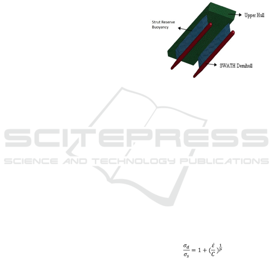
Figure 1: Finite Element Model of SWATH-ASV.
3 DROP TEST SIMULATION
MODELLING
The finite element analysis model of the SWATH-
ASV is described in the Fig. 1. The meshing process
of the SWATH-ASV model is carried out using LS-
PREPOST (LSTC, 2009). All of the plate/shell of the
SWATH-ASV structures was modelled using 2D
elements which is 4 nodded bilinear Belytchko-Tsay
shell element is adopted. The finite element model of
SWATH-ASV consists of 11706 numbers of nodes
and 11674 numbers of shell elements.
In the case of material modelling, Cowper-
Symonds strain rate material model is adopted to
capture the material behaviour, since the impact
problem such as drop test is a high strain rate loading
condition. The equation of Cowper-Symonds is
defined as follow:
(1)
Where is dynamic yield stress, is static stress, is
strain rate, C is material constant which is defined as
100, P is material constant which is defined as 10. The
mechanical properties of the FE model can be seen on
the Table 1.
Investigation of Structural Response Due to Impact Load on the Small Water Plane Area Twin Hull Autonomous Surface Vehicles
(SWATH-ASV)
145
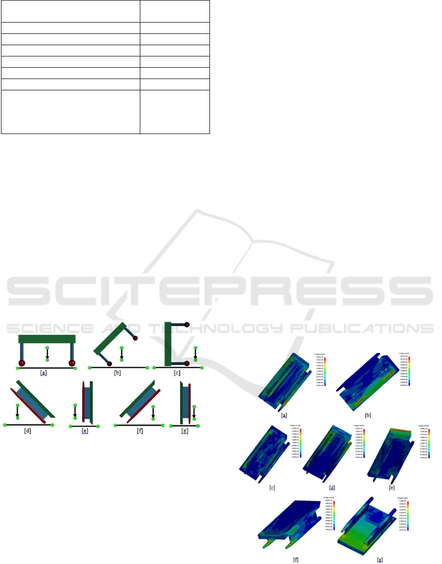
Table 1: FE Model mechanical properties.
Properties Item Material of FE
Model
Density (kg/mm
3
) 1.522 ×10
-06
Poisson Ratio 0.30
Longitudinal Young Modulus (GPa) 67.28
Transverse Young Modulus (GPa) 14.25
Longitudinal Tensile Strength (GPa) 1.05
Transverse Tensile Strength (GPa) 0.43
Strain Rate Model Cowper-
Symmonds
C= 100 and
P=10
The boundary condition of the simulation has
been defined as the drop orientations which are
considered for the numerical analysis. The drop
orientations are consist of even keel, 45 degrees heel,
90 degrees heel, 45 degrees trim by stern, 90 degrees
trim by stern, 45 degrees trim by bow and 90 degrees
trim by bow, see Fig. 2. The floor material is
considered as an infinite planer rigid material. For the
numerical simulation, the SWATH-ASV is given an
initial velocity of 6.26 m/s that is equivalent with the
2m drop velocity before striking the rigid floor. The
type of contact algorithm used is node to surface
contact with the contact thickness of 0.0001 m for the
analysis. Non friction contact is adopted for the
SWATH-ASV and the rigid floor.
Figure 2: Drop test orientation: [a] even keel; [b] heel 45º;
[c] heel 90º; [d] trim by bow 45º; [e] trim by bow 90º; [f]
trim by stern 45º; [g] trim by stern 90º.
4 RESULT AND DISCUSSIONS
The drop phenomena for seven different orientations
of SWATH-ASV have been simulated. The integrity
of the SWATH-ASV structure was analysed to study
the various essential parameters such as Von Misses
Stress and crash energy absorbed by the SWATH-
ASV components.
4.1 Maximum Effective Stress
In the event keel drop condition, the maximum Von-
Mises stress obtained on the bottom part of demihull
and the connection between strut and upper hull, see
Fig 3a. It can be explained that the bottom part of the
demihull is exerted the impact force and distributed
the load to the ASV structure. Since the maximum
Von-Mises of 201 MPa is below the tensile strength,
therefore the ASV is not expected to be failed during
the event keel drop.
The maximum Von–Misses stress on the
connection between strut and upper hull also can be
found on the other drop conditions such as heel 45º,
heel 90º, trim by bow 45º and trim by stern 45º, see
Fig. 3. It is indicated that the connection of strut and
upper hull is a vulnerable area that might be failure if
the ASV has experiencing the higher drop height. The
tendency can be explained since the connection
design have a sharp geometry that could be identified
as a stress concentrator. Therefore the rounded joint
design should be considered to reduce the maximum
stress that might be occurred.
According to the result of numerical simulation, it
is shown that the maximum Von-Misses stress
obtained on the heel 45 degrees condition is 241 MPa.
Failure of the connection of strut and the upper hull
can lead the leakage of the hull structure. However
the Von Misses stress of the connection area is below
the tensile strength of 1.05 GPa. Therefore the
connection of strut and upper hull is expected not
failed under 2 m drop.
Figure 3: The Maximum Von-Misses stress: [a] even keel;
[b] heel 45º; [c] heel 90º; [d] trim by bow 45º; [e] trim by
bow 90º; [f] trim by stern 45º; [g] trim by stern 90º.
ISOCEEN 2018 - 6th International Seminar on Ocean and Coastal Engineering, Environmental and Natural Disaster Management
146
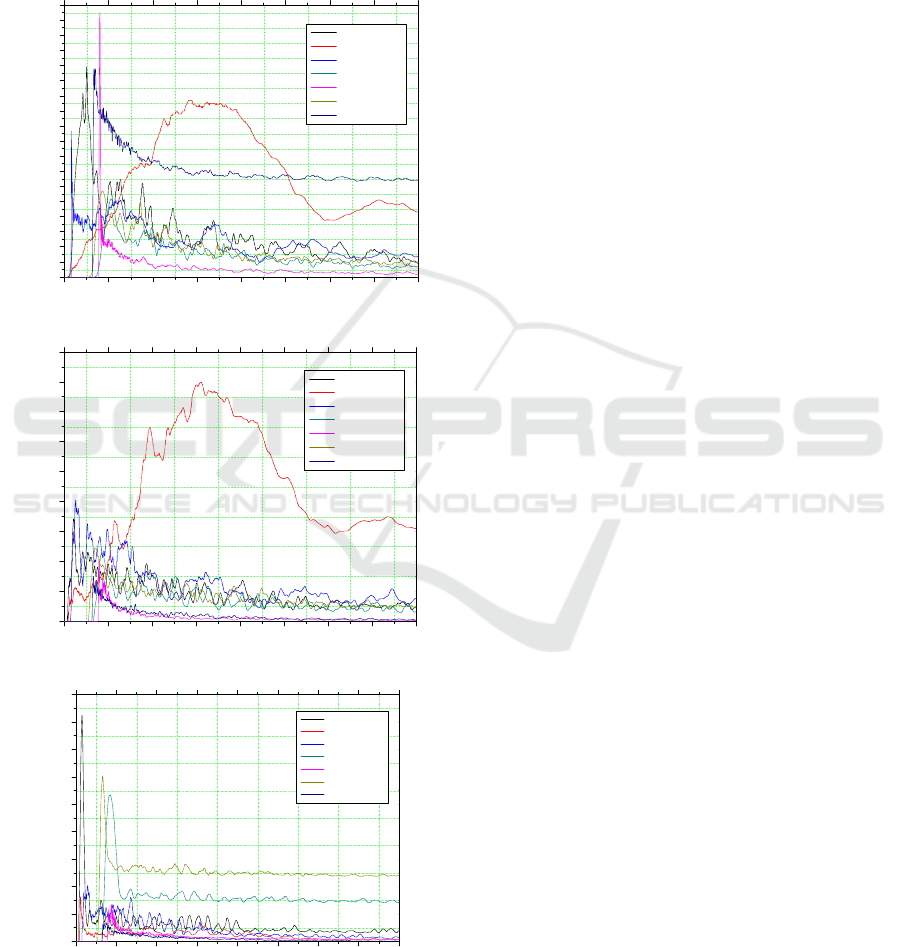
4.2 Absorbed Rupture Energy
The rupture energy absorbed by all of the components
of SWATH-ASV structure after 2m drop is shown in
the Fig. 4. It can be seen that the maximum energy
which is absorbed by the upper hull is observed in the
trim by stern 90º. It might be explained that the upper
hull is experiencing the impact energy while the ASV
0 1020304050607080
0
10
20
30
40
50
60
70
80
90
100
110
120
130
140
150
160
170
180
Rupture Energy [kNmm]
Time [ms]
Even Keel
Heel 45 Deg
Heel 90 deg
Stern 45 deg
Stern 90 deg
Bow 45 deg
Bow 90 deg
(a)
0 1020304050607080
0
10
20
30
40
50
60
70
80
90
Rupture Energy [kNmm]
Time [ms]
Even Keel
Heel 45 Deg
Heel 90 deg
Stern 45 deg
Stern 90 deg
Bow 45 deg
Bow 90 deg
(b)
0 1020304050607080
0
10
20
30
40
50
60
70
80
90
Rupture Energy [kNmm]
Time [ms]
Even Keel
Heel 45 Deg
Heel 90 deg
Stern 45 deg
Stern 90 deg
Bow 45 deg
Bow 90 deg
(c)
Figure 4: The rupture energy absorbed: [a] by upper hull;
[b] by strut; [c] by demihull.
was striking the rigid floor. Although the upper hull
absorbed most of the impact energy, however the
maximum stress is occurred on the stern peak
structure because the stern peak have a narrow shape
hull form as the stress concentrator.
On the strut part of the structure, the maximum
rupture energy is occurred on the heel 45º condition.
It can be explained that during the collision period the
strut was experiencing the collision energy and the
maximum effective stress have shown in the
connection between strut and upper hull as the
structure response. Otherwise the design geometry of
the connection between strut and upper hull have a
sharp shaped that would concentrate the stress in the
area. Therefore the connection area is the
vulnerableregion that should be improved by
providing the smooth connection such as rounded
joint and hull haunch.
Finally, the demihull part was shown a maximum
absorbed energy on the even keel drop condition. The
rupture energy was absorbed when the demihull strike
the rigid floor and then the energy was distributed to
the upper hull through the strut structure. Therefore
the upper hull part has shown larger absorbed rupture
energy, especially in the connection between strut and
upper hull. According to the numerical simulation
result, it can be concluded that the connection
between strut and upper hull is critical region that
should be modified to improve the drop performance
of the SWATH-ASV.
5 CONCLUSIONS
The investigation of SWATH-ASV structural
response was made due to the impact load on the 2m
drop phenomena. It was obtained that the maximum
effective stress (Von –Misses stress) was occurred on
the Heel 45º condition. The maximum effective stress
of 241 MPa is smaller than the tensile strength of the
SWATH-ASV material. Therefore it could be
concluded that the SWATH-ASV structure is able to
withstand the impact load during the 2m drop test.
In the case of absorbed rupture energy that might
influence the strength integrity of the SWATH-ASV
structure, the maximum absorbed rupture energy is
occurred on the trim by stern 90º, it is indicated that
the upper hull have absorbed most of the impact
energy. Although the maximum rupture energy was
shown by the trim by stern 90º, However the most
critical region of the SWATH-ASV structure is the
connection between strut and upper hull, since the
area have a sharp shaped that might become as stress
concentrator. Therefore it can be concluded that the
Investigation of Structural Response Due to Impact Load on the Small Water Plane Area Twin Hull Autonomous Surface Vehicles
(SWATH-ASV)
147

connection between strut and upper hull is vulnerable
region that should be modified to provide smooth
connection for eliminating the stress concentration
that might be increased the effective stress.
REFERENCES
A. F. Zakki, A. Triwiyatno, B. Sasmito, M. H. Nubly, 2018.
MATEC Conf. 177.
A. F. Zakki, A. Windyandari, D. M. Bae, 2016. JMST-
Taiwan 24, 3.
A. R. Prabowo, D. M. Bae, J. M. Sohn, A. F. Zakki, B. Cao,
B., Q. Wang, 2018. AEJ 57, 3.
A. R. Prabowo, J. M. Sohn, D. M. Bae, A. F. Zakki, B. I.
Hasrianto, 2018. Curved and Layered Struct. 5, 1.
A. Windyandari, A. F. Zakki, 2018. MATEC Conf. 158.
A. Windyandari, H. Yudo, A. F. Zakki, 2018. ARPN JEAS
13, 6.
H. Yudo, A. Windyandari, A. F. Zakki, 2017. IJCIET 8, 8.
LSTC, LS-DYNA User’s Manual, 2009.
M. B. Ali, S. Abdullah, M. Z. Nuawi, and A. K. Ariffin,
2011. IOP Conf. MSE. 17.
M. Kh. Abunawas, 2010. Int. Jour. Comp. Sc. Net. Secur.
10, 5.
ISOCEEN 2018 - 6th International Seminar on Ocean and Coastal Engineering, Environmental and Natural Disaster Management
148
