
Influence of the Cut-out Shape on the Fatigue Ship Structural Detail
Septia Hardy Sujiatanti
1
, Totok Yulianto
1
, Wing Hendroprasetyo Akbar Putra
1
and Rizky Chandra
Ariesta
1
1
Department of Naval Architecture, Faculty of Marine Technology, Institut Teknologi Sepuluh Nopember, Surabaya,
Indonesia
Keywords: Cut-out Shape, Fatigue, Ship.
Abstract: Damage structured mostly occurred caused by the crash. One of the causes of the accident is the fatigue of
the hull side of the ship. The composition of the side hull structure comprises a detailed structure that often
experiences a wave pressure load failure. In this study, the load given is the dynamic load of the wave. The
structural pressures generate the stress used to evaluate the strength and determine the fatigue life of the
structure. This study involves modelling details structured with 3 variations of the model. The modelling is
conducted using Finite Elements Analysis software by calculating the pressure load that adjusts the location
of the model. The model of each cut-out is created variations. These variations resulted in the estimate fatigue
life. The fatigue life calculation used several approaches i.e. Simplified Fatigue Analysis and Fracture
Mechanics.
1 INTRODUCTION
Generally, the ship structure may be longitudinally
stiffened or transversely stiffened with stiffeners and
bulkheads. In its entire life is complex structure will
be accepted to distinguished load conditions
beginning with the ship launching and continuing
with each sailing and interval; docking for survey and
repair (Joem, 2010). Although a ship may be designed
to withstand the ultimate imposed by a wave, failure
can occur due to apparently low stresses generated by
the continuous load (Mathews, 2013).
Fatigue of structural components in ships is a long
known problem and has been investigated in depth
owing to its relevance in design. Fatigue design
became an important subject due to use of higher
strength materials, serve environmental conditions
and optimized structural dimensions (Hughes, 2010).
The factors with contributing to the fatigue of ship
structure are the local configuration and geometry of
details structured (DNV, 2010). In ship structure, a
major fraction of the total number of fatigue damages
occurs in panel stiffeners on the ship side and bottom
on the boundaries of ballast and cargo tanks. In
tankers, cracks occur mostly on the side longitudinals
at the connections to transverse webs (CSR, 2012).
The aim of this paper is to evaluate fatigue life
using three geometry shape of slot design. Analyze
from the model using finite element analysis. The
goal of the Finite Element model was to successfully
predict the stress value with various of geometry
shape. The best of geometry shape can be assumed
based on the age resulted from the calculation
process.
2 LITERATURE REVIEWS
In general, the design of a construction must be able
to withstand loads and other factors that cause failure
in the structure itself. At sufficient loads, secondary
construction in particular, on construction details can
be made simple and save production but still meet the
required strength requirements. Based on several
construction designs in this research, an evaluation of
the strength and age of the cut-out design was carried
out. cut out is a structure on a ship classified as a small
construction on a ship or commonly called structural
intersection. Cut out itself has an important role as a
constituent of construction.
Cut out is a part of the construction that serves to
blow reinforcement to another structure or support,
for example, which is located in a non-impermeable
bulkhead in addition to providing strength to the
construction ring which is circular in a transverse
position. Cut out is located on the web frame or side
Sujiatanti, S., Yulianto, T., Putra, W. and Ariesta, R.
Influence of the Cut-out Shape on the Fatigue Ship Structural Detail.
DOI: 10.5220/0008375601110115
In Proceedings of the 6th International Seminar on Ocean and Coastal Engineering, Environmental and Natural Disaster Management (ISOCEEN 2018), pages 111-115
ISBN: 978-989-758-455-8
Copyright
c
2020 by SCITEPRESS – Science and Technology Publications, Lda. All rights reserved
111
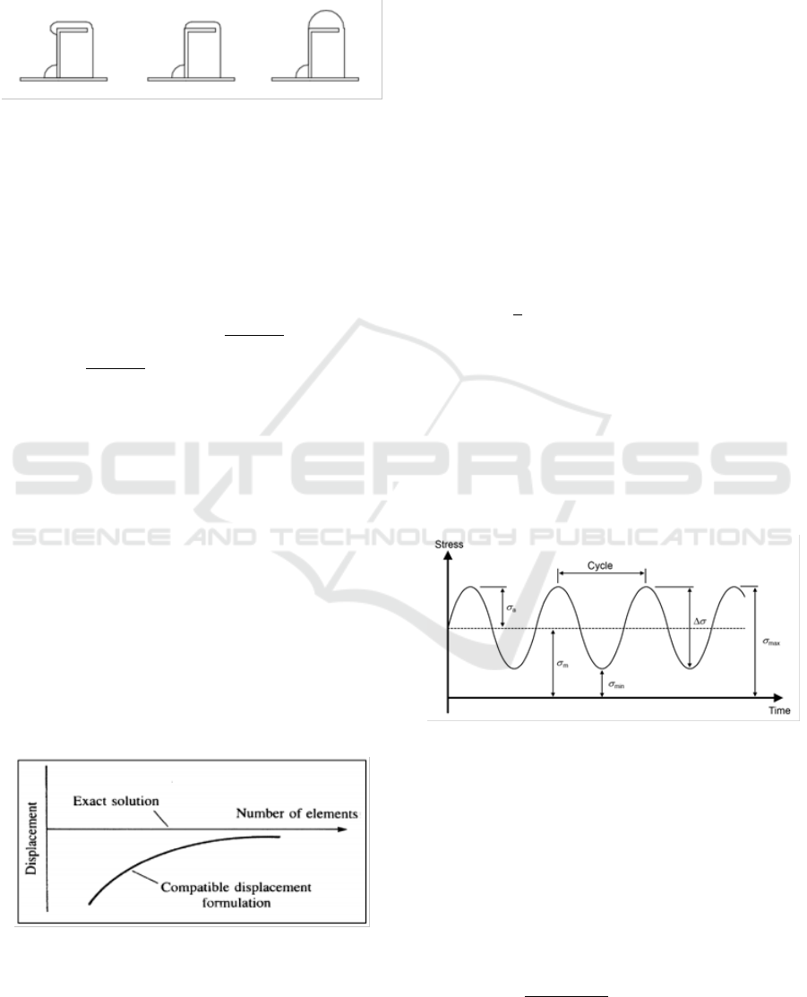
transverse. The cut-out design is adjusted to the shape
of the profile that penetrates into it. Cut out has
several types of shapes for L profiles as can be seen
in Figure 1.
Figure 1: Cut-out design shapes.
2.1 Loading
In this research, the quasi-static loading is used, this
type of load is a compressive load caused by waves
regardless of the roll angle. Then the formula used to
calculate is according to the equation as follows
(CSR, 2012):
(1)
The load applied to the model is added with a
dynamic pressure load in the tank to see the response
given from the cut-out. Calculations used are
appropriate with the rules.
2.2 Stress
The level of accuracy in the process of finite element
analysis is directly proportional to the increase in the
number of elements used. But the increasing number
of elements used also affects the amount of time
needed during the analysis process. In many cases,
this problem is solved by changing the element size
to obtain more detailed results in the area of the
structure. The relationship between the number of
elements can be seen in Figure 2.
Figure 2: Diagram number of elements and function
parameters.
Many variations between structure and load make
it difficult to determine the size of elements that can
provide results with the best accuracy. Determination
of element size is based on the experience carried out
in the analysis that has been done before.
Fatigue is a typical phenomenon in structures
(both structures on land and structures located in
waters), especially those made of steel material.
Fatigue is a combination of dynamic local stresses
(residual stress), defects, surface roughness, and other
parameters. In welded structures, the area on the weld
is the weakest condition, where crack growth begins.
Local stresses that cause fatigue include nominal
stress, stress hotspots, and notch stress. The nominal
stress is a conventional approach to fatigue analysis,
where the type of stress that occurs is included in a
beam theory for simple structures so that nominal
stress equations are formulated as follows:
(2)
Where,
σ = nominal stress (MPa)
F = Force (N)
A = Area (mm2)
Generally, the loading can be divided into two
parts, namely constant-amplitude loading and
variable amplitude loading. The constant-amplitude
loading can be seen in Figure 3.
Figure 3: Constant-amplitude loading.
The main parameter in fatigue calculation is the
stress range (Δσ), mean stress (σm) and stress ratio
(R). The stress range is formulated as follow
(3)
(4)
The mean stress and stress ration are formulated
as follow
(5)
ISOCEEN 2018 - 6th International Seminar on Ocean and Coastal Engineering, Environmental and Natural Disaster Management
112
(6)
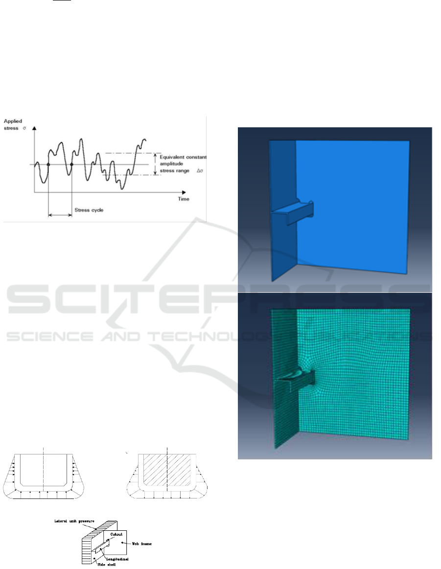
In the type of loading with variable amplitude
loading different from the load that occurs in the type
constant amplitude loading. Variable amplitude
loading has a very complex function, where the
probability of the order of magnitude of stress range
during the interval has very little time. The type of
loading with the variable amplitude loading can be
seen in Figure 4.
Figure 4: Variable-amplitude loading.
3 METHODOLOGY
Fatigue is a very complex analysis of ship structures
problem. It results from many factors along with the
following are most important is the interaction of
structural element geometry, material (mechanical
properties, it's structured), loading mode (its
magnitude, effect of condition, mean stress), and
stress directions. The models for the local detail just
discussed. With assumptions are shown in Figure 5,
the load contributions are reduced to deformation of
the web frame due to external sea water pressure,
internal pressure exerted by the vertical acceleration
of cargo oil, and sea pressure on the side shell
(Elhewy, et.al, 2016).
Figure 5: Loading condition.
The finite element analysis is carried out to
analyse the directions stress of details structured. The
variations of details structured were modelled using
finite element software. In this case, using three-
dimensional finite element models were developed.
twenty nodes solid element brick with six degrees of
freedom per node was used to all the models because
it is considered the most stable. The local structure
models were analysed for various structural details
geometry. The models and meshing process of details
structured are shown in Figure 6.
Figure 6: Structural finite element model.
By loading on the shell, load from sea pressure
and inner tank pressure will be transferred to the
variation of models from shell and web frame (Bai,
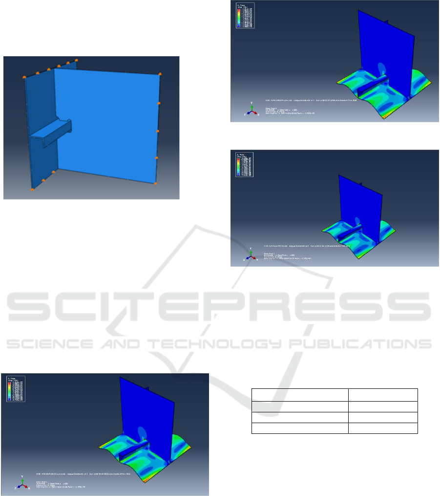
2003). The boundary conditions pin (displacement x,
y, z =0) and free rotations or following Figure 7.
Because, the structured of web frame and side shell
have the free edge in vertical and horizontal following
plate, i.e. the y-axis (web frame) and z-axis (side
shell). Defining boundary conditions is one of the
most important steps in finite element analysis. For
External
Internal
Influence of the Cut-out Shape on the Fatigue Ship Structural Detail
113
this condition or local analysis models, the boundary
conditions imposed by the surrounding structures
should be based on the deformation or forces
calculated from the global models (ABS, 2002).
Figure 7: Boundary condition.
4 RESULT AND DISCUSSION
In this paper, the fatigue life calculation can be
accomplished in two methods. First, the value of
maximum stress as shown in Figure 8 to Figure 10
determined to calculate fatigue simplified method.
The second step is the calculation of fatigue load
cycles from initial to the final crack. The calculation
is carried out to estimate the number of load cycles
that occur each year for a ship with a crack in details
structured.
Figure 8: Stress distribution on the 1st design cut-out.
Figure 9: Stress distribution on the 2nd design cut-out.
Figure 10: Stress distribution on the 3rd design cut-out.
According to the maximum stress on the design
cut-out the fatigue life of the structural details was
calculated with two methods. The fatigue life
calculation result using simplified method is on the
design cut-out are given in Table 1.
Table 1: Fatigue life calculation using the simplified
method.
Cut-out design
T (Year)
1
st
Model
77
2
nd
Model
65
3
rd
Model
36
5 CONCLUSIONS
According to the analysis results presented in Table 1
and Table 2, it can be concluded that the lifetime in
the 1st design is 77 years is the longest time.
Therefore, the variation of the cut-out design can be
recommended for details structured is the 1st design.
REFERENCES
ISOCEEN 2018 - 6th International Seminar on Ocean and Coastal Engineering, Environmental and Natural Disaster Management
114

A. M. Elhewy, Laheta, and Younes, "Analysis of Fatigue
Crack Growth inn Ship Structural Details," POLISH
MARITIME RESEARCH, vol. 23, pp. 71-82, 2016.
ABS, Rules for Building and Classing Steel Vessels,
American: American Bureau of Shipping, 2002.
CSR, Common Structural Rules for Double Hull Oil
Tankers, IACS, 2012.
D. N. Veritas, Fatigue Assesment of Ship Structures,
German: DNV, 2010.
E. Mathews and C. Nandakumar, "Fatigue Life Estimation
of Ship Structure," International Journal of Scientific
and Engineering Research, vol. IV, no. 5, pp. 217-219,
2013.
F. Joem, Ship Structural Analysis, and Design, New Jersey:
The Society of Naval Architecture and Marine
Engineer, 2010.
H. O. F and P. J. K, Ship Structural Analysis and Design,
English: The Society of Naval Architects and Marine
Engineers, 2010.
Y. Bai, Marine Structural Design, United Kingdom:
ELSEVIER, 2003.
Influence of the Cut-out Shape on the Fatigue Ship Structural Detail
115
