
Wave Energy Conversion with Floating Objects for the Coast of East
Java
Heri Saptono Warpindyasmoro and Hanny Hosiana Tumbelaka
Electrical Engineering Department, Petra Christian University, Jl. Siwalankerto 121 - 131 Surabaya, Indonesia
Keywords: Wave Energy Conversion, Cylindrical Absorber, Cone Absorber.
Abstract: The coast of East Java has ocean waves with varying significant wave heights and wave periods. To convert
wave energy into electrical energy, equipment is needed, which is a floating object. This floating object
serves to convert wave energy into mechanical energy which is then converted into electrical energy.
Energy conversion will be maximum if the ocean wave frequency same with natural frequency of floating
objects. The natural frequency of floating objects is determined by the shape of the floating object. This
study compares two floating objects, namely cylinder and cone shaped. From the results of simulations, the
cylinder shape is more suitable to be applied on the south coast of East Java, while the cone shape is more
suitable to be applied on the north coast of East Java.
1 INTRODUCTION
Energy produced by ocean waves is a very potential
energy in the world and the most efficient when
converted to electrical energy (Drew, et.al, 2009).
But the implementation as a real electricity generator
is still very minimum. Most are still on a laboratory
scale. The energy produced by ocean waves is
depended on the parameters of ocean waves, namely
the significant wave height and wave period. At each
location has a varying significant wave height and
wave periods (Faizal, et.al, 2014). Therefore we
need a wave energy conversion mechanism (Wave
Energy Converter, WEC) that is suitable for wave
conditions in each of these locations. Furthermore,
the mechanical energy is converted into electrical
energy. In general, WEC can be categorized as
oscillating water columns (OWC), overtopping
devices, attenuators and point absorbers (Aggidis
and Taylor, 2017). The OWC structure is a column
with two holes. The first hole faces the sea where a
wave comes. The wave then press the water that
pushes the air in the column. In the second hole, it
relates to an atmosphere where an air turbine is
placed to convert it into electrical energy (Ravinesh,
et.al, 2016). OWC is usually installed on the
shoreline. The advantage of this system is the ease
of installation. Whereas the weakness is the power
of the wave is not as big as offshore. The structure
of overtopping devices is a water reservoir that
higher position than sea level. If there is a wave,
water will collect in that place. Then the water flows
downward to move the turbine to convert it into
electrical energy (Frigaard, 2008). The WEC
attenuator is a long absorber that the incoming wave
will move it perpendicular to the direction of the
wave. So that each part of the attenuator moves
vertically (Lopez, et.al, 2013). Point absorber is a
floating object with a certain shape that is partially
or completely submerged at sea level. When a wave
comes, this floating object will move vertically
(heave). This floating object movement will drive
the generator with a certain mechanism to produce
electrical energy (Faizal, et.al, 2014).
Point absorber is one of the WECs that will be
developed in shape and size. By optimizing the
shape and size of floating objects, floating objects
will be suitable for that location, so the maximum
wave energy conversion will be obtained. When the
waves come, floating objects will move vertically
(heave). This floating object is called a point
absorber, because in this part the wave energy is
absorbed by the system. This movement will excite
the movement to produce mechanical energy to be
converted into electrical energy, called Power Take
Off (PTO). PTO will be very efficient if the
movement is limited to one dimension only (Pecher,
2017). To maximize energy, a condition is needed
where the natural frequency of floating objects must
Warpindyasmoro, H. and Tumbelaka, H.
Wave Energy Conversion with Floating Objects for the Coast of East Java.
DOI: 10.5220/0008375100870090
In Proceedings of the 6th International Seminar on Ocean and Coastal Engineering, Environmental and Natural Disaster Management (ISOCEEN 2018), pages 87-90
ISBN: 978-989-758-455-8
Copyright
c
2020 by SCITEPRESS – Science and Technology Publications, Lda. All rights reserved
87
be equal to the frequency of ocean waves. Whereas
the natural frequency of floating objects depends on
the shape of the floating object. Therefore, to
optimize the energy conversion, the structure and
shape of the floating object becomes very important.
2 WAVE ENERGY ON THE
COAST OF EAST JAVA
Sea wave characteristics on the southern coast of
East Java (the Indonesian Ocean) and the northern
coast of North Java (Java Sea) have several
differences. The difference in characteristics
between the two locations is related to the
significant wave height (Hs) and wave period (T).
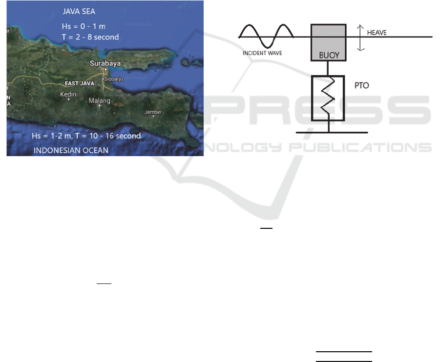
Figure 1: Wave characteristics in East Java.
From figure 1, the south coast has a significant
wave height Hs = 1-2 m with a wave period T = 10-
16 seconds. Whereas on the north coast has a
significant wave height Hs = 0 - 1 m with a wave
period T = 2 - 8 seconds (Warpindyasmoro, 2018).
The energy produced by ocean waves (Goncalves,
2014; Atan, et.al, 2016) is
𝑃
𝐻
𝑇 (1)
Where ρ is the density of seawater (kg/m3), g is
the gravitational acceleration (m/dt2), Hs is the
significant wave height (meter) and T is the wave
period (seconds). By using the equation (1), the
potential of electrical energy on the coast of East
Java can reach 232 MWh/m/year (Warpindyasmoro,
2018). Energy potential is large enough to be
developed further.
Characteristic differences between waves on the
north coast (Java Sea) and the south coast
(Indonesian Ocean), especially related to wave
periods, to optimize the energy produced, floating
objects are needed as Wave Energy Converter
(WEC) which has the maximum Response
Amplitude Operator (RAO) according to the wave
period at each wave location at the sea.
3 POINT ABSORBER
MODELLING
One WEC that can be directly connected with a
generator is a point absorber. Parameters that need to
be considered when designing a point absorber are
shape, length, volume, mass, draft, center of weight,
buoyant force and moment of inertia (Nielsen, et.al,
2014). Modelling of absorber points can be seen in
Figure 2.
Figure 2: Point absorber modelling.
The movement of the point absorber is limited to
moving only in the z axis, so that the equation of
motion from the point absorber according to
Newton's Law (Pecher, 2017) is:
𝑚
𝐹
𝐹
𝐹
𝐹
𝐹
(2)
Where m is the mass of floating objects, (d^2
z)/(dt^2 ) is the acceleration of floating objects in the
direction of the z axis, Fex is exciting force, Frad is
radiation force, Fres is a hydrostatic restoring force,
Fdamp is the external damping force , Ftun the buoy
tuning force to phase-control. Because the point
absorber model uses the mass-spring-damper model,
the natural frequency of the floating object is
𝜔
(3)
where k is the hydrostatic restoring coefficient,
m is mass of the buoy, ma (ω) is added mass and
msup is supplementary mass. Because the context
ISOCEEN 2018 - 6th International Seminar on Ocean and Coastal Engineering, Environmental and Natural Disaster Management
88
for waves is a period, natural period parameter will
be used which is the opposite of the natural
frequency. The development of point absorber has
been done to obtain the largest PTO (Falnes and
Hals, 2012; Shadman, 2018).
4 RESULTS AND DISCUSSION
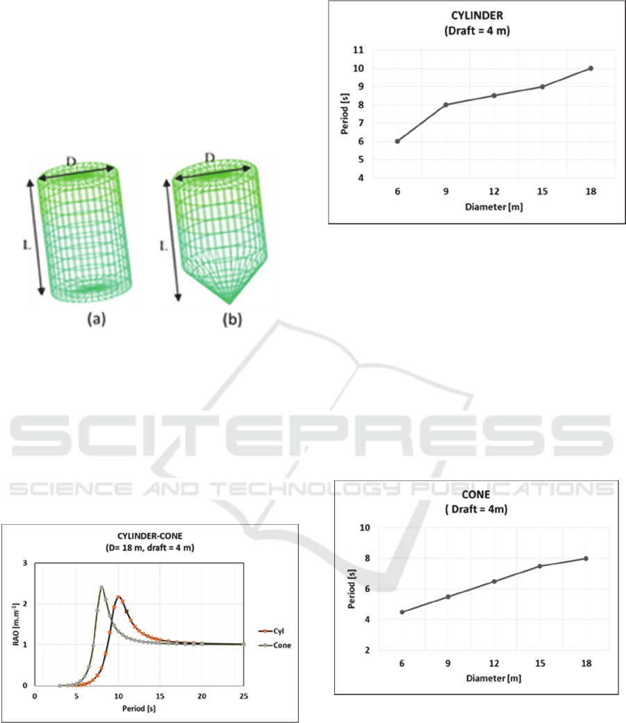
Figure 3: Model of point absorber: (a) cylinder, (b) cone.
In this study two point absorber models were made,
namely cylindrical and cone shaped like Figure 3.
The size of each model is L = 1.5 D, where D is the
diameter. The diameter of the model varied, D = 6,
9, 12, 15 and 18 m. Figure 4 shows the comparison
of RAO between cylinders and cones for D = 18 m
with a 4 m draft. It appears that the maximum RAO
on the cylinder occurs at a greater period than the
maximum RAO at the cone.
Figure 4: Comparison of maximum RAO in cylinders and
cones.
To find out the relationship between the diameter
of the floating object and the wave period that
produces the maximum RAO, the diameter of the
floating object is simulated for diameter 6, 9, 12, 15
and 18 m. For cylindrical floating objects can be
seen in Figure 5.
Figure 5: Relationship between diameter and period to
produce maximum RAO for cylinder shape.
From Figure 5, it appears that the greater the
maximum floating diameter of the RAO object will
occur at the higher wave period. For maximum
diameter (D) 6-18 m, RAO occurs in the wave
period (T) 6-10 seconds. To produce maximum
RAO in a wave period of more than 10 seconds can
be done by increasing the diameter of the floating
object. For locations that produce waves with a wave
period of 10-16 seconds, such as on the southern
coast of the Java Sea (Indonesian Ocean) can use
cylindrical floating objects as point absorber for
WEC to produce maximum mechanical energy.
Figure 6: Relationship between diameter and period to
produce maximum RAO for cone shape.
Meanwhile for conical floating objects, as shown
in Figure 6, the maximum RAO with a diameter (D)
of 6-18 m occurs in the period of wave (T) 4-8
seconds. By reducing the diameter, the maximum
RAO will be obtained in a period smaller than 4
seconds. Thus the conical floating object can be used
as a point absorber in the WEC to be applied in
Wave Energy Conversion with Floating Objects for the Coast of East Java
89

locations with small wave periods (2-8 seconds)
such as on the north coast of East Java (Java Sea).
5 CONCLUSION
An overview of the cylindrical and cone shaped
point absorber has been carried out. Point absorber
with cylindrical floating objects produces maximum
RAO over a larger period than cone-shaped floating
objects. To produce the maximum RAO, the greater
the maximum RAO floating diameter will occur in
the larger period. Point absorber with cylindrical
floating objects 6 - 18 m in diameter can produce
maximum RAO in the wave period of 6 - 10
seconds. By enlarging the diameter, this shape is
more suitable for locations with higher wave periods
such as on the southern coast of East Java
(Indonesian Ocean). While the cone-shaped point
absorber can produce maximum RAO in the 4 - 8
second wave period. By reducing the diameter of
floating objects, this shape is more suitable to be
applied on the north coast of East Java (Java Sea).
ACKNOWLEDGEMENTS
This research was funded by the Directorate of
Research and Community Service of the Directorate
General of Strengthening Research and
Development of the Ministry of Research,
Technology and Higher Education in accordance
with the Agreement on the Implementation of
Research Program Implementation Number:
002/SP2H/LT/K7/KM/2018, 26 February 2018.
REFERENCES
A. Pecher, 2017. Handbook of Ocean Wave Energy, 7.
B. Drew, A. R. Plummer, and M. N. Sahinkaya, 2009.
JPE, 223, 887.
G. A. Aggidis and C. J. Taylor, 2017. IFAC-
PapersOnLine, 50, 1.
H. Saptono Warpindyasmoro, 2018. MATEC Web Conf.,
177, 01018.
I. López, J. Andreu, S. Ceballos, I. M. De Alegría, and I.
Kortabarria, 2013. Renew. Sustain. Energy Rev., 27,
413.
J. Falnes and J. Hals, Philos., 2012. Trans. R. Soc. A Math.
Phys. Eng. Sci., 370, 1959.
K. Nielsen, M. M. Kramer, F. Ferri, A. S. Zurkinden, and
M. Alves, 2014. Overview of wave to wire models,
Aalborg University.
K. Ravinesh, M. Rafiuddin, M. Asid, and Y. Lee, 2016.
JOES, 1, 77.
M. Faizal, M. R. Ahmed, and Y. H. Lee, 2014. Adv. Mech.
Eng.
M. Gonçalves, P. Martinho, and C. Guedes Soares, 2014.
Renew. Energy, 68, 774.
M. Shadman, S. F. Estefen, C. A. Rodriguez, and I. C. M.
Nogueira, 2018. Renew. Energy, 115, 533.
P. Frigaard, T. L. Andersen, and L. Margheritini, 2008.
8th International Congress on Advances in Civil
Engineering, 15.
R. Atan, J. Goggins, and S. Nash, 2016. Energies, 9, 11.
ISOCEEN 2018 - 6th International Seminar on Ocean and Coastal Engineering, Environmental and Natural Disaster Management
90
