Adaptive Underwater Optical Wireless Sensor Network Using LED-
Based Visible Light Communications
Xin Lin
Nakagawa Laboratories, Inc. and NAKATEN, 2-9-8 Ryogoku, Sumida-ku, Tokyo, Japan
Keywords: underwater optical wireless sensor network, visible light communication, wavelength adaptation control,
LED.
Abstract: An adaptive underwater optical wireless sensor network (AUOWSN) is proposed for marine environment
development and seafloor resources observation. The method of LED-based visible light communication
(VLC) is employed for creating the wireless network among the sensor nodes, and each sensor node is a
VLC transceiver. The LED is incoherent source, it can neither damage the marine creatures like as a
coherent laser nor lose the inherent high speed of light yet. The wavelength-adaptation-control technique is
used for seawater turbidity and marine environment which have the spatiotemporal change. The
effectiveness of proposed AUOWSN is demonstrated in the experiments of underwater one-to-one image
transmissions.
1 INTRODUCTION
A wireless sensor network (WSN) consists of
multiple spatially distributed wireless terminals.
Each wireless terminal is an autonomous sensor
node. And each sensor node equipped with a
wireless transceiver, a microprocessor, and a battery
or energy harvesting device. The sensor nodes of a
WSN are scattered in a specific physical space to
collect information from these wireless sensors
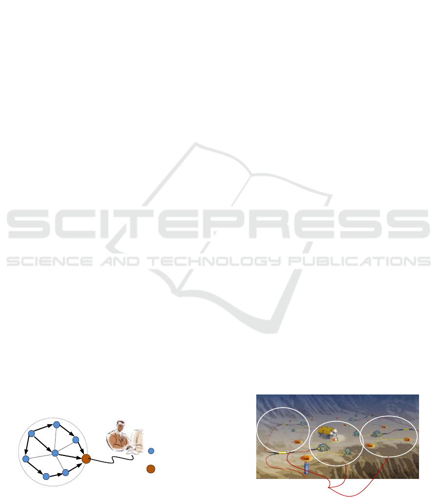
(Dargie and Poellabauer, 2010). Figure 1 shows a
mesh-type WSN. Because the WSN is a multipoint
simultaneous measurement system, hence it is
effective for grasping distribution changes of
environmental situations and physical phenomena.
And it is also one of core technologies used in
current Internet-of-Things (IoT) system (Ootsuka
and Kazama, 2014).
Figure 1: Mesh-type WSN.
On the other hand, the expansion of human
activities in marine environments such as the
monitoring and exploration of the ocean, offshore oil
field exploration and so on make the needs for
underwater WSN (UWSN) is increasing (Detweiller
et al., 2007). Like this that the developments of
marine environment and resources have many tasks
for the observations and analysis of many
phenomena including marine physics, marine
chemistry, marine biology, and so on. And data
among these different fields are related to each
other. Therefore, how to construct a smart UWSN is
also interesting and important in the aquatic world
with multi-data, so, data between different detectors
can mutually use and reference. Figure 2 shows a
detector net in a seafloor observatory.
Figure 2: A detector net in a seafloor observatory.
sensor node
gateway
sensor node
sensor 1
for biology
sensor 2 for
physics
sensor 3 for
chemistry
seafloor observatory
data in different fields
222
Lin, X.
Adaptive Underwater Optical Wireless Sensor Network Using LED-Based Visible Light Communications.
DOI: 10.5220/0008187902220227
In The Second International Conference on Materials Chemistry and Environmental Protection (MEEP 2018), pages 222-227
ISBN: 978-989-758-360-5
Copyright
c
2019 by SCITEPRESS – Science and Technology Publications, Lda. All rights reserved
However, the techniques of conventional
terrestrial WSN to the marine environments have
intrinsic difficulties. In fact, the major obstacle in
using radio for underwater communication is the
severe attenuation due to the conducting nature of
seawater. In particular, the attenuation is very high
for high-frequency radio waves and, since the
current terrestrial technology for wireless
communication is often based on high frequency in
the order of Gbps, so it is practically impossible to
use terrestrial techniques in underwater application.
In this paper, an underwater optical WSN
(UOWSN) is proposed by using the visible light
communication (VLC) technique. And the method
of wavelength-adaptation control is used for
seawater turbidity and marine environment which
have the spatio-temporal change.
2 UNDERWATER OPTICAL WSN
An alternative to radio wave communication is using
visible light wave. Seawater exhibits a window of
reduced absorption in the visible spectrum, as shown
in Figure3 (Nakao, 1987). Particularly between 400-
650nm, where water is relatively transparent to light
and absorption takes its minimum value. Also,
because the inherent high bandwidths and space
divisionality of the light wave, make the techniques
of underwater optical wireless communication
(UOWC) the most important approach to construct
the UWSN (Ghelardoni et al., 2012).
Figure 3: Absorption coefficients of electromagnetic wave
in the water.
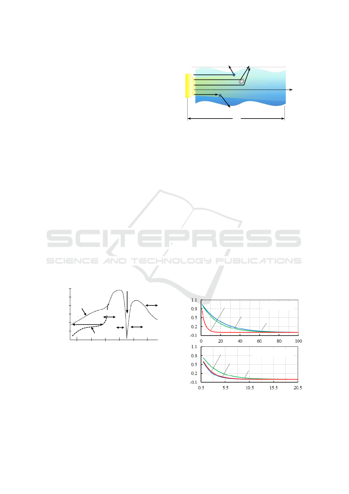
2.1 Underwater Optical Channel
Study of underwater optical channel is important for
creating a UWSN. Figure 4 shows the physical
model of visible light propagation in seawater.
Figure 4: Physical model of light propagation in seawater.
Natural seawater is a translucent substance with
a lot of micro particle and water molecule. The
performance of the UOWSN relies on how well light
propagates though this “translucent substance”.
When incident light I
0
passes through the seawater,
it become an attenuation light I
a
after a propagation
distance L due to absorption and scattering of micro
particle and water molecule. The mathematical mode
for this attenuation process can be written as
(1)
(2)
where
is wavelength of the incident light, K() is
total attenuation coefficient of seawater, a() and
b() is the absorption and the scattering coefficient,
respectively. The experimental data of K() in
horizontal light propagation direction are given by
Hulbert et al in 1945. Using these data, spectrum-
intensity attenuations for different seawater types
that correspond to Eq. (1) are obtained and plotted in
Figure5
Figure 5: Spectrum-intensity attenuation for different
seawater types in horizontal direction.
visible light
10
8
10
6
10
4
10
2
10
0
10
-2
10
-4
absorption coefficient
(dB/m)
X ray
seawater
microwave
radio wave
ultraviolet
infrared
distilled water
10
3
10
6
10
9
10
12
10
15
10
18
frequencies (Hz)
light intensities (W)
distances (m)
bay (high turbidity)
red (650nm)
green (550nm)
blue (450nm)
pure seawater
red (650nm)
green (550nm)
blue (450nm)
seawater
(translucent substance)
scattering
incident light (I
0
)
micro particle
attenuation light (I
a
)
water molecule
absorption
converted energy
L
Adaptive Underwater Optical Wireless Sensor Network Using LED-Based Visible Light Communications
223
For pure seawater type on upside graph of Figure
5, the absorption is dominated almost by the
attenuation of seawater molecule, the region of ideal
wavelength with lowest attenuation for visible-light
propagation is within the blue-green band between
400nm and 500nm. In case of high-turbidity bay on
bottom of Figure5, the total absorption in visible-
light band is dominated by the combination of
organic and inorganic particles, the ideal
transmission wavelength is shifted from blue-green
wave band towards green-yellow band around 550-
600nm.
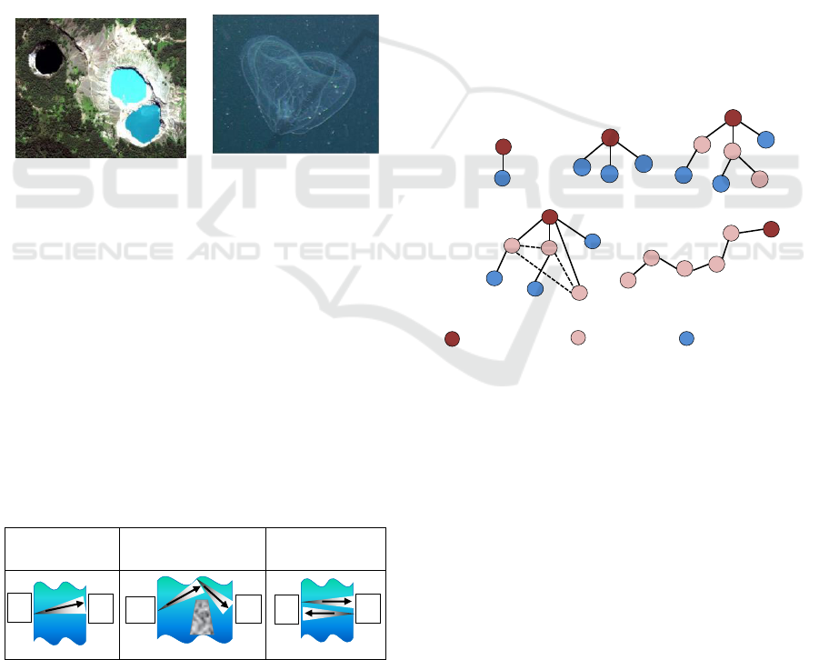
On the other hand, the spatiotemporal change of
seawater color (Figure 6(a)) is also an intrinsic noise
which can affect light propagation. And the marine
snow (Figure 6(b)) in deep sea is an external noise
which able disrupts the optical link because it is a
visually observable enough large particulate organic
materials.
(a) (b)
Figure 6: Noises in underwater optical channel: (a)
spatiotemporal change of seawater color, it is an intrinsic
noise (picture by Johnson, The Univ. of Warwick) and (b)
marine snow in Sagami bay of Japan (picture by Kitamura,
2006).
2.2 Underwater Link Configuration
Underwater link configuration between sensor nodes,
and what is the difference between underwater links
and terrestrial links in a VLC system also should be
considered. Typical underwater diffuseness link
configurations between a transmitter and a receiver
are tabulated in Table 1 (Johnson et al., 2014).
Table 1: Typical diffuseness links for UOWC.
LOS
diffuseness
non-LOS
diffuseness
LOS diffuseness
retroreflector
Line of sight (LOS) refers to the ability to see the
transmitter from the receiver. The LOS link is the
simplest type which a direct link between the
transmitter (Tx) and receiver (Rx). Non-LOS link
uses reflections from the sea surface to overcome
underwater obstacles. LOS retroreflector link is
useful when bidirectional communication is
required, but the receiver is too low power to
support a full transceiver for underwater sensor
nodes. Theoretically, all these configurations have
enough good bit error rate (BER) and are viable for
short-range of under 15m underwater data
transmission (Arnon, 2010).
For turbid nature seawater, the attenuation of
light propagation is dominated by scattering, a wide
field-of-view (FOV) angle of transmitter can
compensate for the increased attenuation. Incoherent
visible-light LED (Light Emitting Diode) is most
suitable for this diffuseness-link application.
2.3 Constructing an Adaptive UOWSN
Such as a WSN in terrestrial environment, a WSN in
marine environment also has different types to favor
different applications. Figure 7 shows link
topologies of different UWSN types.
Figure 7: The link topologies of different UWSN type.
In order to construct a UOWSN which is viable
to work in a seafloor observatory (see Figure 2), the
mesh-type WSN topology is adopted to multipoint
simultaneously measure and transmit data from
different detectors and share these data each other
without human operations. The wavelength-
adaptation control technique (Lin, 2017) is used to
help overcome the “spectrum-intensity attenuation”
which shown in Figure 5 in different seawater types.
The links between sensor nodes are “LOS
diffuseness” type configuration because it is easier
to implement and most energy efficient for UOWC.
The UOWSN with mesh type that is proposed in
this work is shown in Figure 8. It consists of one
gateway sensor node (i.e. main node) and multiple
sensor nodes (i.e. sub nodes). Each node is
connected to other nodes to make a mesh; such,
Tx
Tx
Rx
Rx
Tx
Rx
A
B
C
gateway node
end-device node
router node
star type (1 to n)
tree type
linear type
mesh type
one to one type
MEEP 2018 - The Second International Conference on Materials Chemistry and Environmental Protection
224
multiple communication paths can be generated,
which cooperatively pass their data through the
mesh network to the land-base station. The distances
between the sensor nodes are about 3-10m. Data
from each sensor node are long-distance transmitted
to a land-base station via the gateway node. The link
between gateway node and land-base station is
optical fiber.
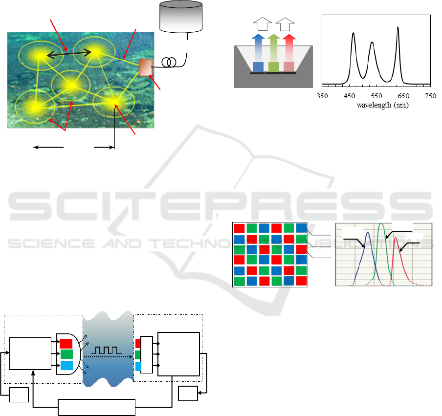
Figure 8: The mesh-type UOWSN.
Each sensor node is a wavelength-adaptation
LED-based VLC transceiver, and its control
principle as shown in Figure 9. Each VLC
transceiver as a sensor node is installed into a
seafloor detector for bidirectional data transmission.
The links between these sensor nodes are optical
seawater channels. The space division and visibility
of visible light can ensure each sensor node is
independent and identifiable both in space and time.
Figure 9: LED-based VLC transceiver with wavelength
adaptation.
In order to reach the wavelength-adaptation
control, a multi-chip white LED is used as the light
source of the transceiver. Figure 10 is a white LED
module with three chips of R(red), G(green), and
B(blue) which is used in this system. Each chip has
an independent wavelength peak, which can as a
separate channel for different seawater-types
adaptation control. The LED is incoherent source, it
can neither damage the marine creatures like as a
coherent laser nor lose the inherent high speed of
light yet. Also, it can as a lighting equipment for
underwater lighting.
Figure 10: Three-chips white LED module.
To detect three-colors light from LED source
with high accuracy simultaneous, at receiving side
of the transceiver, a photodiode (PD) with three-
primary-colors sensor chips is used, as shown in
Figure 11. Three sensor chips are arranged in mosaic
shape on the light detection surface of PD.
Figure 11: Three-sensors color photodiode.
The baseband intensity modulation is main
carrier techniques employed in optical wireless
communication. The on-off keying with no return to
zero (OOK-NRZ) and the pulse position modulation
with L levels (L-PPM) are two most common
schemes of the baseband intensity modulation
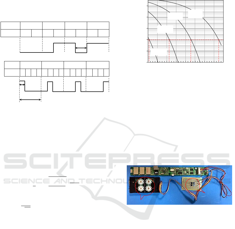
(Manea et al., 2011). Figure 12 shows the coding
methods of OOK-NRZ and 4-PPM (L=4). The
OOK-NRZ transmits data in a bit unit of binary “0”
and “1”, and the 4-PPM transmits data in a symbol
unit which is a string of 4 bits. Although OOK-NRZ
scheme has higher data transmission rate, L-PPM
yields an average power requirement that decreases
steadily with increasing L. This decreased average
power requirement makes L-PPM more suitable to
land-base
station
bidirectional communication
optical channel
optical fiber
gateway
sensor node
(main node)
space division
sensor node
(sub node)
3~10m
300 400 500 600 700 800
wavelength (nm)
spectrum
red
green
blue
wavelength adaptation
data
LED
R
LED
G
LED
B
Transmitter
modulation
&
control
Receiver
de-
modulation
&
control
R
color PD
G
B
data
optical
seawater
channel
illumination
&.signal
light-emitting principle
white light
LED chips
B
G
R
R: 620nm
G: 520nm
B: 470nm
spectrum
B-PD
G-PD
R-PD
photo-detection surface
Adaptive Underwater Optical Wireless Sensor Network Using LED-Based Visible Light Communications
225
underwater data transmissions. Especially, for deep-
sea environment, more low power consumption is
required.
data
0 0
0 1
1 0
1 1
OOK-NRZ
0
0
0
1
1
0
1
1
data
0 0
0 1
1 0
1 1
4-PPM
1
0
0
0
0
1
0
0
0
0
1
0
0
0
0
1
Figure 12: The coding methods of OOK-NRZ and 4-PPM.
The underwater digital optical wireless
communication is employing binary encoding to
accomplish optical data transmission and using BER
parameter to describe the optical seawater channel
performance. BER is a conditional probability; it
must be averaged over the probability-density
function of random digital signals to determine the
unconditional BER. The BER of L-PPM given by
(3)
(4)
where SNR is the mean signal-to-noise ratio in the
seawater channel and electronic circuit of
communication system. By using Eq. (3) and (4), the
SNR requirement of L-PPM scheme to reach a
certain BER can be calculated and the BER
performances for different L values are plotted in
Figure 13. The SNR requirement is decreased with
increasing L, for example, to reach BER of 10
-8
, the
SNRs of L=2, 4, 8, 16 are about 15, 9, 4.5, and 0.5,
respectively. The larger L can obtain better BER
performance. However, an increase in the L causes a
decrease in the communication speed. L=4 is a
preferred value employed in common underwater
optical wireless communications due to 4-PPM
scheme has appropriate efficiency both in BER and
speed.
Figure 13: BER versus SNR for L-PPM with different L
values.
3 EXPERIMENTS AND RESUTLS
Using the developed LED-based transceiver which
shown in Figure 14, the experiment for underwater
bidirectional image (640×480 pixels) transmissions
is implemented between a one-to-one link. The
principles of this transceiver have been described in
Figure 9-11. The 4-PPM method is used for
baseband light intensity modulation.
Figure 14: The prototype of LED-based VLC transceiver.
The results of image transmission with different
wavelength light are shown in Figure 15. In the
experiment, the transceiver is placed in a transparent
waterproof container which has high visible-light
transmissivity of about 93%, and then, the
waterproof container is placed into a water tank
which has 600mm width. Turbidity of water at the
tank is adjusted by using white-sand particles. A
water-flow equipment is used to generate dynamic
flow water which similar to natural water. The blue-
green light at 490nm wavelength and green-yellow
light at 590nm are used to demonstrate the data
transmission effectiveness of the proposed
wavelength-adaptation control method in lower-
and higher-turbidity water. Stable data transfer rate
is 5Mbps and BER less than 10
-8
.
1E-12
1E-10
1E-08
1E-06
1E-04
1E-02
0 2 4 6 8 10 12 14 16
SNR (dB)
BER
2-PPM
4-PPM
8-PPM
16-PPM
1 symbol
1 bit
LED source
PD
detector
1 bit
MEEP 2018 - The Second International Conference on Materials Chemistry and Environmental Protection
226
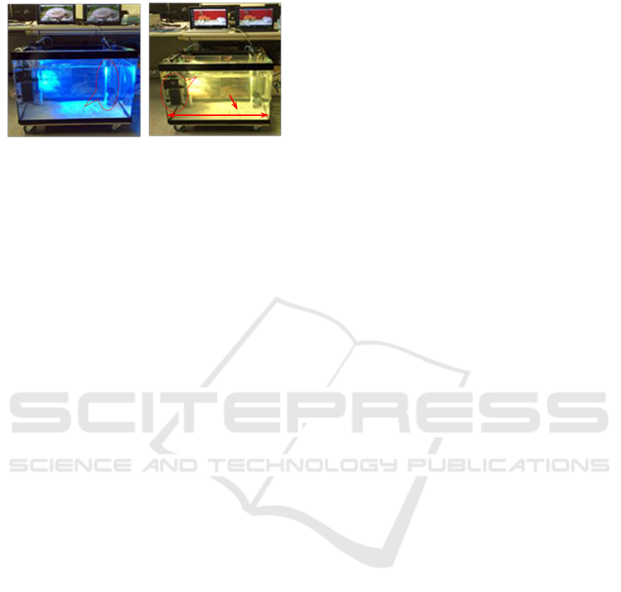
Figure 15: The results of underwater one-to-one image
transmissions with different light wavelength.
4 CONCLUSIONS
The purpose of this study is to effectively develop
marine environments and resources, and the
incoherent LED is an attractive light source because
it not only can transmit data and never damage the
marine creatures, but also can as a lighting
equipment for underwater lighting. So, by using the
techniques of LED-based VLC, a mesh-type
UOWSN with wavelength-adaptation-control
function has been constructed for data transmission
in aquatic environment. A prototype of LED-based
VLC transceiver has been developed to perform the
one-to-one image data transmission experiments
with different light wavelength, and good BER and
data rate have been obtained both in lower-turbidity
and higher-turbidity water. Further studies include
that:
underwater optical experiments for one-to-
many and many-to-one data transmissions;
underwater link methods with low power
consumption;
vertical direction characteristics of optical
seawater channel.
ACKNOWLEDGEMENTS
This work was supported by Ministry of Land,
Infrastructure, Transport and Tourism, Japan.
REFERENCES
Arnon, S., 2010. Underwater optical wireless
communication network. Optical Engineering, vol. 49,
pp. 1-6.
Dargie, W., Poellabauer, C., 2010. The book,
Fundamentals of wireless sensor networks: theory and
practice. Wiley.
Detweiller, C., Vasilescu, I., Rus, D., 2007. An underwater
sensor networks with dual commucations, sensing, and
mobility. OCEANS 2007, pp. 1-6.
Ghelardoni, L., Ghio, A., Anguita, D., 2012. Smart
underwater wireless sensor networks. IEEE 27
th
Convention of Electrical and Electronics Engineers in
Israel, pp.1-5.
Johnson, L. J., Jasman, F., Green, R. J., Leeson, M. S.,
2014, Recent advances in underwater optical wireless
communications. Underwater Technology, vol. 32, no.
3, pp.167–175.
Lin, X., 2017. Underwater wireless communication system
of adaptation wavelength using visible light. IEICE
Trans. Fundamentals, vol. E100-A, no. 1, pp. 185-
193.
Manea, V., Dragomir, R., Puscoc, S., 2011. OOK and
PPM modulations effects on bit error rate in terrestrial
laser transmissions. Telecomunicatii Anul LIV, nr.2,
pp. 55-61.
Nakao, S., 1987. Attenuation of electromagnetic waves in
seawater. Defense Technology, pp. 22-30.
Ootsuka, H., Kazama, H., 2014. A study of system
integration related to advanced IT networks in IoT.
IEICE technical report, vol. 114, no. 166, pp. 169-176.
blue-green light (490nm)
Tx image Rx image
Tx
Rx
transceiver
green-yellow light (590nm)
600mm
water-flow equipment
white sand
Tx
Rx
Tx image Rx image
Adaptive Underwater Optical Wireless Sensor Network Using LED-Based Visible Light Communications
227
