
A Metamaterial Absorber for Microwave De-icing of Wind Turbine
Blades and Its Electromagnetic and Thermal Properties
Zehai Zhang
1*
, Jing Wang
2
, Junpu Ling
1
and Yuzhang Yuan
1
1
College of Advanced Interdisciplinary Studies, National University of Defense Technology(NUDT) ,Changsha, China
2
College of Liberal arts and Sciences, National University of Defense Technology(NUDT) ,Changsha, China
Keywords: Metamaterial Absorber; De-icing; Wind turbine blade; Microwave heating; Multi-physical simulation
Abstract: The icing of wind turbine blades in cold climates may reduce the power generation efficiency, shorten the
life of the blades and even bring safety hazard. De-icing of wind turbine blades is very necessary. The
current technical means such as heating resistance, warm air, and other means of de-icing have various
limitations, and no mass produced commercial wind turbine blade de-icing system are available currently.
Microwave heating has the characteristics of selectivity, non-contact and rapid heating, and is a potential
and flexible de-icing way of wind turbine blades. In this paper, a kind of metamaterial absorber (MA) which
can strongly absorb 2.45GHz microwave is designed. It can absorb the incident microwave and then convert
the microwave energy into heat. Multi-physical simulation is carried out to analyse the heat generation,
thermal distribution and temperature rise of the MA under microwave radiating. This preliminary simulation
results show that MA is possible to be used in microwave de-icing of wind turbine blades.
1 INTRODUCTION
Wind power as a green energy is clean and
renewable. According to the report of Technical
Research Centre of Finland (VTT, 2013), wind
power capacity is growing rapidly in the cold
climates of the world, and between 45 and 50
gigawatts of wind power would be built in cold
climates by 2017 for higher winds and proper
density of cold air. However, turbine blades are
highly susceptible to icing in these areas. Icing may
significantly reduce the aerodynamic properties of
blades and lead to mechanical failures, safety hazard
(Seifert et al., 2003), and possible stoppage of
operation (Hochart et al., 2010). Lots of wind
turbines with no de-icing equipment will only stop
to wait for ice to melt naturally. De-icing of wind
turbine blades is very necessary.
Parent and Ilinca
(Parent and Ilinca, 2011)
provided a critical review of de-icing techniques for
wind turbines include passive and active systems.
Heating resistance and warm air are most used
active techniques in de-icing. Due to direct heating,
the heating resistance systems have high efficiency
(up to 100%) (Battistil et al., 2005) and are mainly
used in current. The heating materials such as carbon
fiber sheet (Xu et al., 2018), polymer electric heating
film (Shu et al., 2017, Mu et al., 2014) are studied
intensively. However, icing of run back water at the
edges of the heating elements may occur often in the
heating resistance system, and there is no flexible
once the heating elements were buried well. Warm
air system had also been applied in wind turbines de-
icing (Zhao et al., 2016). However, the warm air
needs to heat the whole shell of the wind turbine
blade from the inner surface of the shell. As the shell
structures have small coefficient of thermal
conductivity and becoming larger and thicker, the
efficiency becomes very low. New de-icing
techniques are called for.
Microwave heating is one of the active de-icing
methods, and has the characteristic of selective,
volumetric and rapid. Microwave heating is
expected to realize wireless, scanning and rapid de-
icing, and is expected more flexible than the heating
resistance de-icing. One of the key of microwave
heating is to find materials absorbing microwave
strongly and with thin thickness as much as possible.
L. Feher et al (Feher et al., 2009) studied microwave
de-icing with carbon fiber reinforced plastic (CFRP)
aimed to be applied on aircraft, and demonstrated
selective, non-contacted and volumetric heating of
microwave experimentally. Johansson et al
(Johansson et al., 2015) demonstrate microwave
Zhang, Z., Wang, J., Ling, J. and Yuan, Y.
A Metamaterial Absorber for Microwave De-icing of Wind Turbine blades and its Electromagnetic and Thermal properties.
DOI: 10.5220/0008187802170221
In The Second International Conference on Materials Chemistry and Environmental Protection (MEEP 2018), pages 217-221
ISBN: 978-989-758-360-5
Copyright
c
2019 by SCITEPRESS – Science and Technology Publications, Lda. All rights reserved
217
heatable CNT coatings for wind turbine blade de-
icing. The carbon fiber or CNT coatings absorb
microwave but not totally, thus reflection and
transmission of microwave power may cause
microwave leakage or reduce power efficiency.
This paper presents a metamaterial absorber
( MA ) different from carbon fiber and CNT
coating for wind turbine blades de-icing under
microwave radiating. The heating source may be
industrial magnetron or solid state microwave
amplifier. The reflection of -26.0dB at 2.45GHz is
reached with MA thickness of 2mm. An intuitive
impression of electromagnet-thermal conversion of
MA under microwave radiating is also presented.
This paper is organized as follows: The first part
is introduction. The second part presents the design
of electromagnetic absorbing property. The third
part studies the electromagnet-thermal conversion
under microwave radiating with multi-physical
simulation software. Temperature distribution is also
given. The forth part concludes the paper. These
efforts have laid a solid foundation for further study
of the MA.
2 ELECTROMAGNETIC DESIGN
2.1 MA for De-icing of Wind Turbine
Blades under Microwave Radiating
The original form of MA is Landy’s Perfect
Metamaterial Absorber, which is consisting of two
distinct metallic elements and a dielectric layer
between them (Landy et al., 2008). Through fine
adjusting of the metallic elements, the MA can
absorb the incident microwave at a single frequency
point almost totally. Gradually, whole back metallic
layer replaces the split cut wires and various front
metallic patterns emerge. The simple form made the
design of perfect absorption easily achieved. In this
situation, the double-facet Copper Clad Laminate
(CCL) was usually used to fabricate MA.
The MA absorbs the incident microwave within
a small thickness which usually less than one tenth
of the operating wavelength. The small thickness
and thereby a small volume made MA little self-
heated energy consumed when used for microwave
heating. Thus the MA is suitable for microwave de-
icing.
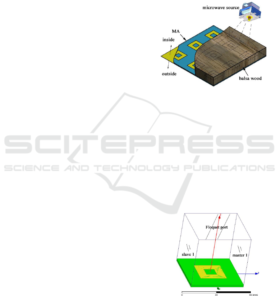
From a concept view, the microwave source can
be arranged inside the blade and fixed on the web.
The microwave radiated from source by antenna and
penetrates the balsa wood (heat insulator and
transparent to microwave) or other supporting
materials and reached onto the MA, as schematically
shown in Figure 1. Due to the MA has entire back
metal film and covers the entire outer surface of the
blade, no microwave can leak outside and thus the
microwave seldom has impacts on environment
around the turbine.
Figure 1: Schematic diagram of part of wind turbine blade
under microwave heating.
2.2 The Electromagnetic Property
Design of the MA
As higher energy conversion efficiency is expected,
the absorption rate of microwave is expected as high
as possible. The design of the MA is aimed to absorb
the incident microwave totally at given frequency
2.45GHz. HFSS (Ansoft Inc, 2009)
simulation study
is carried out to achieve the goal. Hollow square ring
is adopted as the front metallic pattern of the MA
due to its simple and central symmetric property. A
single unit of the periodic model is built. The model
and the above air box in HFSS are shown in Figure 2.
Top layer (yellow): hollow square copper film ring;
Middle dielectric layer (green): FR-4, 2mm;
Back film (unseen): copper film
Figure 2: Model of the hollow square MA unit built within
HFSS.
MEEP 2018 - The Second International Conference on Materials Chemistry and Environmental Protection
218
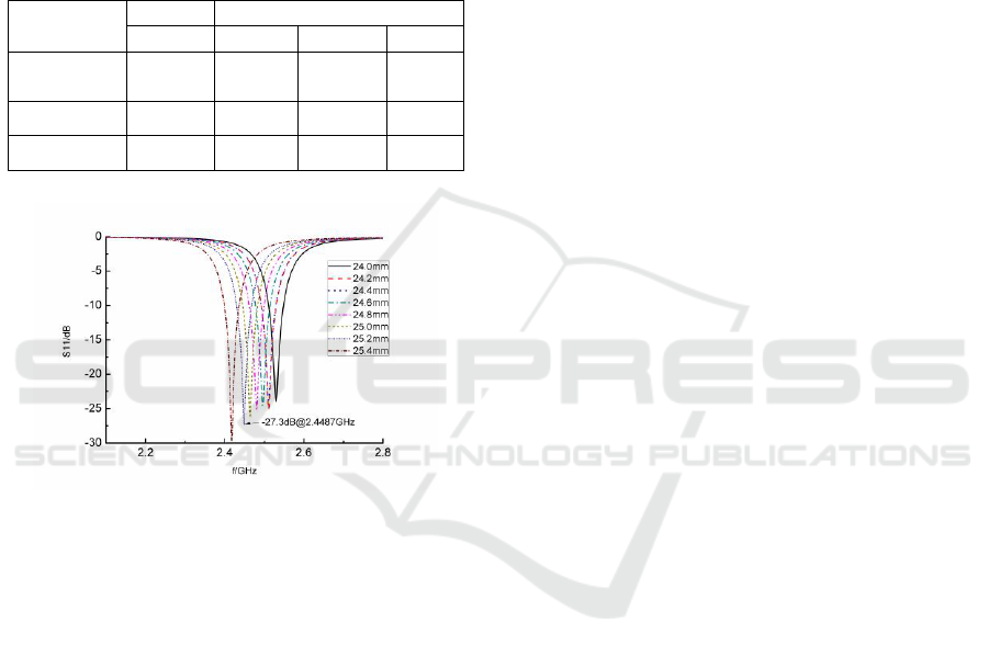
Master-slave boundaries are imposed on each
pair of the opposite side faces of the domain to
match the periodical model. Floquet port is imposed
on top face of the computational domain. The
material of the metallic ring and the back film are
both 18μm copper films with conductivity of
5.998e7 S/m. The middle dielectric layer is FR-4
with 2mm thickness. The relative permittivity ε
r
and
permeability μ
r
are 4.3 and 1.0, respectively. The
dielectric loss factor of FR-4 is 0.02.
Table 1:Components parameters of the optimized MA.
Components
layers
Parameters(mm)
material
Thickness
L_Outer
L_Inner
Hollow square
ring
copper
0.018
25.2
10.0
Mid-dielectric
FR-4
2.0
50.0
-
Back film
copper
0.018
50.0
-
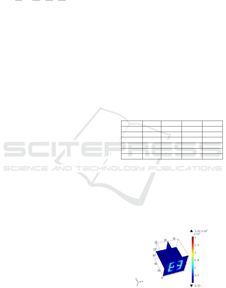
Figure 3: Parameter swept S11 curves of the MA.
Geometric parameters of the MA affect the
absorb frequency point and absorbing intensity. The
resonant frequency was mainly governed by the
length of central line of the metallic ring, while the
absorbing intensity is mainly affected by the
thickness and the dielectric loss of the dielectric
layer (Pang, 2013). The following optimization
keeps in line with these principles.
In order to obtain a MA as thin as possible, the
thickness of the MA is expected no greater than
2mm. Besides, the period of the unit is expected to
be kept integer for convenience. The aim of
optimization is to obtain a higher absorption rate
while thickness and period of the MA kept fixed.
The outer and inner side lengths of the hollow ring
are selected as variables for optimization. The
genetic algorithm built-in HFSS about the outer and
inner side lengths with their physical limits range for
better absorption at 2.45GHz are carried out, while
other parameters are kept unchanged. The optimized
L_outer and L_inner and other parameters are shown
in Table 1.
Under the optimized parameters, the S
11
reaches
-26.0dB at 2.45GHz when L_outer=25.2mm, while
the best absorb point is located at 2.4487GHz and
the S
11
reaches -27.3dB, the curves of S
11
with swept
L_outer as shown in Figure 3.
3 MULTI-PHYSICAL
SIMULATION
The MA absorbs and converts microwave energy
into heat. With the optimized parameters of the MA
obtained above, we investigate the electromagnet-
thermal conversion and energy efficiency with
COMSOL (COMSOL Inc, 2012), a commercial
simulation software suitable for multi-physical
problems.
3.1 The Simulation Model of MA in
COMSOL
A single unit model of MA similar to that in HFSS is
built with COMSOL. The back of the model was set
as an ideal conductor boundary rather than copper
film while other components kept unchanged. As the
thickness of the hollow copper ring is too small to
resolute, a transition boundary is adopted to replace
for. No meshes are built within the transition
boundary, but physical properties including
conductivity, thickness, etc are kept.
Periodic boundaries were assigned onto the side
face pairs and periodical port was assigned onto the
top face with TEM mode. The boundaries, port and
incident mode made this unit model equivalent to an
infinite plane MA radiated by plane microwave.
Balsa wood or other supporting materials are not
considered currently.
3.2 Electromagnet-thermal Conversion
The heat generated within the MA mainly come
from microwave dielectric loss in FR-4 and ohmic
loss in copper, and the loss occurs when
electromagnetic field established within the MA.
The temperature distribution of the MA will be
governed by thermal conduction and convection and
the conduction plays a major role.
To describe the time variant temperature
T(x,y,z,t) distribution of the MA unit heated by
microwave, one can accordingly solve the heat
equation for temperature T given by ( Pitchai, 2011a)
A Metamaterial Absorber for Microwave De-icing of Wind Turbine blades and its Electromagnetic and Thermal properties
219
2 2 2
2 2 2
()
T
c k T P
t x y z
(1)
Where P is the heat power density which came
from the dielectric loss and ohmic loss of the
incident microwave,
is the density of the
corresponding material, c is the specific heat
capacity and k is the thermal conductivity. The heat
power density can be expressed as a function of the
electric field component in a non-magnetic loss
medium by (Pitchai, 2011b)
'' 2
0
PE
(2)
Here E is the electric component of the
electromagnetic field built within the MA,
''
is the
imaginary part of the dielectric FR-4,
is the
angular frequency of the incident microwave and
0
is the permittivity of free space.
Equations (1) and (2) describe that temperature
distribution within the MA are governed by the
electric field strength and the distribution of the
electromagnetic field. The electric component
strength is proportional to the microwave absorption
rate of the MA, thus the energy conversion
efficiency between the microwave and heat is
strongly related to the absorption rate and the
dielectric imaginary part of the FR-4.
As the microwave is radiated by antenna and
transmitted through free space, and no extra wires
and other accessories are needed, the microwave
heating will be more flexible than electric heating.
Besides, as equation (2) implies, the heat generated
once the microwave field built up in MA, thus
microwave heating is rapid.
3.3 Multi-physical Simulation Results
The frequency of the input microwave is 2.45GHz.
In COMSOL, the default input power into the
periodical port is 1W, and the power density is
calculated of 400W/m
2
according to the cross
section area of 50mm×50mm. The tangential loss
angle of FR-4 is 0.02, while the magnetic one is 0.
The simulation duration is set as 300s and total input
energy calculated 300J. The ambient temperature
surround the model is set as 20℃.
In COMSOL, the S
11
drops to -3.25dB while the
S
11
is -26dB in HFSS, the parameters of the model
are the same. This dramatic drop results in increase
of reflection and decrease of absorbing which is
effective in heating. Furthermore, simulations show
that the relative permittivity ε
r
of FR-4 has strong
influence on microwave absorbing. Simulations are
carried out on the variation of ε
r
and the
corresponding S
11
are shown in Table 2. The power
absorbed can be calculated from S
11
, and then the
temperature rise due to the absorbed power △T
ab
can
be calculated from the following equation
0
()Q c V T T
(3)
Where Q is heat energy, V is volume. Take FR-4
into account, c=1369J/kg·K,
=1900kg/m
3
,
V=0.05×0.05×0.002m
3
and T-T
0
=△T
ab
.
The weighted mean temperature △T
ave
represents
a supposed spatial uniform temperature rise within
FR-4. It can be read directly from COMSOL, and
the power conversion efficiency
/
ave ab
TT
from microwave to heat can be calculated out. The
corresponding calculation results are summarized
and shown in Table 2. The efficiency is about 82%
when ε
r
changes. If the reflection is taken into
account, the overall efficiency η
a
drops to 21.2% to
58.1%.
Table 2: The EM-thermal conversion efficiency v.s. ε
r.
ε
r
4.1
4.2
4.3
4.4
S
11
/dB
-2.28
-5.27
-3.25
-1.30
P
ab
/W
0.41
0.70
0.52
0.26
△T
ab
/℃
9.5
16.1
12.0
6.0
△T
ave
/℃
7.8
13.4
10.0
4.9
η/%
82.1
83.0
83.3
81.6
η
a
/%
33.7
58.1
43.3
21.2
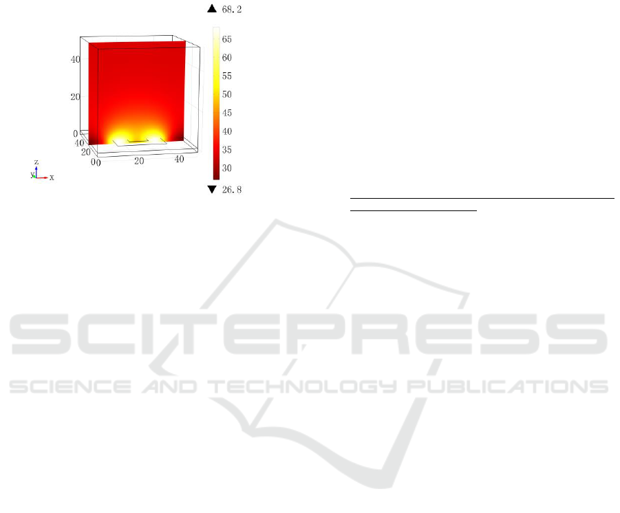
Figure 4 gives the electric field strength
distribution from a bottom view at the end of the
simulation when ε
r
=4.2. One can find that the
electric component mainly concentrates below the
copper ring, and the field distribution splits into two
parts obviously. Animation of the field versus time
reveals that the electromagnetic field acts like
standing wave, which implies the incident
microwave resonate within the MA. During this
progress, the dielectric loss and ohmic loss occurred
and the electromagnetic energy converted into heat.
Figure 4: Electric field strength(V/m) distribution.
MEEP 2018 - The Second International Conference on Materials Chemistry and Environmental Protection
220
The temperature distribution on the middle cut
plane of the simulation when ε
r
=4.2 is shown in
Figure 5. The maximum temperature is 68.2℃,
48.2℃ higher than the ambient temperature due to a
microwave power density of 400W/m
2
and heating
duration of 300s.
Figure 5: Temperature(deg) distribution on x-z cutting
section of the MA unit model (simulation duration: 300s).
This simulation is preliminary for only FR-4 is
taken into consideration in the calculation. But the
power conversion and heating figure are presented.
The overall efficiency is low in current simulation
and further investigation on improving absorbing
rate will be carried out to improve the overall EM-
thermal conversion efficiency.
4 CONCLUSIONS
In this paper, we present the idea of the wind turbine
blades de-icing with MA under microwave heating.
The design of electromagnetic absorbing property of
MA is presented. Multi-physical simulation is
carried out to analyse the heat generation, thermal
distribution and temperature rise of the MA under
microwave heating. The energy conversion
efficiency is given based on the multi physical
simulation. This preliminary simulation show that
MA is possible to be used in microwave de-icing of
wind turbine blades as a wire-less, rapid and flexible
means.
ACKNOWLEDGEMENTS
The author wants to express his gratitude to Dr. Prof.
Jelonnek for his valuable suggestions.
This work is supported partially by the National
Natural Science Foundation of China [Grant number
51706242]; and partially by Natural Science
Foundation of National University of Defense
Technology [Grant number ZK16-03-05].
REFERENCES
Ansoft Inc, 2009. HFSS online Help,Version 12.
Battistil, BrighentiA., DalSavio, S. DellAnna. 2005. Evaluation of
anti-icing energy and power require- ment for wind turbine
rotors in cold climates. BOREAS, VII, FMI, Saariselka,
Findland, p13.
Comsol Multiphysics uers’s guide. 2012. Version.4.3.
Feher, L., Seitz, T. and Nuss, V., 2009. Microwave De-/Anti-
Icing Using the Midas-Technology. Journal of Microwave
Power & Electromagnetic Energy ONLINE. Vol. 43, No. 1.
Hochart, C., Fortin, G., Perron, J. et al., 2010. Wind turbine
performance under icing conditions[J]. Wind Energy,
11(4):319-333.
http://windren.se/WW2015/WW2015_12_311_Karthauser_
ReTurn._Deicing_Micro.pdf
Johansson, K. et al., 2015. Deicing of Wind Turbines using
Microwave Technology.
Landy, N. I., Sajuyigbe, S., Mock, J. J., Smith, D. R. and Padilla,
W. J., 2008. Perfect Metamaterial Absorber. Physics
Review Letter, 100(207402).
Mu, S., Wu, R., Chen, C., Yan, S. Y., 2014. RESEARCH ON
THE THERMAL HEATING DE-ICING PROPERTIES OF
WIND TURBINE BLADE COMPOSITE PLATES BASED
ON POLYMER ELECTRIC HEATING FILM. Fiber
Reinforced Plastics/Composites (FRP/CM).(in Chinese)
Pang, Y., 2013. The Theory and Design of Metamaterial
Absorbers. Changsha: National University of Defense
Technology.
Parent, O., Ilinca, A., 2011. Anti-icing and de-icing techniques for
wind turbines: Critical review. Cold Regions Science and
Technology 65 88–96.
Pitchai, K., 2011a. Electromagnetic and Heat Transfer Modeling
of Microwave Heating in Domestic Ovens. University of
Nebraska at Lincoln. P30.
Pitchai, K., 2011b. Electromagnetic and Heat Transfer Modeling
of Microwave Heating in Domestic Ovens. University of
Nebraska at Lincoln. P13.
Seifert, H., Westerhellweg, A., Kröning, J., 2003. Risk Analysis
of Ice Throw from Wind Turbines[J]. Boreas.
Shu, L., Qi, J., Hu, Q. et al., 2017. Anti-icing Model and
Sectionalized Anti-icing Method by Electrical Heating for
Wind Turbine Blades[J]. Proceedings of the Csee,
37(5):1448-1454.( in Chinese)
Technical Research Centre of Finland (VTT), 2013. Cold climate
wind energy showing huge potential. ScienceDaily.
ScienceDaily.
Xu, B., Lu F., Song, G., 2018. Experimental Study on Anti-Icing
and Deicing for Model Wind Turbine Blades with
Continuous Carbon Fiber Sheets[J]. Journal of Cold
Regions Engineering, 32(1).
Zhao, J., Yang, W., Peng, C. et al., 2016. ANTI-ICING AND
DEICING METHOD AND DEVICE FOR HIGH-POWER
WIND TURBINE BLADES, WO/2016/037476[P].
A Metamaterial Absorber for Microwave De-icing of Wind Turbine blades and its Electromagnetic and Thermal properties
221
