
Thermal Cycling Behaviour of Dense Monolithic Alumina
Luís Guerra Rosa
1*
, José Rodriguez
2
, José C. G. Pereira
3
and Jorge C. Fernandes
1
1
IDMEC, IST, Universidade de Lisboa, Av. Rovisco Pais, Lisboa, Portugal
2
Plataforma Solar de Almería, CIEMAT, Tabernas (Almería), Spain
3
DEQ, IST, Universidade de Lisboa, Av. Rovisco Pais, Lisboa, Portugal
Keywords: Alumina, Thermal Cycling, Concentrated Solar Radiation.
Abstract: The behaviour of circular discs, with 25 mm diameter and 2 mm thickness, made of commercial high-purity
dense monolithic Alumina (RAPAL
®
100) is evaluated under three different sequences of 100 heating-cooling
cycles, all of them with a maximum temperature of 1200ºC. None of the different sequences of 100 cycles
(even the most severe one with 100 cycles applied in 77 minutes, with maximum temperature of 1200°C and
minimum temperature of 400°C) has caused noticeable alterations in the studied properties (density; Young´s
modulus of elasticity; Coulomb´s modulus of elasticity; flexural strength) measured before and after the heat
treatment.
1 INTRODUCTION
The increasing demand of ceramic materials for
structural applications – namely in components for
wear resistance and high temperature use – stresses
the need for a deeper knowledge and correct
characterization of their mechanical behaviour. In
their nature, ceramics are brittle and critically
dependent of the presence of flaws (porosity, internal
and surface cracks, etc.) which are responsible, not
only for a significant decrease in strength, but also for
a high scatter in data. In brittle materials, strength
may be seen as a consequence of two factors: (1)
fracture toughness (K
Ic
, an intrinsic value of the
material), and (2) the distribution (in size and
orientation) of the population of flaws that are present
in the specimens or test-pieces. A flaw, geometrical
discontinuity or other heterogeneity, that causes an
effect of stress/strain concentration and it is
responsible for the rupture is named “critical flaw”.
For many applications of technical or advanced
ceramics, it is important to evaluate their behaviour
when they are exposed to high-temperature cycles
and rapid cooling at the surface. If the temperature to
which a test-piece is exposed varies rapidly i.e. if it is
subjected to “thermal shock”, a difference in
temperature between the surface and the bulk of the
test-piece will be generated, and this will create
mechanical stresses of high magnitude. These high-
magnitude stresses can cause the growth of pre-
existent flaws, thus leading to the degradation of
some of the mechanical properties. According to
(Evans et al., 1975) the stress
caused by a thermal
shock T is given by:
(1)
where E is Young’s modulus, α is the linear thermal
expansion coefficient, ν is Poisson’s ratio, and
is a function that introduces the influence of the
geometry of the test-piece that is subjected to thermal
shock. β is known as the Biot modulus, defined as:
(2)
where b is a specimen dimension, h is the heat transfer
coefficient and k is the thermal conductivity of the
specimen or test-piece. Consequently, we may notice
that the determination of thermal stresses caused by
thermal shock is not easy because the values of the
heat transfer coefficient h and the function must
be known with significant precision. On the other
side, as suggested by (Hirata, 2015), the linear
thermal expansion coefficient α of a material has not
a constant value because it depends on temperature
and microstructure of the material.
In comparative terms, alumina (Al
2
O
3
) is to
technical ceramics what mild steel is to metals – it is
Rosa, L., Rodriguez, J., Pereira, J. and Fernandes, J.
Thermal Cycling Behaviour of Dense Monolithic Alumina.
DOI: 10.5220/0008187201730179
In The Second International Conference on Materials Chemistry and Environmental Protection (MEEP 2018), pages 173-179
ISBN: 978-989-758-360-5
Copyright
c
2019 by SCITEPRESS – Science and Technology Publications, Lda. All rights reserved
173

relatively cheap, easy to process, and it has a wide
range of industrial applications. Pure alumina has a
melting point of 2072ºC, therefore alumina
components are used at operating temperatures as
high as 1200 – 1300°C. Despite there are some works
dedicated to the study of the alumina behaviour when
subjected to thermal shock (Saâdaoui and Fantozzi,
1998; Hahn and Lee, 1999; Lee et al., 2002;
Dimitrijevic et al., 2013; Belghalem et al., 2014; Li et
al., 2016) we do not know any experimental work
dealing with the behaviour of alumina when subjected
to high-temperatures cycles at the surface of the test-
pieces with rapid cooling/heating conditions.
Therefore, the primary goal of this work is to evaluate
the performance of test-pieces (circular discs with 25
mm diameter and 2 mm thickness) of a commercial
grade of high-purity dense monolithic Alumina
(RAPAL
®
100) when it is exposed to rapid cycles of
temperature variation.
The creation of rapid cycles of temperature
variation at the surface of a test-piece is not easy to
achieve using the traditional heating-systems,
whatever they are: fuel or gas combustion furnaces,
electric resistance furnaces, induction furnaces, or
even microwave furnaces. However, one way to
generate rapid variations of temperature is by direct
exposure of the test-piece to concentrated solar
radiation. Some examples of the use of concentrated
solar radiation for rapid heating and thermal cycling
are available in the literature (Douale et al., 1999;
Kováčik et al., 2014; Sallaberry et al., 2015).
2 MATERIAL AND TESTS
2.1 RAPAL
®
100 Alumina Discs
The alumina produced by Rauschert company with a
purity grade of 99.7% bears the trade names of
RAPAL
®
200 or RAPAL
®
100. This type of alumina
possesses a density close to the theoretical value,
because is practically free of porosity. It presents
excellent properties, namely: very high hardness
which gives the pieces a high wear resistance; high
mechanical strength; good temperature resistance up
to 1650ºC; good/moderate thermal conductivity; it is
an electrical isolator even at high temperatures; it is
corrosion resistant in diluted acids and lyes; it allows
highly polished surfaces, which show low-friction
coefficient.
As mentioned in the Introduction, in the present
work we have used circular discs, with 25 mm
diameter and 2 mm thickness, made of commercial
high-purity dense monolithic alumina RAPAL
®
100.
According to the manufacturer (the Rauschert
company), the discs were produced through uniaxial
pressing. The starting powder mean particle size (d
50
)
is 1 micron, with a specific area of 2.11 m
2
/g (BET).
The powder compacting pressure is 100 MPa, applied
at ambient temperature. After being compacted, the
discs are sintered at 1635ºC with a holding time of
150 minutes. The following properties of RAPAL
®
100 are mentioned by the manufacturer (Rauschert
data sheet, 2018): density: > 3.85 g/cm
3
; uniaxial
flexural strength: 300 MPa; Young’s modulus: 380
GPa; Mohs hardness: 9; Vickers hardness HV
0.1
:
1700‒2300; linear thermal expansion coefficient (in
the range 20‒1000°C): 910
-6
K
-1
; thermal
conductivity: 19‒30 W m
-1
K
-1
; electrical resistivity
at 20°C: 10
14
.cm.
2.2 High Temperature Cycles
Tests with rapid heating-cooling cycles were carried
out thanks to the capabilities and characteristics of a
high-power solar furnace: the 60 kW power solar
furnace SF60 of the Plataforma Solar de Almería, in
Spain. A schematic of the solar furnace test system
for obtaining a concentrated solar beam horizontally
oriented towards the target is shown in Figure 1. In
the case of SF60, the solar direct radiation is reflected
by a 130 m
2
flat heliostat (placed outside the building)
onto a fixed parabolic concentrator (inside the
building) composed of 89 facets (curved mirrors)
which altogether make a total of 100 m
2
parabolic-
shape reflecting surface area (see Figure 2). The
parabolic concentrator reflects and concentrates the
sunlight on a focal area where the test setup is
installed. The solar flux can be controlled by
adjusting the opening of the shutter or attenuator; and
hence it is the opening percentage of the shutter that
controls the temperature in the test setup. In our
experiments, a 45º inclined mirror was placed before
the focal area so that the concentrated solar beam
becomes vertically oriented towards the target. The
45º inclined mirror is depicted in Figure 2.
The test setup placed at the focal area is depicted
in Figures 3 and 4 in order to explain the positioning
of the discs and the location of the thermocouples that
were used to measure the temperature at various
locations in the vicinity of the alumina discs. Figure
3 shows six discs of RAPAL
®
100 duly positioned on
a zirconia felt and ready to be irradiated by
concentrated sunlight. During this work, 36 identical
discs were exposed to the thermal cycles, in groups of
6 + 6 = 12 discs.
MEEP 2018 - The Second International Conference on Materials Chemistry and Environmental Protection
174
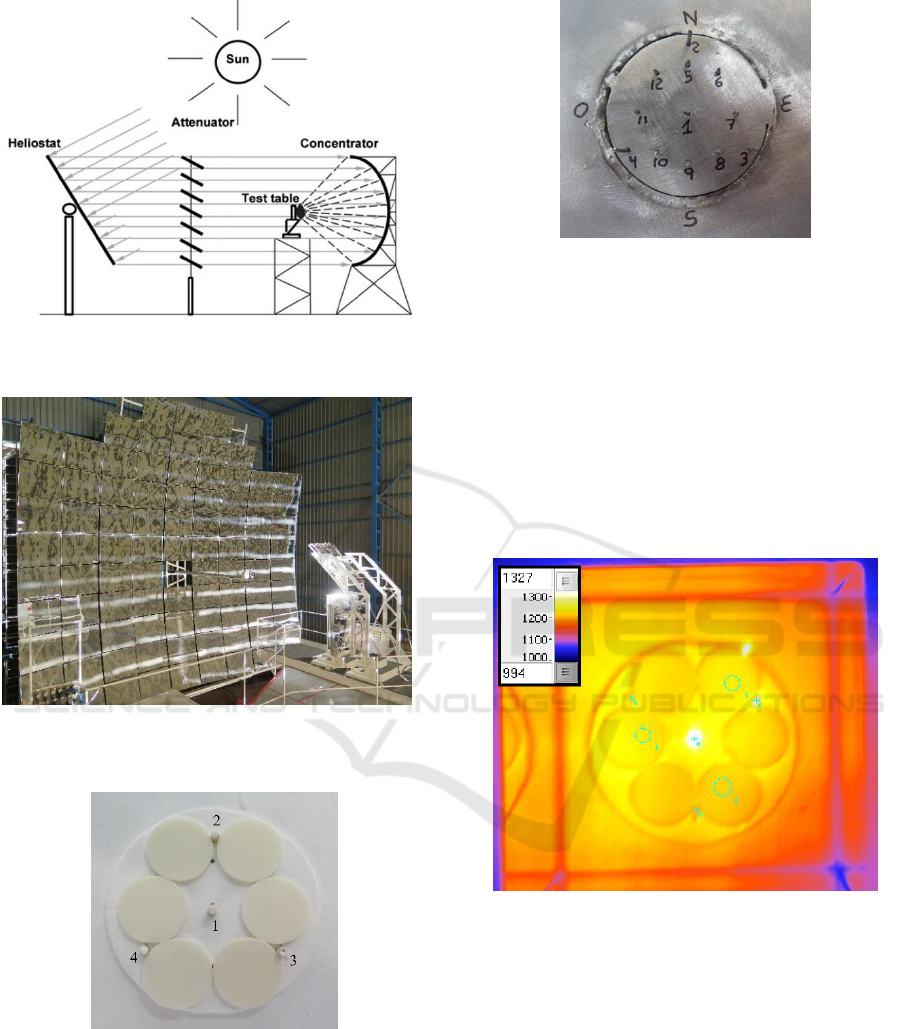
Figure 1: Schematics of SF60 test system at Plataforma
Solar de Almería (Martínez Plaza, 2013).
Figure 2: Parabolic concentrator, 45º inclined mirror and
the test table of SF60 solar furnace.
Figure 3: Discs of RAPAL
®
100 ready to be irradiated.
For measuring the temperature at various
locations in the vicinity of the discs, twelve type K
thermocouples were used. Figure 4 shows the
locations of the thermocouples’ joints, after removing
the discs, the zirconia felt, and the alumina
thermocouple protection sheaths.
Figure 4: Locations of the thermocouples’ joints.
For obtaining a more homogeneous distribution of
temperature at the surface of the discs, a device
(named “homogenizer”) composed of vertical mirrors
was placed close to the focal zone. The distribution of
temperature was also evaluated using an infra-red
camera and its software (see Figure 5); characteristics
of IR CAM model: Equus 327k SM PRO; detector:
Indium Antimonide (InSb) focal plane array (FPA);
resolution: 327 680 (640 512) pixels; spectral range:
1.5 μm to 5 μm (SM).
Figure 5: Image obtained by the IR CAM software.
To generate rapid heating-cooling cycles at the
surface of the irradiated discs, an automatic system
was developed composed by a plate with
reciprocating motion, i.e. with a repetitive back-and-
forth linear motion. This type of horizontal shutter is
placed close to the focal zone in order to interfere with
solar radiation flux before it irradiates the discs. The
cooling of the discs can be accelerated by blowing
them with compressed air.
Thermal Cycling Behaviour of Dense Monolithic Alumina
175
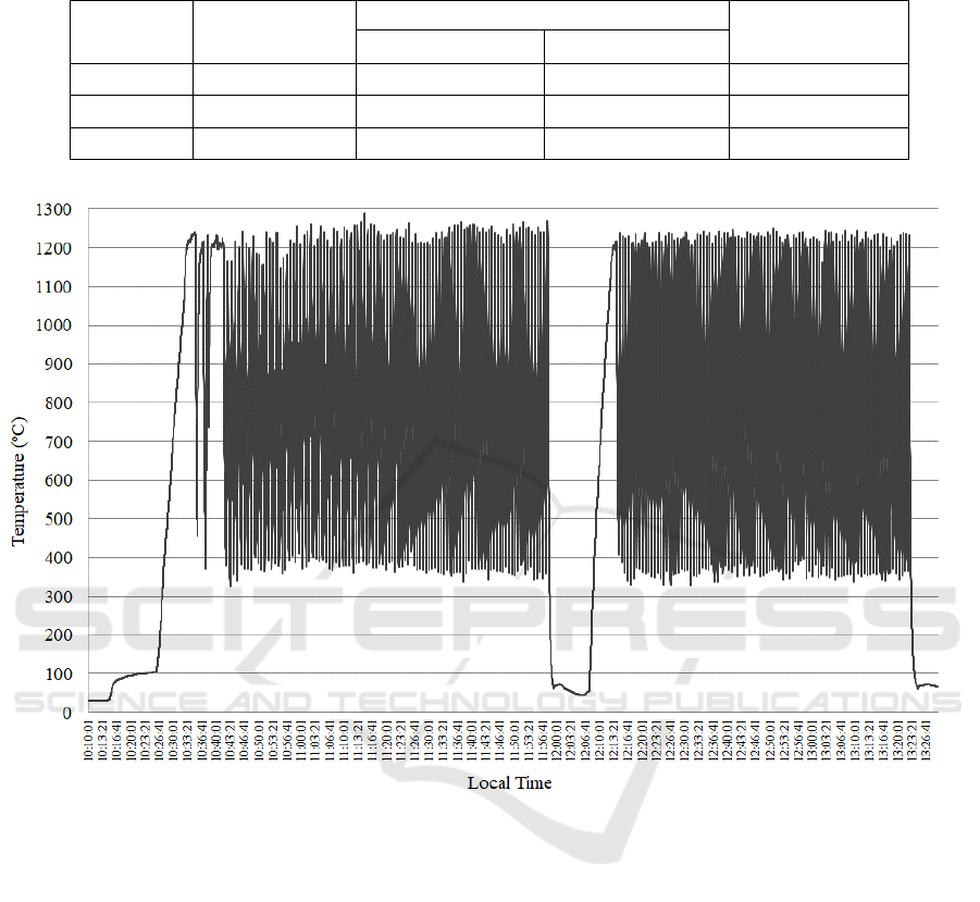
Table 1: Groups of discs and corresponding heating-cooling cycles.
No. of thermal
cycles
Temperature at central thermocouple
Total duration of 100
cycles
Maximum
Minimum
Group A
100
1200°C
900°C
≈ 35 minutes
Group B
100
1200°C
400°C
≈ 150 minutes
Group C
100
1200°C
400°C
≈ 77 minutes
Figure 6: Example of heating-cooling cycles.
All discs were exposed to 100 heating-cooling
cycles with the same maximum temperature, T
max
=
1200°C, measured by the thermocouple with the
reference number 1 (located at the centre). Table 1
summarizes the differences among the heat
treatments applied to the three groups of discs.
Beside these three groups (each one composed of
12 discs) that were exposed to the thermal cycling,
another group of 12 unexposed discs was used for
assessing the mechanical properties before the
thermal cycling.
An example of the heating-cooling cycles
obtained by exposure of the discs to concentrated
solar radiation is shown in Figure 6: the thermal
cycling of group C discs (T
max
≈ 1200°C; T
min
≈
400°C). In this case, 6 discs were exposed to 100
cycles between 10:36 and 11:56 (local time) and then
other 6 discs were exposed to 100 cycles between
12:13 and 13:23 (local time). In solar furnaces it is a
tradition to register the temperatures versus the local
time (hour of the day). We need the best insolation
conditions to attain high-temperature in the
experiments. In our experiments the solar radiation
reaching the heliostat was in range of 700 – 840 W/m
2
depending on the hour and weather conditions during
the day.
A close view of variation of temperature versus
time for two thermal cycles (in the period between
12:39:40 and 12:41:10 of Figure 6) is shown in Figure
7. The temperature indicated in both Figures 6 and 7
is the temperature measured by the thermocouple
located at the centre (i.e. the thermocouple with
reference no. 1 in Figure 4). Heating and cooling rates
must be determined from the experimental data. In the
MEEP 2018 - The Second International Conference on Materials Chemistry and Environmental Protection
176
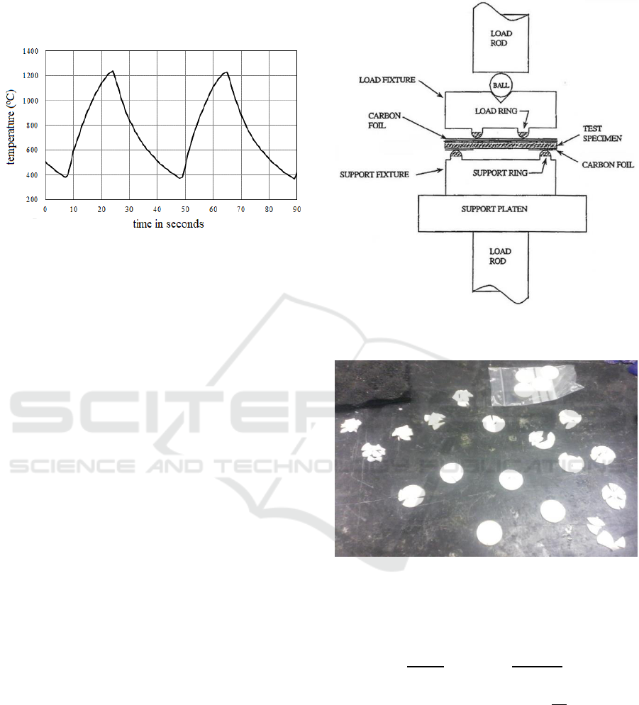
case of Figure 7, each period of heating from 400ºC
till 1200ºC takes circa 17 seconds; and the cooling
period from 1200ºC back to 400ºC takes around 24
seconds.
Figure 7: Temperature versus time for cycles in the period
between 12:39:40 and 12:41:10 of Figure 6.
2.3 Determination of E and G
Young’s modulus (E) and Coulomb’s modulus (G)
were determined by excitation of vibration in the
discs and measurements of resonant frequencies,
according to ASTM E 1876 standard test method. The
equipment used was made by IMCE n.v. – Integrated
Material Control Engineering (Diepenbeek,
Belgium). The procedure consists in tapping the
sample (disc) with a small hammer and recording the
induced vibration signal with a microphone.
Afterwards, the acquired vibration signal in the time
domain is converted to the frequency domain by a fast
Fourier transformation. Dedicated software
determines the resonant frequency for each type of
vibration: flexural or torsional, and then, using the
classical theory of elasticity, calculates E and G
values once the mass and the geometry of the test-
piece are known.
2.4 Equibiaxial Flexural Strength
Figure 8 provides a schematics showing the ring-on-
ring test set-up used for determination of monotonic
equibiaxial flexural strength at ambient temperature,
according to ASTM C 1499 standard test method. A
self-aligning ring-on-ring jig that generates the
equibiaxial flexure is placed between compression
plates in a universal mechanical testing machine
(Instron 5566 equipped with a 10 kN load cell). The
test-piece (alumina disc) is compressed between two
concentric rings with different diameter. In our
experiments, the crosshead velocity of the testing
machine was 0.5 mm per minute. Figure 9 depicts a
group of alumina discs after being fractured by the
ring-on-ring test procedure.
Figure 8: Section view of basic fixturing and test specimen
for equibiaxial testing according to ASTM C 1499.
Figure 9: A group of alumina discs after ring-on-ring tests.
The flexural strength
in equibiaxial conditions
is given by (Fernandes and Rosa, 1991):
(3)
where F refers to the rupture load, h the specimen
thickness,
the Poisson's ratio of the specimen
material,
the diameter of the lower ring (20.2mm),
the diameter of the upper ring (10.1 mm), and
the diameter of the test-piece (alumina disc).
Thermal Cycling Behaviour of Dense Monolithic Alumina
177
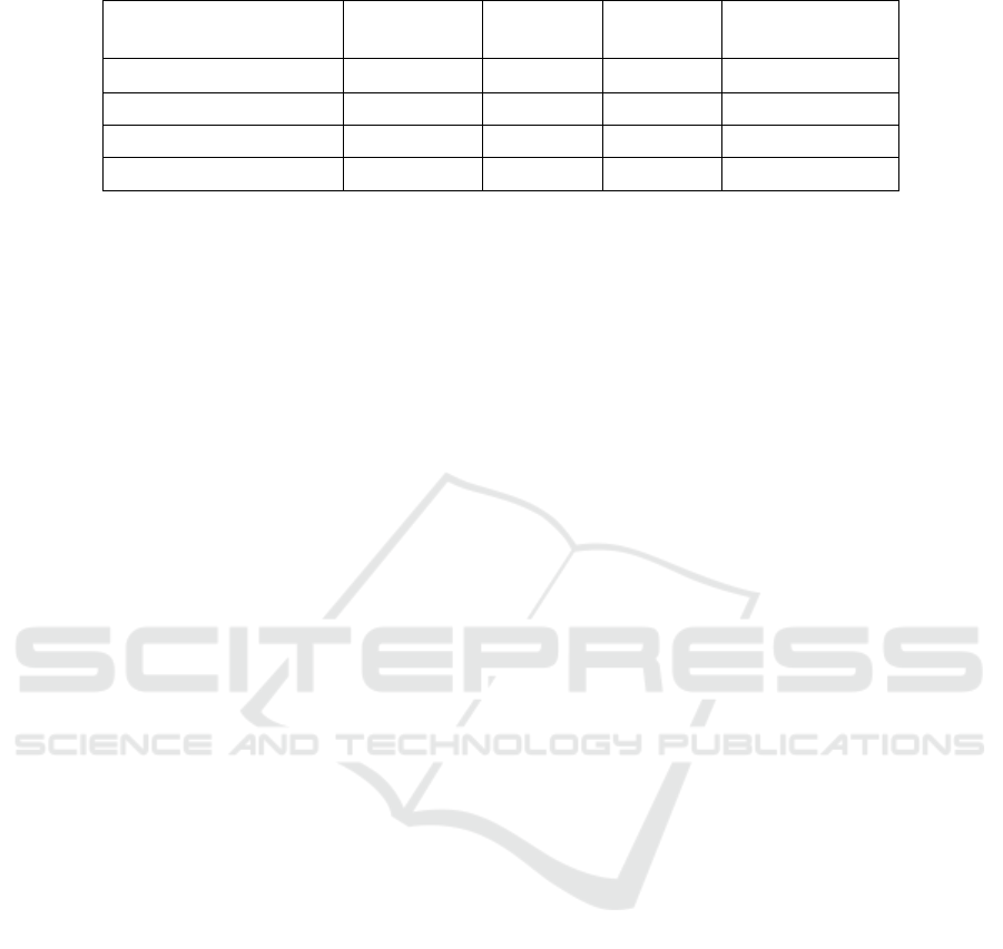
Table 2. Average values (± standard deviation) of properties before and after heating-cooling cycles.
Density
[g/cm
3
]
E
[GPa]
G
[GPa]
Flexural Strength
[MPa]
Before: reference group
3.91 ± 0.01
364 ± 7
158 ± 2
244 ± 46
After: Group A
3.93 ± 0.01
369 ± 8
159 ± 2
238 ± 37
After: Group B
3.92 ± 0.01
363 ± 7
157 ± 2
211 ± 34
After: Group C
3.92 ± 0.01
362 ± 6
158 ± 2
242 ± 31
3 RESULTS AND DISCUSSION
The results obtained from the experiments allow to
compare the values of the properties before and after
exposure to thermal cycling. This was the rationale
used to evaluate the possible degradation of the
alumina when exposed to rapid thermal cycles at
high-temperature. Table 2 summarizes the average (±
standard deviation) values obtained for the following
properties of RAPAL
®
100: density (determined by
Archimedes method); Young’s modulus of elasticity
(E); Coulomb’s modulus of elasticity (G); and
equibiaxial flexural strength.
In the whole literature, we did not find other
researchers’ results for comparison, because the
thermal cycling experiments described in this work
are very difficult to be performed with conventional
furnaces; and therefore the results obtained in the
present work are relevant. They have demonstrated
the good quality of RAPAL
®
100 and its adequacy for
high temperature applications. We have not observed
any rupture in the alumina discs during their exposure
to the thermal cycles. None of the different sequences
of 100 cycles (even the most severe one with 100
cycles applied in 77 minutes, with maximum
temperature of 1200°C and minimum temperature of
400°C) has caused noticeable alterations in the
studied properties (density; Young´s modulus of
elasticity; Coulomb´s modulus of elasticity; flexural
strength) when comparing the values before and after
applying the heating-cooling cycles. The only
perceptible difference it is practically negligible; it
consists in the decay of flexural strength after
exposure to 100 cycles in 150 minutes, with T
max
=
1200°C e T
min
= 400°C; initial value is 244 (±46) MPa
and after those 100 cycles is 211 (±34) MPa.
According to the work of (Hahn and Lee,1999)
the critical thermal stress which makes the cracks
grow catastrophically was found to be generated by
the critical cooling rate, and the critical cooling rate
of polycrystalline alumina ceramics was found to be
a certain value: 550ºC/second (Hahn and Lee, 1999).
In our experiments the highest cooling rate was
approximately 34ºC/s which is circa 16 times less
than 550ºC/s. This explains why we did not notice
any crack propagation in the test-pieces, even after
100 cycles; as well as we did not obtain any relevant
statistical changes in the mechanical properties.
The value of Young’s modulus mentioned in the
Rauschert data sheet (see section 2.1) is 380 GPa,
slightly higher than the value obtained in our work,
364 (±7) GPa, for the reference group of “as received”
samples i.e. before exposure to thermal cycling (see
Table 2). This small discrepancy can be explained by
differences in the testing methods. Also, Rauschert
data sheet mentions that uniaxial flexural strength of
RAPAL
®
100 is 300 MPa, without referring the data
scatter. In our work we measured the flexural strength
under equibiaxial conditions and obtained a lower
average value, 244 (±46) MPa, for the reference
group i.e. before the heating-cooling cycles. These
values are perfectly acceptable because the uniaxial
flexural strength is typically determined under a 3-
point bend test (where the sampled volume is
smaller), so the probability of finding a larger critical
flaw is higher in equibiaxial conditions, resulting in a
lower flexural strength.
4 CONCLUSIONS
This work demonstrates that rapid variations of
temperature at the surface of a material can be
attained by direct exposure to highly concentrated
solar radiation. For the first time, the thermal cycling
behaviour of dense monolithic alumina (RAPAL®
100) was studied, using rapid heating-cooling cycles
with a maximum temperature of 1200ºC. The results
prove the adequacy of this material for high
temperature applications subjected to rapidly
changing thermal conditions.
MEEP 2018 - The Second International Conference on Materials Chemistry and Environmental Protection
178

ACKNOWLEDGEMENTS
This research has been partially funded by the
European Commission in the frame of the SFERA-II
project (FP7, Grant. Agreement 312643) and project
INSHIP (Integrating National Research Agendas on
Solar Heat for Industrial Processes) www.inship.eu.
REFERENCES
Belghalem, H., Hamidouche, M., Gremillard, L.,
Bonnefont, G., Fantozzi, G., 2014. Thermal shock
resistance of two micro-structured alumina obtained by
natural sintering and SPS. Ceram. Int. 40, 619–627.
Dimitrijevic, M.M., Medjo, B., Heinemann, R.J., Rakin,
M., Volkov-Husovic, T., 2013. Experimental and
numerical analysis of thermal shock damages to
alumina based ceramic disk samples. Mater. Des. 50,
1011–1018.
Douale, P., Serror, S., Duval, R.M.P., Serra, J.J., Felder, E.,
1999. Thermal shocks on an electrolytic chromium
coating in a solar furnace. Journal de Physique IV 9,
429–434.
Evans, A.G., Linzer, M., Johnson, H., Hasselman, D.P.H.,
Kipp, M.E., 1975. Thermal fracture studies in ceramic
systems using an acoustic emission technique. J. Mater.
Sci. 10, 1608–1615.
Fernandes, J.J., Rosa, L.G., 1991. Ensaios biaxiais de
cerâmicos. Actas V Encontro Nacional da Sociedade
Portuguesa de Materiais, Lisboa, Vol.1, pp 375–384,
doi: 10.13140/RG.2.1.2589.6809.
Hahn, B.S., Lee, H.L., 1999. Effect of environmental
factors on thermal shock behaviour of polycrystalline
alumina ceramics. J. Mater. Sci. 34, 3623-3630.
Hirata, Y., 2015. Theoretical analyses of thermal shock and
thermal expansion coefficients of metals and ceramics.
Ceram. Int. 41, 1145–1153.
Kováčik, J., Emmer, S., Rodriguez, J., Cañadas I., 2014.
Solar furnace: thermal shock behaviour of TiB2 coating
on steel. Proceedings of METAL 2014, pp 863–868.
Tanger Ltd, Ostrava, Czech Republic.
Lee, J.H., Park, S.E., Lee, H.J., Lee, H.L., 2002. Thermal
shock behaviour of alumina ceramics by ball-on-3-ball
test. Mater. Lett. 56, 1022–1029.
Li, D.Y., Li, W.G., Wang, R.Z., Kou, H.B., 2016. Influence
of thermal shock damage on the flexure strength of
alumina ceramic at different temperatures. Mater. Lett.
173, 91–94.
Martínez Plaza, D., 2013. Desarollo de dispositivo para
producción de energía térmica a partir de un receptor
solar de tipo volumétrico y estudio de su aplicabilidad
a procesos de alta temperatura para fabricación
industrial de cerámicas, PhD thesis, Universidad de
Sevilla.
Rauschert data sheet, 2018. Available at:
https://rauschert.com/images/documents/products/tech
nical-ceramics/Rapal_Tabelle.pdf
Saâdaoui, M., Fantozzi, G., 1998. Crack growth resistance
under thermal shock loading of alumina. Mater. Sci.
Eng. A247, 142–151.
Sallaberry, F., García de Jalón, A., Zaversky, F., Vázquez,
A.J., López-Delgado A., Tamayo, A., Mazo, M.A.,
2015. Towards standard testing materials for high
temperature solar receivers. Energy Procedia 69, 532–
542.
Thermal Cycling Behaviour of Dense Monolithic Alumina
179
