
Directivity of Transducer Array
Guozhu Zhao
Civil Aviation Flight University of China Guanghan Sichuan, China
Keywords: Acoustic directivity; Transducer; Sound radiating; Transducer array; Resonance frequencies.
Abstract: According to the research of acoustic directivity by using MATLAB software, selection of a relatively
larger surface of the transducer and a relatively closer transducer interval will be more preferable for
directivity. On the other hand, when the structure of the sound radiating surface of the transducer or array
layout is symmetrical, the corresponding directivity pattern will be symmetrical. The two resonance
frequencies of a single transducer and a transducer array are measured by an impedance analyzer. And
according to the resonant frequency 23kHz, high-power directivity acoustic transducer hardware experiment
platform is designed. And this design, which can successfully drive sound transducer array and the drive
power is about 10w, can ensure that the ultrasonic signal’s amplification will be performed without
distortion, while the magnification can reach to 20 times. In order to test transducer’ directivity, two
methods are designed.
1 INTRODUCTION
By analyzing the electrical characteristics of
piezoelectric transducer, it could offer to help for the
design of the directional acoustic transducer circuit
platform. Directional acoustic transducer system’s
basic purpose is an audio input signal, using
program to process signal, then power amplification,
and ultrasonic signals that contain the audio signal
are sent into the air, finally, the audio signal is
released from the ultrasonic in the air, which realizes
its high directional transmission[1]. Because this
paper does not involve relevant signal processing,
designing hardware circuit platform can provide a
solid foundation for the later work of the research.
However, the premise is to make sure that the circuit
designed could work properly, and the signals of the
ultrasound are amplified, essentially without
distortion [2, 3, 4].
The section of signal processing is not
considered for the moment, and we only consider
hardware platform where the transducer emit a
directional sound. The following design scheme is
adapted, The entire hardware component of the
audio directional system[5-6].Among them, the
transducer array design and impedance matching
circuit design has been completed, the next thing to
do is to power amplifier, power source and the
design of filter circuit, its difficulty is class D power
amplifier design[7, 8].
The total design scheme of electrical circuit. The
section of signal processing is not considered for the
moment, and we only consider hardware platform
where the transducer emit a directional sound. The
following design scheme is adapted, Figure 39 is a
total design scheme of the audio directional system
signal processing platform. The entire hardware
component of the audio directional system is:
(1) power supply module, it provides positive
and negative power supplied for power amplifier.
(2)the signal source, it produces high frequency
signals, will only provide more than 20kHz of
ultrasonic signals, due to the absence of signal
processing.
(3)Power amplifier, it can achieve high
efficiency of ultrasonic signal, with amplification of
low distortion rate.
(4)Filter circuit, it selects the appropriate circuit
or component to filter the output of the power
amplifier.
(5)Designing transducer array.
(6)Designing impedance matching circuit.
Among them, the transducer array design and
impedance matching circuit design has been
completed, the next thing to do is to power

amplifier, power source and the design of filter
circuit, its difficulty is class D power amplifier
design.
2 CLASS D POWER AMPLIFIER
To design the power amplifier to enlarge the signal
after power transducer, producing mechanical
vibration, to the side of launch ultrasonic wave in
the air, the power amplifier is to prepare the way for
signal processing, therefore it requires small signal
distortion rate, higher efficiency magnification at
about 20 times. Class C power amplifier, also known
as the class B amplifier, is a powerful amplifier with
a high distortion rate, and the advantage of C is that
the output is high. But due to serious distortion of
the characteristics of this kind of power amplifier is
not suitable for the Hi-Fi applicable to enlarge, of
course, and is not applicable to complex sound
signal processing, and is not suitable for directional
acoustic signal processing. Class D power
amplifiers, also called power amplifiers, are known
as digital power amplifiers. Transistor of circuit,
once the open directly to the load connected with the
power supply, current flows through a transistor, but
no voltage in the transistor and voltage load directly
to the load, Thus the power consumption is small so
that it can achieve the purpose of improving
efficiency. When the output transistor is closed, all
the power supply voltage on the transistor, and the
transistor without conduction, there would be no
current, also not consumed power, so the efficiency
of the power amplifier in theory should be 100%.
As shown in figure1 and 2, the advantages of
class D power amplifier are high efficiency. The
power module is generally integrated into the chip,
and it is difficult to design alone. The performance
of this type is stable and the size is small, producing
less heat. Because of this, without large radiator, the
fuselage can significantly reduce the volume and
weight, and due to the absence of the distortion, the
theoretical distortion is low and the linear effect is
better, But the power amplifier is complex, the
circuit design is more complex, so the truly
successful product is less and the market price is not
cheap. Because of the above situation, the class D
power amplifier is specially designed, which is used
to solve the problems related to the research of high-
power directional acoustic transducer.
The D class amplification is called the class D
power amplifier, which is 100 percent efficient
because the power amplifier controls MOSFET
output power. The class D power amplifier design
needs to consider the main problem, including:
modulation method, the design of the low-pass LC
filter, the selection of the output power MOSFET
switch tube, the protection of the output stage, etc.
Choosing a kind of drive circuit with the
protective type PWM power amplifier, the circuit is
used for under 55 kHz ultrasonic power amplifier.
When the supply voltage is±12 v, the expected
voltage amplification can reach more than 20 times,
and the output power is not less than 10W. The
signal, after power amplification, constitute a low-
pass filter circuit by L1 and C12, which Filter out
the unneeded high-frequency signals, and the rest of
the ultrasonic signal is the signal for the output of
the output-end. When a given frequency is 24kHz,
we can obtain the corresponding power amplifier
output and input waveform. the magnification of the
power amplifier that be found is 20 times. in
promoting the nine transducer array when there is no
obvious distortion of power amplifier input signal of
1.5 V in input end, and the output voltage is 30 V.
In this project, it is necessary to design the DC
power supply, because the power source required by
above class D power amplifier is dual power supply.
The 220 v alternating current through the
transformer T1 output low voltage alternating
current. Then, after four diode rectification, you take
the zero point in the middle of the transformer T1,
and the zero point is exactly the middle of the
transformer. The output voltage is -12 V and 12V,
and pressure drop is 24V on both ends of the output
of power source , and the output current is greater
than 500mA. These parameters can satisfy the driver
requirements of the class D power amplifier. In
subsequent chapters, we will focus on the
directionality measurement of the directional
acoustic transducer array.
Figure 1. Circuit diagram of class D power amplifier.
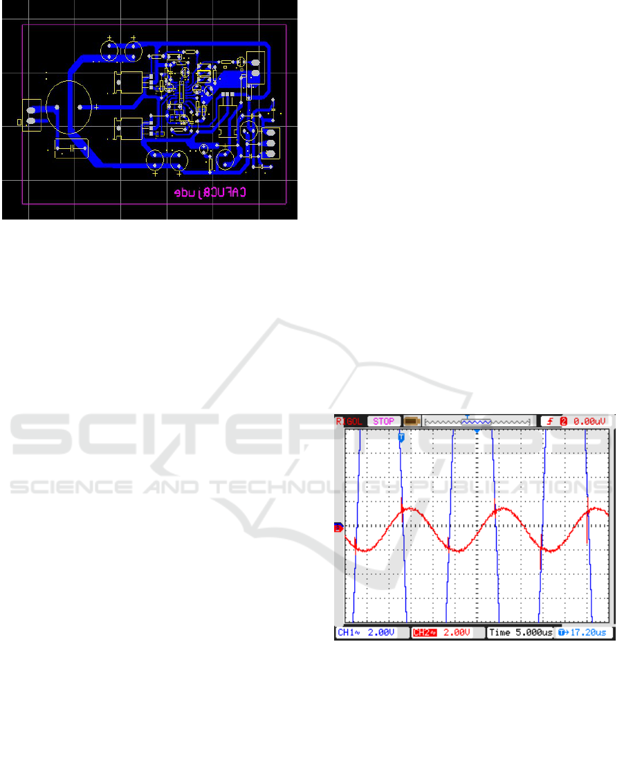
Figure 2. Class D power amplifier PCB diagram.
Class D power amplifier design needs to
consider the main problem is: modulation method,
the selection of the output power switch tube, the
output level of protection, LC low-pass filter design
and EMI treatment etc. Choosing a kind of power
amplifier drive circuit with protective type PWM, It
must satisfy four functions of the class D power
amplifier, including: PWM modulation, built-in
level conversion, grid drive of MOS tube and
overcharge protection. In order to use the minimum
of peripheral components to design, it adopts chip
IRS2092S to produce the vibration mode pulse
width modulation, the chip can support the amplifier
under 55 KHZ frequency, and the chip can cooperate
with a half-bridge power amplification circuit,
composed of two MOSFET work. The circuit is used
for power amplifier of ultrasonic signal under 55
kHz and audio wave signal. when the supply voltage
is 12 v, it is expected to reach 20 times, and Its
output power is not less than 10W for the class D
power amplifier PCB and class D.
3 FILTER CIRCUIT
The power amplifying signal goes through the low
pass filter circuit of L1 and C12 in figure 3, which is
connected to the output of the D-type power
amplifier. The unneeded signals are filtered out by
the filtered circuit, and the rest of the signal is the
output of an ultrasonic signal.
When a given frequency is 24 KHZ, the
corresponding power amplifier output and input
waveform as shown in figure 3, which peaks higher
waveform presents output waveform, and wave
lower input waveform indicates input waveform.
There was no apparent distortion in the array of nine
transducers, and when the input of the power
amplifier input is 1.5V, the voltage of the amplifier
is 30V, and we can find that the amplification of the
amplifier is 20 times. This voltage is the maximum
voltage that a transducer can withstand. You can see
from the diagram that the blue waveform diagram
representing the output is not distorted. That is to
say, the design of class D power amplifier can
achieve the desired purpose, can amplify the
ultrasonic signals, and working condition of LC
filter circuit is good, basically can achieve output
without distortion, whose magnification can be up to
20 times, and whose frequency response in the range
of 20HZ-55kHZ. Although there is no signal
processing, but from the perspective of signal
processing, it is not theoretically distorted by the
class D power amplifier, when the signal is
transmitted on a carrier with a high frequency signal
of 24kHz. For the class D power amplifier designed,
the DC power supply that is designed and matched is
necessary. Because the class D power amplifier chip
drives the MOSFET, The type of power device is
used only in N channel, and there is no circuit design
of N channel and P channel. To this end, the voltage
is high, and the design of the dual power supply can
meet this requirement, which designs the power
supply as shown below.
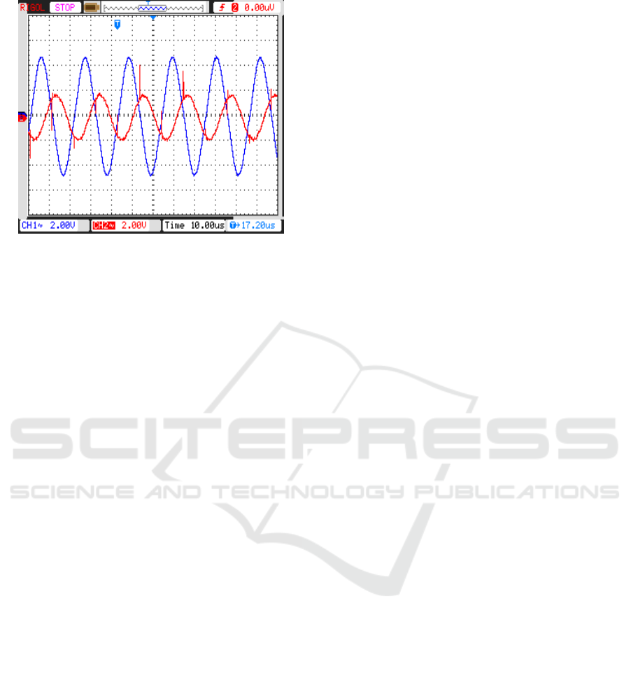
Figure 3 comparison of input and output signals of class D
amplifier.
4 POWER MODULE DESIGN
The basic principle of the power supply is that 220 v
alternating current through the transformer T1
output low voltage alternating current. Then, after
four diode rectification, you take the zero point in
the middle of the transformer T1, and the zero point
is exactly the middle of the transformer. Finally,
pressure drop is 24V on both ends of the output of
power source, and the output voltage is -12 V and
12V, and the output current is greater than 500mA,
and the output power is not less than 10W. These
parameters can satisfy the driver requirements of the
class D power amplifier. The D class amplification
is called the class D power amplifier, which is 100
percent efficient because the power amplifier
controls MOSFET output power. The class D power
amplifier design needs to consider the main
problem, including: modulation method, the design
of the low-pass LC filter, the selection of the output
power MOSFET switch tube, the protection of the
output stage, etc.
Choosing a kind of drive circuit with the
protective type PWM power amplifier, the circuit is
used for under55kHz ultrasonic power amplifier.
When the supply voltage is±12v, the expected
voltage amplification can reach more than 20 times,
and the output power is not less than 10W. The
signal, after power amplification, constitute a low-
pass filter circuit by L1 and C12, which Filter out
the unneeded high-frequency signals, and the rest of
the ultrasonic signal is the signal for the output of
the output-end. When a given frequency is 24kHz,
we can obtain the corresponding power amplifier
output and input waveform. the magnification of the
power amplifier that be found is 20 times. in
promoting the nine transducer array when there is no
obvious distortion of power amplifier input signal of
1.5 V in input end, and the output voltage is 30 V.
5 CONCLUSIONS
In this project, it is necessary to design the DC
power supply, because the power source required by
above class D power amplifier is dual power supply.
The 220 v alternating current through the
transformer T1 output low voltage alternating
current. Then, after four diode rectification, you take
the zero point in the middle of the transformer T1,
and the zero point is exactly the middle of the
transformer. The output voltage is -12 V and 12V,
and pressure drop is 24V on both ends of the output
of power source , and the output current is greater
than 500mA. These parameters can satisfy the driver
requirements of the class D power amplifier. In
subsequent chapters, we will focus on the
directionality measurement of the directional
acoustic transducer array. By analyzing the electrical
characteristics of piezoelectric transducer, it could
offer to help for the design of the directional
acoustic transducer circuit platform. Directional
acoustic transducer system’s basic purpose is an
audio input signal, using program to process signal,
then power amplification, and ultrasonic signals that
contain the audio signal are sent into the air, finally,
the audio signal is released from the ultrasonic in the
air, which realizes its high directional transmission.
Because this paper does not involve relevant signal
processing, designing hardware circuit platform can
provide a solid foundation for the later work of the
research. However, the premise is to make sure that
the circuit designed could work properly, and the
signals of the ultrasound are amplified, essentially
without distortion.
ACKNOWLEDGEMENT
This work was financially supported by fund project
of Civil Aviation Flight University of China
(Q2018-170) and (J2015-63). Helicopter multi
mission flight training device development, civil
aviation innovation and guidance fund projects
major projects ( MHRD20130108 ).

REFERENCES
1. Chen Min. Research on the Fundamental Theory and
Key Technologies of Audio Directional System [PhD].
University of Electronic Science and Technology of
China, (2008).
2. Masashi Yamada, Nobuyuki Itsuki, Yohsuke
Kinouchi. Adaptive Directivity Control of Speaker
Array[J]. Proceedings of the 8th International
Conference on Control, Automation, Robotics and
Vision, Kunming, China, Dec 6-9, (2004).
3. M. Yoneyama, J.-I. Fujimoto. The Audio Spotlight: An
Application of Nonlinear Interaction of Sound Waves
to a New Type of Loudspeaker Design[J]. The Journal
of the Acoustical Society of America, (1983).
4. Woon-Seng Gan, Jun Yang, Khim-Sia Tan, et al. A
Digital Beamsteerer for Difference Frequency in a
Parametric Array[J]. IEEE Transactions on Audio,
Speech and Language Processing(2006).
5. T. Kamakura, T. Yoneyama and K. Ikegaya. Studies
for the Realization of Parametric Loudspeaker[J].
Journal of Acoustic Society of Japan(1985).
6. T. Kamakura, M. Yoneyama, K. Ikegaya.
Developments of Parametric Loudspeaker for Practical
Use[J]. 10th International Symposium on Nonlinear
Acoustics, Kobe, Japan(1984).
7. F. J. Pompei. The Use of Airborne Ultrasonics for
Generating Audible Sound Beams[J]. Journal of Audio
Engineering Society(1999).
8. J. James, J. O. Norris. HSS white paper[M]. USA:
American Technology Corporation(2005).
