
Research on the NC Maching ToolpathTtrategy of Complex Curve
Surface
Zhu ming Cao
1
, Lu Lu
1
,Kun Qiu
1
,Dongying Zhang
1
and Jiatian Guo
2
1.
School of Mechanical Engineering,Beijing Polytechnic,Beijing 100176
,
China
;
2
.Department of Automotive Engineering
,
Shandong Vocational College of science and technology,Shandong Weifang
261053
,
China
Keywords: Complex curve surface; NC machining; Tool path; Cutter axis vector; optimize.
Abstract: With the progress of science and technology and the personalized needs of users, complex curve surface has
been widely used in aerospace, ship, vehicle, molds, medical devices and other industries. Efficient and
precise manufacturing of complex curve surfaces is an important research direction of the advanced
manufacturing technology. This paper research the NC machining tool path for a complex curve surface,
and for the feature of the surface to choose the variable contour milling strategy. Optimization of the cutter
axis vector, achieve the projection from cutting point of the cutter to the cutter axis is the largest when
cutting the surface. So as to achieve the maximum cutting speed and improve the surface quality. This paper
constructs the change model of the cutter axis vector of the cutting process, and the optimization of the
rotation angle of the cutter axis vector is completed. The design and precision requirements, high surface
quality and precision can be obtained by using this strategy and model.
1 INTRODUCTION
With the progress of the personalized needs of
users, complex curve surface has been widely
used in aerospace, ship, vehicle, molds, medical
devices and other industries. Common products
include impeller blades for aero engines,
propellers in ships, turbines for vehicle engines,
etc. The machining of these surfaces requires a
complex cutting motion between the cutter and
the workpiece on the multi-axis NC machine tool.
The NC machining technology determines the
machining accuracy and the machining efficiency
of these complex curve surface parts, thus
affecting their performance. The key and
difficulty of complex curve surface machining is
the process of computer aided manufacturing.
Professional, efficient, safe and intelligent CAM
software must be used. And the processing
technology, precision and efficiency can be
embodied in the tool path through computer
assistance. Therefore, the research on the
machining technology of complex curve surface is
focus on the research of the path of the machining
tool, and the tool path planning has a direct
impact on the machining efficiency and precision
of the parts.
As shown in Fig 1-a,the mainly work of the
tool path planning of the complex curve surface is
determination of the completion of the cutter site
and the cutter axis vector. Cutting position is
selected by a driver, and based on the determined
projection vector, the cutter location point is
created by making the driving point generated on
the drive to project onto the component geometry
by the specified projection vector. As shown in
Fig 1-b.The tool axis vector setting refers to the
tool axis pointing in the machining process to
move according to certain strategies. Commonly
used strategies of the knife shaft include away
from point, orient to point, away from straight line,
orient the straight line, perpendicular to the driver,
relative to the driver, interpolation vectors, four
axis perpendicular to the driver and four axis
relatives to the driver body, etc. When machining
complex curve surfaces, it is usually necessary to
have multiple cutting tools to complete. In theory,
only pass the three steps of cutting point
positioning, cutting tool path planning and
collision inspection, then be sure non-interference
tool path, it can be done. The main process of tool
path generation is: ① determine the tool
positioning strategy, realized the maximization of
machining line width without over-cutting; ②
determine the method to generate the knife path,
calculate row spacing, walking distance, cutting
depth and other parameters, to minimize the total
length of tool path in the premise of ensuring the
continuity and smoothness of the knife road; ③
avoid the interference of tools with workpieces
and fixtures with workbenches. These three
aspects are mutually complementary and closely
related. In the actual processing, we should
consider the tool positioning, the axial vector light,
the shape of the knife, the length of the tool, the
machining parameters, the interference and the
characteristics of the machine movement, etc. It is
the difficulty of complex curve surface machining.
Therefore, most research on tool path planning is
limited in several aspects. In this paper, we
research the cutter axis strategy of "four-axis
relative to drive". This strategy is used to
construct the change model of the cutter axis,
optimize the relevant parameters, and complete
the efficient and precise manufacturing of a
complex curve surface.
(a)The principle of cutter location algorithm
(b)cutter location point generation principle
Fig1 generating tool path of the complex curve surface.
2 RESEARCH ON THE STRATEGY
OF "4-AXIS RELATIVE TO THE
DRIVER"
The "4-axis relative to the driver" is a commonly
used tool path strategy in the four-axis CNC
machining process, and it is widely used in the
manufacture of mould, blade and aviation parts.
This cutter axis strategy adds a "front rake Angle"
and an "side inclination Angle" based on the "4-
axis perpendicular to the component" tool axis
strategy to make the cutter shaft more flexible and
reliable, as shown in Fig2.The cutter axis strategy
requires the cutter axis to be perpendicular to the
driver or machining surface, and the plane
projection which is perpendicular to the axis
rotation Angle X. Then it can set the front rake
Angle, side inclination Angle and rotation Angle
to adjust the direction of the axis vector to meet
the processing demand of various curved surfaces.
The operation mode of the 4-axis relative to the
driver is: Select 4- axis relative to the driver as the
cutter axis strategy; then define the connection of
two points as the axis of rotation; at last input the
desired 4 axis rotation Angle, front rake Angle and
side inclination Angle.
Fig2 the strategy of "4-axis relative to the driver".
As shown in Fig2,the main parameters of the
strategy of 4-axis relative to the driver include
rotation axis vector, front rake Angle, side
inclination Angle and rotation Angle. The rotation
axis vector refers to the vector direction of the
rotation axis in the parts during the four-axis
machining process; The front rake refers to the
cutter axis tilted toward the direction of the cutter,
it is affected by the direction of the tool
movement. The forward refers to the slope along
the direction of the tool path-Pull the walk, the
reverse refers to the reverse direction of the tool
path- push the walk, it is based on the vertical face
of the walking knife. The rotary surface of the
cutter is perpendicular to the direction of the
cutter when the cutter side inclination. Looking
back the first cutter feed direction, counter
clockwise is positive, clockwise is negative, it is
based on the direction of the walking cutter to
calculate the Angle. The rotation Angle makes all
the axes revolve around the defined rotation axis,
at the same time, keep the tool perpendicular to
the rotation axis. Looking from the direction of
the positive side of the rotation axis to the
negative, counter clockwise is positive, clockwise
is negative. Unlike the "front rake Angle", the
four-axis rotation Angle is always tilted to the
same side of the normal axis, which has nothing
to do with the direction of the cutter movement.
As shown in Fig3-b,When the direction of the
cutter is perpendicular to the rotation axis X, the
cutter axis can only be set forward and rotated,
and the setting side inclination is invalid. In order
to avoid the swing of the cutter axis too often, the
"one-way" strategy is set in the drive. As shown in
Fig3-c,When the direction of the cutter is parallel
to the axis of rotation, the axis of the cutter can
only set the side inclination Angle and rotation
Angle, and the front inclination is invalid, and the
effect of setting the side inclination Angle and
rotation Angle is the same, and the lateral
inclination cannot be greater than 90, otherwise
the cutter path is invalid. From the positive side of
the rotation Angle vector looks forward to
negative direction, counter clock wise is positive,
clockwise is negative. The rotation Angle vector
is calculated by the angular reference based on the
rotation vector.
(a) front rake and (b) perpendicular to the
side inclination rotationaxis
(c)parallel to the (d) rotationaxis
side inclinationrotationaxis rotationaxis
Fig3 cutter axis vector parameters.
3 APPLICATION RESEARCH ON 4-
AXIS RELATIVE TO THE
DRIVER
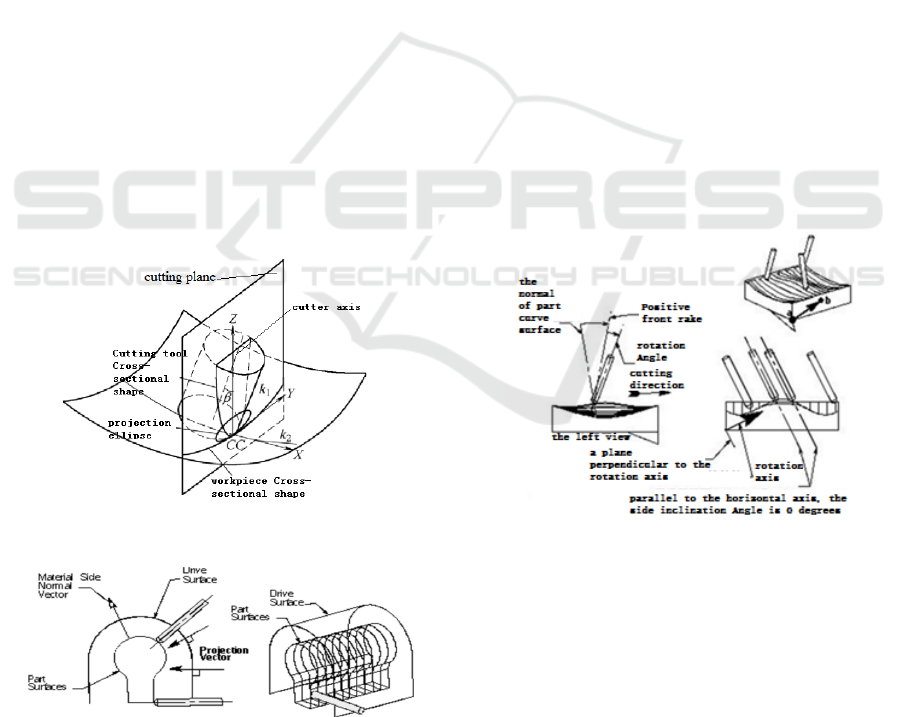
As shown in Fig4-a, the specimen in this paper is
a curved camshaft. The side curve surface of the
part and the hub need to use the four-axis NC
machining. The planning of tool path is required
before processing, including the setting of cutter
site and cutter axis vector. The tool path of the
lateral surface adopts the variable contour milling
strategy of UG10.0, machined surface selects the
processed surface; the projection vector is
perpendicular to the driver, the cutting mode is
reciprocating, the tolerance is set to 0.01,the cutter
point will be generated in the normal direction of
each point of the surface, as shown in Fig4-b;the
cutter axis is selected on the 4 axis relative to the
driver, when all the parameters are set to
0,generated the cutter axis as shown in Fig4-c,it
can be found that the cutter axis interferes with
the hub of the camshaft, therefore, the tool path
should be optimized.
(a)the surface of the driver
(b)the cutter point cloud
(c)cutter axis vector
Fig4 design the tool path for the curve surface of cam.
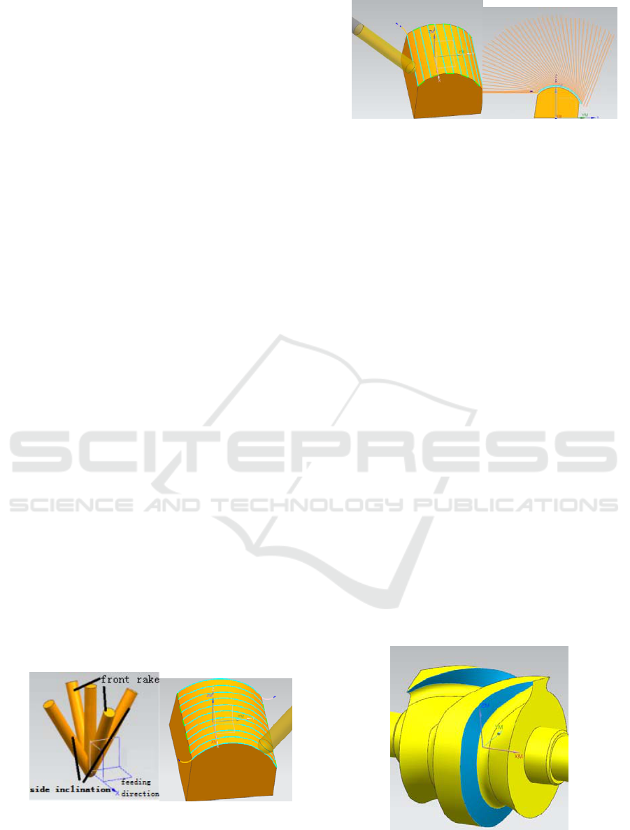
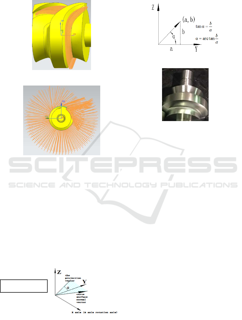
Because the rotation axis A of the component
is rotated around the X-axis, the cutter axis can
only rotate around the X-axis, so the rotation
Angle α of the cutter axis is the Angle that is
perpendicular to the driver at the cutter point, and
projection on the YZ plane, the Angle formed
with the Y-axis, as shown in Fig5-a.The cutter
axis can be interfered when the cutter axis
parameter is not set. Therefore, it is necessary to
optimize the cutter axis vector. This paper
research the tool path of the side curve surface of
the part, and design the maximum cutting speed to
be achieved without interference.
(a)cutter axis vector
(b)test pieces
Fig5 4 axes relative to the driver.
4 AXIS VECTOR OPTIMIZATIONS
To ensure the smoothness of the curved surface,
according to the cutting speed V=ωR1(R1 is the
vertical distance from the spher mill cutting point
to the cutter shaft),it should be ensured that R1
is the largest during processing, this will achieve
maximum cutting speed. Suppose the space plane
is a X+bY+cZ+D=0, the normal vector is(A,B,C),
so the space line can be represented as two planes
simultaneous. The result of the simultaneous
expression can be expressed θas the determinant,
as shown in formula 1;according to the spatial
linear two points, as shown in formula 2;the
normal vector of each point after cutting
is
f
a
=(
fff
zyx ,,
),The tool vertical it; the
normal vector for each point before cutting is
0
a
=(
000
,, zyx
); therefore, the change of the
normal vector per cutting
is(
000
,, zyx
)......(
nnn
zyx ,,
); if once reciprocate
can complete processing, then the Angle formula
cuttr poin
t

of
f
a
=(
fff
zyx ,,
) and
0
a
=(
000
,, zyx
) is as
shown in formula 3, the fastest cutting speed V
can be calculated by formula 4, 5 and 6.
According to the algorithm, use the software
verify that the θ value can be 63.476 ° --
78.889°.In this case, the rotation Angle θ is
selected as 70°, the higher surface quality can be
obtained through trial production, as shown in
Fig5-3
c
zz
b
yy
a
xx
000
( a 、 b 、 c is the
direction of the vector)①
2
1
2
1
2
1
zz
zz
yy
yy
xx
xx
(a、b、c is the
direction of the vector) ②
0
0
.
.
θcos
aa
aa
f
f
(
f
a
0
a
is unit vector)③
0000000
),,).(,,(.θcos zzyyxxzyxzyxaa
fffffff
④
)arccos(θ
000
zzyyxx
fff
(R is radius of spher mill for machining)⑤
2
000
2
1
)(-1R.θcos-1R.θsin.R zzyyxxR
fff
⑥
5 CONCLUSIONS
This paper research the cutter axis vector in the
machining process of camshaft side wall curve
surface. The tool path strategy of the curved
surface adopts the variable contour milling of
UG12.0;to maximize processing speed, the
direction of cutter axis vector is optimized, and
ensure that the cutting tool's cutting position is as
large as the vertical distance from the cutter shaft.
In this paper, the change process model of the
cutter axis vector of the cutting process is
constructed, and the optimization of the rotation
Angle of the cutter axis vector is completed. It can
obtain high surface quality and precision by using
this strategy and model, and achieve the design
and precision requirements. At the same time, we
should pay attention to not selecting geometry in
the setting process of the tool path for sidewall
curve surface, otherwise, we cannot generate the
tool path that revolves around the X-axis. In the
process of actual processing, it is necessary to
adjust the position reference alignment for the
work blank to ensure the unification of the design
standard and the clamping standard.
REFERENCES
1. Chen Guang-ming.The principle and method study of
technological design based on NC
machining[J].Manufacturing
Automation2005,27(9):54-59,72.
2. Gui Qun-fei.CAD/CAM technique of ship model
numerical control machining based on UG[D].Wuhan:
Huazhong University of Science & Technology,2005.
3. Zhao Yan-hua,LI Wei-long,Dong Xiao,etc.Application
of variable axis curved contour milling in special thin
wall part machining[J].Aeronautical Manufacturing
Technology,2008(16):87-90.
4. Wang Xian-kui. Modern manufacturing technology
and its development trend [J]. Modern manufacturing
engineering, 2008, (1): 1-8.
5. LI Chao. The Research of Five-axis Numerical
Controll Machining Programming[J].Machinery
Design & Manufacture, 2009(01):60-62.
6. CHENG Wei,ZHANG Yue-ming,BU Fang-hua.Study
on the CNC processing of globoidal
cam[J].MACHINERY DESIGN &
MANUFACTURE,2011(03):171-173.
7. CAO Ju-lu,ZHANG Shu-sheng, SHI Yun-fei,FAN
Hai-tao , YANG Yan.A process route simulation
method of parts cutting[J].Machinery Design &
Manufacture,2011(03):171-173.
8. Hu Zi-hua,Zhang Ping,Qi Rui.A Study on Multi - axis
NC Machining Processes for Continuous Indexing
Globoidal Cams[J].China Mechanical
Engineering,2005(24):2184-2187.
9. (FAN Wengang YE Peiqing.Research Progress in
Tool Path Planning for Five-axis End Milling
Machining of Sculptured Surfaces[J].Journal of
Mechanical Engineering,2015(08):168--182.
10. YANG Yong-sheng,Wang Min.An Algorithm for
Interference_Free Tool Path Generation in NC
Machining[J].Aeronautical Manufacturing
Technology,1998(12):9-11.
