The Design of the Electronic Control System of Self-cleaning Pulsed
Electrooxidation Sewage Treatment Based on Photovoltaic System
Jie Shen
1
and Haichen Yu
2
1
Iinstitute of Photovoltaic applying ,Tianjin light industrial vocational technical College, No. 1 Ya Guan Road,Tianjin
,China
2
Institute of Sewage treatment solution, Tianjin Academy of Environmental Sciences, No. 17 FuKang Road, Tianjin ,China)
Keywords: PV electrochemical, catalytic oxidation, PLC, Storage control, Impulse voltage.
Abstract: In order to improve the efficiency of chemical wastewater treatment as well as the security and reliability of
systems operation, PLC light tracking technology is applied to the photovoltaic device in the system.
According to the requirements of electro-catalytic oxidation process, design the energy storage and impulse
voltage generating control system using SCM technology,to realize the sewage treatment by catalytic
oxidation of pulsed power.
1 INTRODUCTION
Solar energy is an efficient, clean and never-fail
renewable energy source. In recent years, solar
power has been widely used in various industries.
Combined with the catalytic oxidation of sewage
treatment process, solar energy can provide the
power source for electrolyzing wastewater, which
can transform and upgrade the traditional process.
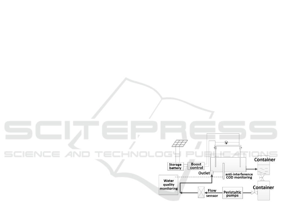
In order to remove the refractory substances in
the wastewater, it is necessary to electrolyze the
wastewater with impulse voltage in the water
treatment industry. In fact, this is applying periodic
voltage to the wastewater intermittently according to
the law of time. The width and frequency of the
periodic voltage can be adjusted according to the
pollution condition of treating water and the
corrosion resistance of the electrode. The structure
of the sewage treatment control system based on PV
electrochemical catalytic oxidation is shown in
Figure 1.
2. SYSTEM DESIGN
This design uses PLC technology to realize the fully
automatic three dimensional rotation of photovoltaic
panels tracking the sun and it also uses SCM
technology to control the energy storage of
photovoltaic panels and the automatic adjustment of
high voltage pulse, which breaks through the
technology bottleneck that the electrode is easily
vulcanized and the service life is shortened during
the use of the electric storage appliance.
Figure 1: The structure of the sewage treatment control
system based on PV electrochemical catalytic oxidation.
2.1 Light Tracking System
Using IC200UDR040-CC as a system controller,
this system can process the incident angle of the
solar light collected by the light tracking device to
control the DC motor and adjust the angle of solar
energy plate. Realizing the function of solar energy
plate tracking solar light automatically can make the
solar energy plate face to the sun automatically,
which can improve the efficiency of photovoltaic
conversion in photovoltaic system.
There are two modes in this control system:
testing and running. In the running mode, the light
signal is converted to the electrical signal through
the photosensitive sensor, and PLC control system
receives the electrical signal and then it controls the
motor rotation. The photosensitive resistance is used
as the photoelectric sensor and the circuit is
controlled by the characteristic of the photosensitive
resistance when it meets light that makes the
resistance smaller and current conduct. Four groups
of photodiodes detect four directions respectively
through special devices, so that the system can
determine the direction of the sun by judging
whether any of the four groups of photodiodes is
illuminated. Combined with a mechanical device, it
can track sunlight. PLC determines the current state
by the instruction of the test / run button. In the
testing mode, we can control the lighting of the three
analog light sources by manual buttons to determine
whether the operation of the program and the
hardware device is normal and to test the stability of
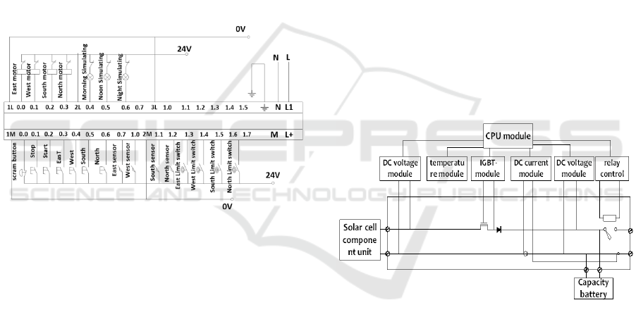
light tracking. The PLC wiring diagram of the solar
light tracking system is shown in Figure 2.
Figure 2:The PLC wiring diagram of the solar light
tracking system.
The control system determines the stopping
position automatically according to the wind speed.
When there is no wind, it does real-time tracking in
the daytime and stays at 15 degrees in the elevation
at night to ensure that the condensate can flow
down. When there is a wind, it returns to the initial
horizontal position to reduce wind resistance. The
control system switches between the day and night
modes automatically according to the time. When
the system time is in the night time, the solar light
tracking motor is in a stop working state. When the
system time is in the daytime, the motor is in a
working state.
2.2 Energy Storage Control System
This system is mainly used to detect the output
voltage and current parameters of photovoltaic cells
and control over charging, balanced charging and
float charging to the battery through the DSP.
Meanwhile, it supplies power to the DC load by
judging the over discharging protection, over current
protection, under voltage protection and other
situations in the discharging technology of storage
battery.
The system analyses and processes the collected
data of the system clock, the working state of the
electric storage appliance and so on. When there is
continuous rainy weather and the electric storage
appliance lacks power and it is unable to obtain solar
energy, the controller quickly cuts off the
discharging circuit of the electric storage appliance
and switches on the high voltage input side of the
stand-by power to provide energy for the electrolysis
system. The input side and the high voltage power of
the standby power are always in a state of circuit
breakage, so that there is no energy consumption of
the standby power. The system is consist of solar
cell component unit, DC voltage acquisition module,
temperature acquisition module, IGBT-driving
module, DC current acquisition module, relay
control module, battery pack, DC load,
communication module and so on. Figure 3 is the
schematic diagram of the electric energy conversion
system.
Figure 3:The schematic diagram of the electric energy
conversion system.
2.3 Pulse Control System
The main power supply methods of electro-catalytic
oxidation wastewater include DC power supply and
pulse power supply. The effect of sewage treatment
by pulse electrolysis can be maintained, whose
energy consumption is lower than DC electrolysis.
In addition, impulse action can reduce sediment on
the surface of the plate and maintain high current
efficiency. According to the technical requirements
of the catalytic oxidation of sewage treatment
process and the design index of the impulse power
supply, a pulse bias power supply with a frequency
range of 10-40 kHz and a rated power of 1kW is
developed. The duty ratio is continuously adjustable
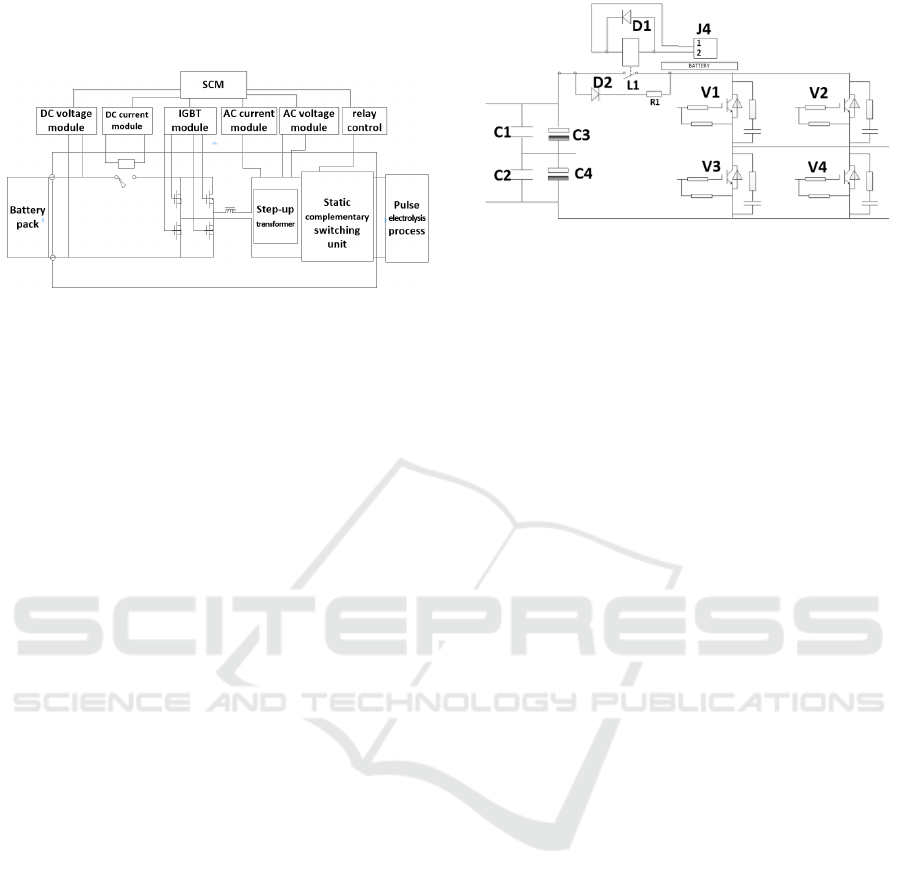
in the range of 10%-60%. The schematic diagram of
the control unit is shown in Figure 4.
Figure 4: The schematic diagram of the control unit.
Based on the control technology of SCM, IGBT
with high frequency high pressure resistance and
PWM, using high frequency transformer, this system
proposes a new system structure suitable for high
power pulse power supply. This design is made up
of voltage regulation circuit, full bridge inverter
circuit, high voltage rectifier and filter circuit, pulse
voltage output circuit and protection and control
circuit. Full bridge inverter circuit is the core part.
The single-phase full bridge inverter circuit of
Figure 5 is the inverter circuit. The V1 - V4 in the
diagram are the main inverter switch tubes. This
circuit uses voltage source type inverter—VSTI. The
DC side is the voltage source. There is a smooth
capacitor with a rectifier and filter circuit in front of
the reverse bridge, which can make the DC circuit
appear low resistance and make the DC side voltage
stable and smooth without voltage fluctuation
basically. This can provide a smooth DC current for
the full bridge inverter circuit. The DC conversion
circuit also determines and switches inverter input
current through the controller, according to the state
of the battery. And meanwhile, it can test whether
the input current meets the conversion condition
through a Hall current sensor to ensure the stability
of the output pulse signal. In this design, there is a
resistance between the grid and the emitter of the
IGBT, which is made close to the emitter,
restraining the overvoltage between the collector and
emitter. In the end, the high frequency transformer is
used to make the output voltage variable in a certain
range. And the frequency can be adjusted by the
SCM in order to meet the requirements of different
wastewater treatment.
Figure 5: Single-phase full bridge inverter circuit.
3. CLOSING REMARKS
A control system for sewage treatment based on
solar electro catalytic oxidation method is talked in
this paper, which can track the sun by the fully
automatic three dimensional rotation of solar panels
and increase the utilization of solar energy. The
design of battery charging control mode and the
automatic adjustment and control of electrolysis
pulse voltage of wastewater can reduce energy
consumption and prevent electrode corrosion
effectively.
New energy photovoltaic technology is in the
early stage and electrolysis wastewater with pulse
method is an important tendency in waste water
treatment. With the continuous development of the
use of equipment and the improvement of the
stability and reliability of pulse power supply, this
system will play a positive role in water treatment.
ACKNOWLEDGEMENTS
Fund projects: Scientific research project of Tianjin
Jinnan Science and Technology Commission 《
Design of self purification system for underground
water storage system in sponge city with green
energy》(20180120)
REFERENCES
1. ShenJie.(2011)The design of solar tracking system
based on PLC[J]. Industrial control computer,
2011( 11) :36-38.
2. Haiping Luo; HuiLi; Yaobin Lu; Guangli Liu; Renduo
Zhang.(2017) Treatment of reverse osmosis
concentrate using microbial electrolysis desalination
and chemical production cell[J].2017(4): 52-
9.

3. Zhi-junHu;You-mingLi.(2011)A Combined
Electrocoagulation electrooxidation Treatment on
CTMP Wastewater [ J ].Advanced Materials
Research 233-235.1: 619-22.
4. WangDong, xieChenxin. (2017)Research on the
treatment of domestic sewage by maritime mobile
facilities [ J ].Industrial Water Treatment
Vol.37No.12017(1).
5. Fan Chunyan.(2011)Design of high frequency and
high voltage pulse power supply controller for crude
oil dehydration [ J ]. Automation in
petrochemical industry,2011( 2) :48-50.
6. Zhou,Jing ; HeWei.(2011) Intelligent charging
controller of battery-buffered stand-alone photovoltaic
system[J].Electric Power Automation Equipment,
2011(11) : 13-17.
7. Kotha, Venkateshwarlu .Maximum power point
tracking with fuzzy logic approach for grid
connected photovoltaic system [ J ] .
International Conference on Industrial and
Information Systems, 2010 (5) : 586-589.
APPENDIX
A brief introduction to the author: Shen Jie(1981-),
female, was born in Hefei, Anhui. She is an
associate professor with a master’s degree in control
engineering. She is the director of the new energy
development center and is engaged in research on
photovoltaic system control and energy saving
engineering.
Tel:13920165996; E-mail:sj_tina@126.com
