
Application of Integrated Device for Produced Liquid Preliminary
Separation and Desanding in Oil Field Production
Junpeng Zhou
1
,Xiaoxi Chang
1
and Xindi Zhou
2
1
Daqing Oilfield Engineering Construction Co., Ltd. ,Kunlun Street 75,Ranghulu Daqing,Heilongjiang,China P.R.
2
School of Electrical and Electronic Engineering ,Harbin University of Science And Technology,Xuefulu Road 52,Nangang
Harbin,Heilongjiang,China P.R.
Keywords: Integrated device , Skid-mounted , Design applications
Abstract: At home and abroad ,there is a large number of theoretical and experimental research on hydro-cyclone
separation equipment, of which the research on the multiphase hydrocyclone desanding device already has
certain theoretical basis. In Daqing oilfield, desanding technology and equipment was adopted in the
produced fluid gathering and transferring process . This paper mainly introduces the application of sand
removal equipment in the oil field research.
1 INTRODUCTION
After the development and production of Daqing Oil
Field entered the stage of high water cut period,the
produced fluid composition changed a lot and the
composition became more complex. To improve oil
recovery, many key technologies, like chemical
flooding, are applied and thus lead to the obvious
sand content in the produced fluid. Long-term oil
field production practice showed that sand
deposition appears in the three-phase separator in the
process of the oil and gas gathering and
transportation and influences the oil-water
separation. This will cause severe scaling in the
heating furnace and finally lead to burning failure of
the equipment at an early stage.To solve the above
problem, preliminary separation and desanding
technology was applied in Daqing oil field produced
fluid gathering and transportation process and
special integrated equipment was designed. This
paper mainly introduces the application of integrated
device in oil field production.
2 TECHNOLOGICAL PROCESS
2.1. The Application of the Existing Sand
Removal Device
Sand Removal Device ( SRD) was specially
designed in Daqing Oil Field in the previous
produced fluid gathering and transportation process
and this causes mud existence in the whole process
and thus lead to a series of problems. To place the
preliminary separation and desanding device in the
upstream part of the gathering and transportation
process , that is , before the three-phase separator, is
expected to minimize the negative impact of mud
sediment on the gathering and transferring process.
Structure principle and process flow of the
existing design prototype are shown in Figure 4.
Sediment by cyclone desander after separation from
the bottom, to facilitate the separation of sediment
accumulation, clearance and observation,
sedimentation tank in the swirl portion of the bottom
sediment design, part of the settlement tank in the
upper left part of the cyclone underflow and
sediment, sedimentation tanks.
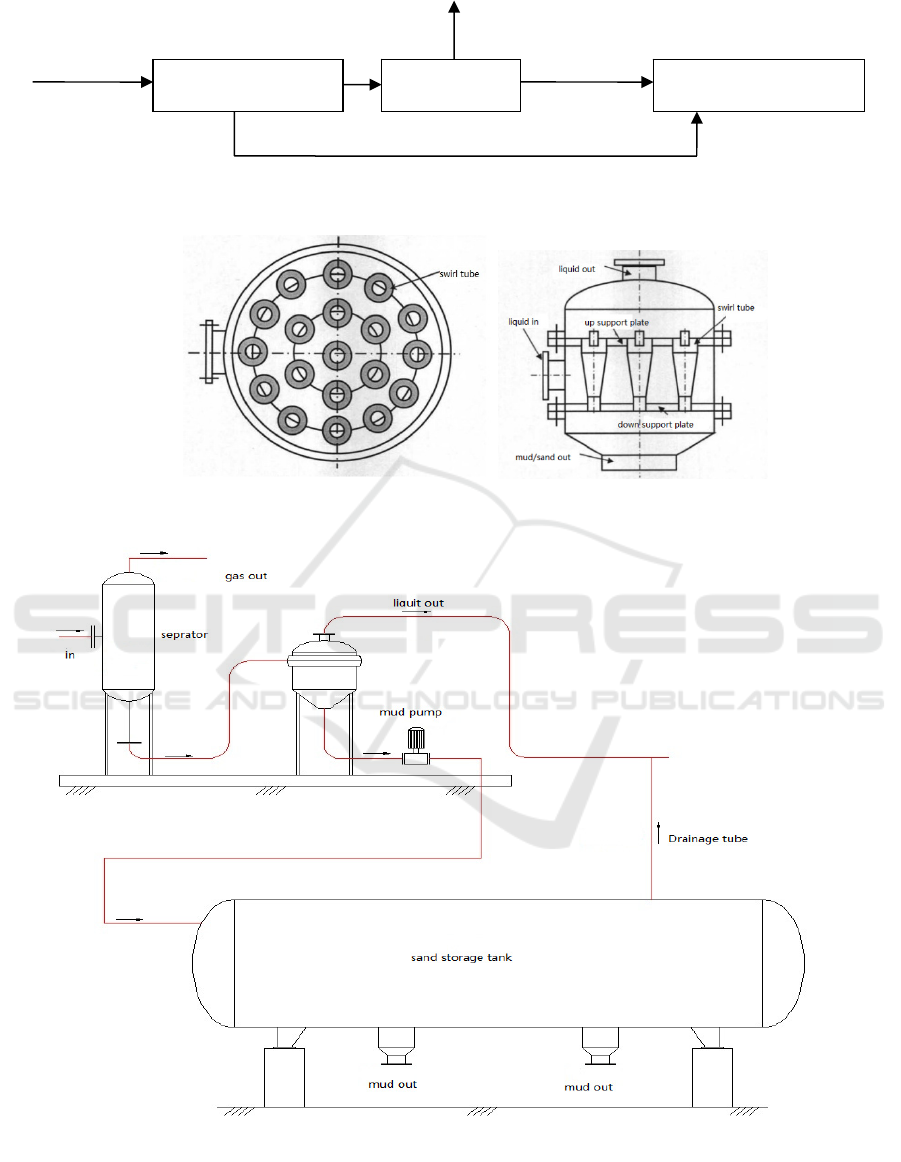
Figure 1 process schematic diagram.
Figure 2 overlook structure . Figure 3 front section view.
Figure 5 device layout.
Oil 、 gas 、
wate
r
Gas-liquid
se
p
arator
Sand removal
device
Three phase
se
p
arator
Oil 、 gas 、
wate
r
Gas
(p
art
)
s
and
Oil, a small amount of gas, water

2.2. Improvement of Integrated Sand
Removal Device(ISRD)
Although the original prototype is convenient for the
separation of sediment after separation, it also brings
many unfavorable problems to the operation of the
equipment. Because the SRD is arranged on the
upper part of the sediment settling tank, the total
height of the sediment settling tank is about 4~5
meters, which will cause the pressure drop of the
system to increase by 0.04 to 0.05MPa. The normal
production of the oil station basic working pressure
0.35~0.4 MPa, increasing desanding integrated
device equals the pressure drop increased by 10% to
12.5%, due to the pressure drop device compared
with the general assembly have an impact on the oil
field ground process system, the most direct is the
super pressure safety valve, therefore need to be
solved to increase integration device system after
increasing the pressure drop problem.
Because the cyclone SRD needs to consume a
certain amount of energy to obtain the swirling flow
power, under the current conditions, the system
pressure drop caused by the best efficiency of the
integrated device is inevitable. Therefore, the system
pressure drop of the whole integrated device is
reduced by reducing the static pressure of liquid
column in the main stream.
The optimized layout of the ISRD is shown in
Figure 5. The sand is arranged in the division level
or above, through the mud pump after the separation
of sand and sediment discharge to the settling tank
lifting. Without affecting the normal process, the
pressure drop of 0.04 ~ 0.05MPa due to the height
difference is reduced. At the same time, by adding
the sludge pump to compensate the pressure drop of
the system, although the investment has increased, it
ensures the feasibility and stability of the operation
of the whole device.
3. ISRD UNIT PRYING AND
MOUNTING
With the continuous improvement of the
construction technology of the oilfield ground
construction, the integrated integrated device is also
used in Daqing oilfield to be used in the existing
process. This set of SRD has skid mounted design,
which integrates mechanical technology, electrician
technology, automatic control technology and
information technology. It has the advantages of
saving investment, saving land, convenient
transportation and installation, high reuse rate and
shortening construction period.
3.1 Skid Design
The dynamic equipment, the static equipment, the
process pipeline, the valve instrument and the
electrical control are put on the joint sled seat to
form an integrated integrated device. Consider the
following main design factors: one is the application
of advanced design method, optimization of
combined skid in space, so space utilization
efficiency, operation and maintenance of reasonable
space; two is the selection of small and efficient
equipment, coordination and optimization of
equipment and piping of the opening, the application
of multi way valve piping installation structure is
simplified; the three is for the convenience of
transportation, reasonably determine the skid the
size of a single skid base length should not be more
than 15 meters wide, not more than 2.8 meters, a
large device can adopt multiple skid joint
assembling form; four is to consider the overall
layout of the device more stable to prevent the lifting
process and overthrow.
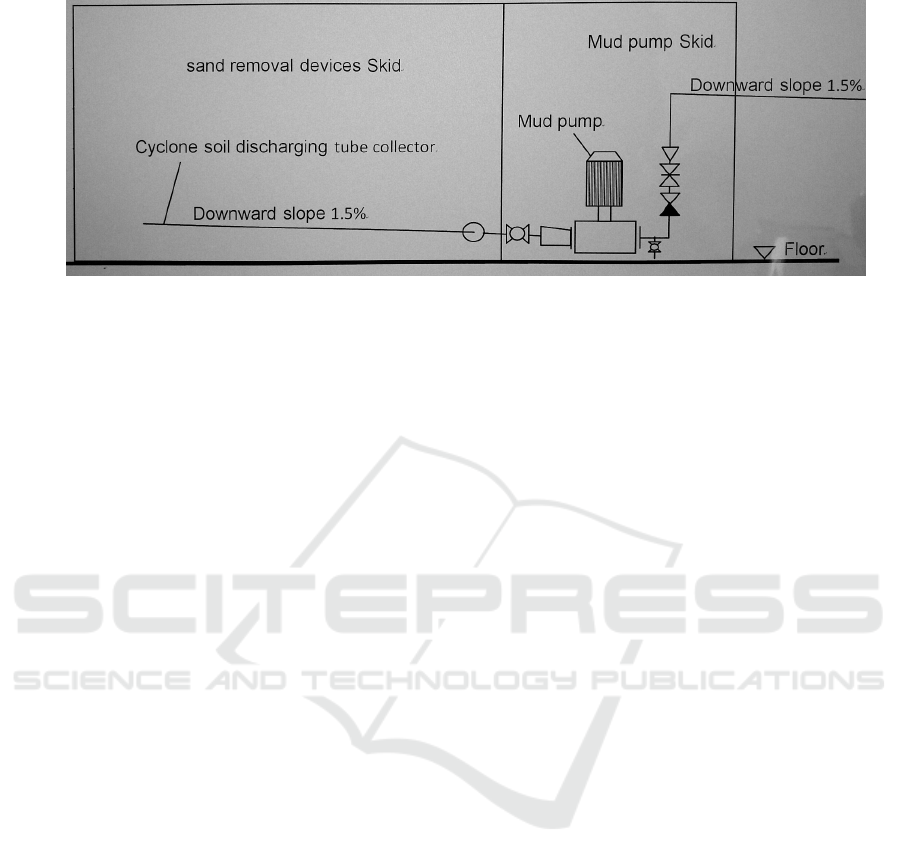
3.2 Design Example
As shown in the Figure 6, the oil and gas separation
and SRDs are used as a sled unit, and the sludge
pump itself becomes a sled unit. The construction
period can be shortened greatly, and more than 80%
of the field work can be reduced. In the actual
application process, sometimes it is necessary to
place the mud pump skid outside. Considering the
environmental requirements of winter operation in
Daqing area, we will upgrade the pump to a
pumping room with features of skid mounted (its
design meets the specific requirements of fire
protection and explosion-proof regulation).
At the same time, the whole device sets the heat
tracing system, the heat source adopts the heating
furnace inside the station, the device and the outside
of the pipeline use the insulation material for heat
preservation treatment. In the process of practical
application, the device is part of the process system,
and the medium of the device is in the state of
operation, which can meet the demand of winter
operation. Considering the device some exposed
instrumentation components affected by low
temperature, there will be a bad situation with heat,
pressure transmission device failure, affecting the
normal operation of the device, so it is necessary to
take measures to increase the electrical heating of
key components, in order to avoid the disadvantages of low temperature operation.
Figure 6 design example.
4. CONCLUSIONS
The integrated device for separating and removing
sand from the produced liquid has the characteristics
of integration and automation. It can realize
standardized design, modular precast and automatic
control, and is suitable for the production of similar
produced liquid in Daqing oilfield and other cold
regions. Through field tests, the data show that the
application of the pre-distributary sand removal
process and the installation of special integrated
equipment can effectively reduce the sediment
content of the produced liquid and greatly improve
the treatment effect of the subsequent three-phase
separator.
With oil production to the standardized, modular,
intelligent direction, such as the pre diversion sand
special integrated device developed into crude oil
desanding proprietary technology products,
effectively saving investment, saving land,
transportation and convenient installation, high
recycling rate, shorten the construction period and
other advantages, will have broad application
prospects.
REFERENCES
1. Li Fulin, Wu Jiming, Ho Limin. Simulation screening
of multi division sand separator structure. Oil and gas
field surface engineering, 2004; Vo1.23 (6): 12 ~ P11
2. Zhang Haiyan, Li Ming, Tian Ying men. Original sand
removal technology, oil and gas field ground
engineering, 2008; 27 (11): P76
3. Da Yu, Wanyan Cao, Multi phase swirl removing sand
in Daqing oilfield application D. China University of
Petroleum, 2018.
