
Elliptical Gear Dynamic Analysis Based on ANSYS Workbench
Jian Zhang
1
,Peng Rao
1
,Bin Zheng
1
and Xuemei Qi
1
1School of Transportation and Automobile Engineering, Panzhihua University, China
Keywords: Elliptical gear; parametric modelling; dynamics; Pro/E; ANSYS.
Abstract: Aiming at the problem of 3D parametric modeling and dynamic analysis of elliptical gears, an elliptical gear
was taken as the object of study, and the three - dimensional parametric modeling of elliptical gear was
realized by combining MATLAB parametric design and Pro/E entity. Through the modal, harmonic
response and transient dynamics analysis of the elliptical gear by using ANSYS, the first six natural
frequencies of the elliptical gears and the distribution modes of the main modes and corresponding
displacement response curves, strain cloud maps and stress response curves were obtained. The results of
dynamic analysis show that the elliptical gear stress and deformation are more serious suffered in the
direction of long diameter, keyway direction and keyway, so it should be considered in the design and
optimization of elliptical gear.
1 INTRODUCTION
Elliptic-gear pitch curve is irregular, therefore it is
quite difficult to determine each-tooth direction and
position, which greatly increases the difficulty of
modeling 3D and reduces the efficiency and
precision [1]. Study on kinematics characteristics of
mechanical movement parts gets vibration
characteristic through modal analysis to provide
fundamental analysis data for harmonic response,
transient dynamics, which judges the rationality of
gear pair design and weak position, provides
reference for optimal design, for example, elliptical
gears pair[2-3]. With unique non-linear dynamic
characteristics, elliptical-gears dynamic analysis is
more complex compared to circular gears [4-8].
In order to improve the modeling accuracy and
efficiency of elliptical gears, parameterized hybrid
modeling of MATLAB and Pro/E was used. Modal,
harmonic response and transient dynamics analysis
were analyzed by using ANSYS Workbench. Then
the dynamics parameters distribution regularities
were obtained, and found out the elliptic gear stress
concentration and easily damaged parts to provide
reference for elliptical gear and other non-circular
gear design and optimization.
2 ELLIPTIC GEAR MODELING
Table 1: The elliptic gear basic parameters.
Gear parameters Value
Order n
1
2
Eccentricity e
1
0.6
Number of teeth Z
2
45
Breadth tooth b(mm) 14
Addendum coefficient 1
Root clearance coefficient c 0.25
Modulus m(mm) 3
Angle of pressure α(°) 20
Elliptic gear design flow chart is shown in Fig 1.
According to the Fig1, 2 order elliptical solid
model is established by using MATLAB and Pro/E,
as shown in Fig 2, and its basic parameters are
shown in Table 1.
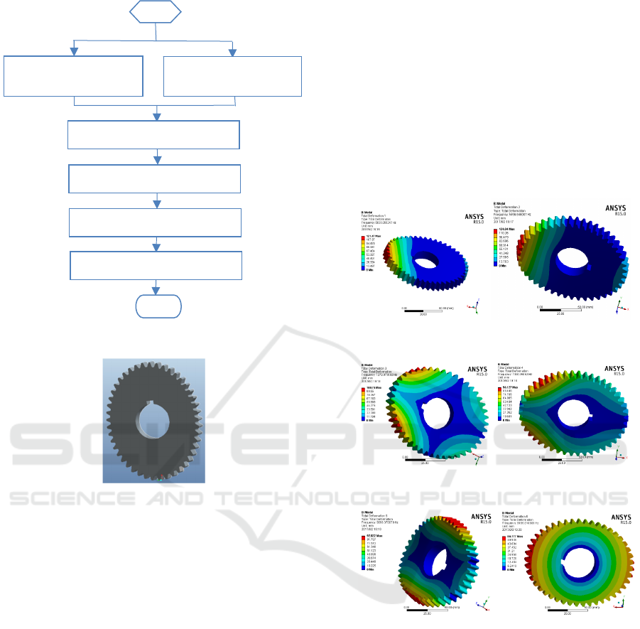
Figure 1: Elliptic gear design flow chart.
Figure 2: Elliptic gear model
3 MODAL ANALYSIS
3.1 Modal Analysis Theory
Modal analysis, that is, free vibration analysis and a
modern method for studying the structures dynamic
characteristics, which can be used to determine
natural frequencies, vibration mode and vibration
mode participation coefficient, which is how much
extents some vibration mode participates in
vibrating in a certain direction.
For modal analysis, the analytical formula is:
[] []
()
{}
0-
2
=
ii
MK φω
(1)
In formula (1), φi is modal; ωi is vibration
frequency ; K is stiffness matrices; M is mass
matrix.
Elliptical-gear natural frequency and each order
vibration mode are infinite, while each natural
frequency and corresponding main vibration modes
represent the free vibration modal of a single
freedom system. This modal is non-circular gear
basic vibration characteristics which plays a decisive
role in low order mode. Therefore, it is only
necessary to analyze the modal vibration of elliptical
gears under low order natural frequencies when we
perform modal analysis.
3.2 Modal Result Analysis and
Evaluation
(a) One order mode (b) Two order mode
(c) Three order mode (d) Four order mode
(e) Five order mode (f) Six order mode
Figure 3: Modal vibration modes
The material of the two order elliptical gear is 45
steel, the mesh cell size is 10mm, torque is 105 N•m,
the phase angle is 0. Through modal analysis for
inner hole constrain conditions, six vibration modes
and their natural frequencies are shown as Fig 3.
Below the graphics window of “Mechanical” ,
natural frequencies of the models can be obtained, as
shown in Table2.
Define curve function
b
ased o
n
Elliptic geometry
The principle of cutting
tool
Tooth profile function
Draw profile figure by using MATLAB
Pro/E entity manipulation
3D model
End
Start

Table 2: Elliptical-gear natural frequency.
Mode Frequency [Hz]
1 5035.1
2 5456.6
3 7280
4 7390.1
5 9096.4
6 9195.8
According to Figure 3 and Table II, elliptical-
gear one order frequency is 5035.1Hz. The main
deformation is that X-axis positive direction teeth
tension and bend along the Z axis. The two order
frequency is 5456.6 Hz, the main deformation and
one order deformation are axisymmetric about the Z
axis. The three order frequency is 7280Hz, the main
deformation is left and right teeth X-axis positive
direction stretch and bending along respectively Z-
axis positive and negative direction ; The four
frequency is 7390.1 Hz,the main deformation is
that left and right teeth of X-axis negative direction
stretch and bending respectively along Z-axis
positive and negative direction; The five frequency
is 9096.4Hz , the main deformation is Y-axis
direction teeth symmetrically stretched and bending
along Z axis;The six frequency is 9195.8 Hz, the
main deformation is that the teeth in the long half
axle stretch along the angle between the X axis and
the Y axis. The reason is that the vibration frequency
generated by external excitation is close to elliptical-
gear natural frequency, initiating resonance.
Therefore , we should manage to avoid this
frequency range during design to improve gear life
span.
4 HARMONIC RESPONSE
ANALYSIS
4.1 Harmonic Response Analysis Theory
Harmonic response analysis is a technique used to
determine the steady-state response of linear
structures bearing load varying with time in
accordance with the sinusoidal (harmonic) rule. The
purpose of the analysis is to calculate response of
structure at several frequencies and obtain some
response values (usually displacements)
corresponding frequency curves.
The equation of motion of harmonic response is
:
[] [] []
()
{} {}(){}{}()
2121
2
-
FiFiKCiM
+=+++
φφωω
(2)
Setting up the stiffness matrices[K] and mass
matrix [M] are constant values, and the material is
linear, using small displacement theory (not
including non-linearity), damping is[C], and
harmonic loading is[F].
Harmonic response analysis aims to calculating
the response at the excitation frequency and
obtaining the frequency response curves. Gear
“peak” response can be found through the curve.
4.2 Harmonic Response Analysis and
Evaluation
The material of the two order elliptical gear is 45
steel, the mesh cell size is 10mm, torque is 105 N•m,
the phase angle is 0. The harmonic-response analysis
for gear inner hole conditions, we get the gear unit
of each order response angle and deformation,gear
unit each order frequency and phase angle,the gear
node change curve with frequency and displacement
response cloud map are shown as Fig 4.
(a) Each order response angle of gear unit
(b)Each order deformation curve gear unit
(c)Response frequency curve of gear unit

(d)Gear node change curves with frequency
(e)Displacement response cloud chart
Figure 4: Harmonic response analysis result
According to (a),(b), the elliptical gear
unit each order response angles and deformations
follow harmonic response equation, whose period,
input and output are same. According to(c),
with the increase of input frequency, each order
response frequency also increase, the phase angle
remains 180°, but it changes suddenly and sharply
reduced to zero near to the final value. According to
(d ),gear node response frequency curve and
phase angle change with frequency, and unit each
order response frequency and phase angle change
with frequency are the same. According to (e),
gear long axis direction displacement is larger,
especially the keyway direction. We can infer that,
in actual movement, elliptical-gear stress mainly
concentrates on keyway direction and the part where
the radius of curvature is longer. Thus, this part is
more vulnerable to damage. This part should
strengthen when processing.
5 TRANSIENT DYNAMIC
ANALYSIS
5.1 Transient Dynamic Analysis Theory
Transient dynamic analysis (also called time history
analysis) can be used to determine the dynamic
response while structures are subjected to arbitrarily
varying loads. Non-circular gears transient dynamics
can determine gear’s displacement, strain, stress and
force vary with time under the random combination
action of steady state load, transient load and
harmonic load.
The basic motion equation of transient dynamics
is:
)(
tFKuuCuM
=++
&&&
(2)
In formula (3) , M is mass matrix ; C is
damping matrix ; K is stiffness matrices ; is
Nodal acceleration vector ; is Nodal velocity
vector;u is Node displacement vector.
In order to analyze whether two order elliptical
gear can bear low speed impact, some questions
such as vibration response caused by gear over
convex point need to do transient dynamics analysis.
5.2 Analysis and Evaluation of Transient
Dynamics Results
The material of the two order elliptical gear is 45
steel, and the mesh cell size is 10mm, torque is 105
N •m, the phase angle is 0. The harmonic-response
analysis for gear inner hole condition , we get
elliptical gear displacement and stress changes are
shown in Fig5.
(a)Deformation analysis cloud map
(b)Displacement response curve
u
&&
u
&

(c)Stress response curve
(d)Stress cloud map
Figure 5: Transient dynamic analysis result
According to ( a ),the gear long axis
deformation is bigger, especially the keyway
direction. We can infer that, in actual movement,
elliptical gear longer-pitch-diameter parts and
keyway direction are much more vulnerable to
damage. According to 5(b)and(c), elliptical
gear displacement and stress change synchronously
with time, the mutation at the starting point increases
sharply, and decreases with the passage of time.
According to(d), in actual movement, gear bore
diameter and shaft outer diameter interference fit
through. Bore diameter bear torque delivered by
shaft and produce stress. Because of the stress
concentration produced by the keyway, there is more
vulnerable to damage.
6 CONCLUSIONS
First, through modal analysis the first six nature
frequencies and principal vibration mode are
obtained by using ANSYS Workbench. The
vibration frequency produced by external excitation
is close to the nature frequency, which is vulnerable
to cause resonance. So, we manage to avoid this
frequency range during then design. Second, through
harmonic response analysis, pitch response
frequency curve and displacement response cloud
maps are obtained whose results show that stress is
mainly concentrates on the long diameter and
keyway direction. Therefore, this part is vulnerable
to damage. Finally, through transient dynamics
analysis, deformation and strain cloud maps and
displacement and stress response curves are
obtained. Elliptical gear stress and deformation are
more serious suffered in the direction of long
diameter, keyway direction and keyway, so it should
be considered in the design and optimization of
elliptical gear.
ACKNOWLEDGMENT
This work was financially supported by the
Education Department of Sichuan province in 2016
scientific research program of natural science project
(16ZB0482) and the national innovation training
program for college students (201411360016).
REFERENCES
1. Chaozhao Yan, Zhudian Guan, Yang Chen. Design
System of the High Order Elliptic Gear Pair Pitch
Curve based on the SolidWorks[J]. Journal of
Mechanical Transmission, 2017, (01): 169-172.
2. Yuchun Zou, Fang Ren, Jianzhao Yang. Harmonic
response analysis for main shaft device of single rope
winding mine hoist based on ANSYS Workbench[J].
Coal Engineering,2017, (03): 100-102+106.
3. Pingyong Liu, Cun Yang, Xuan Sun. Kinematics
Simulation Analysis of Non-circular Gear based on
ADAMS[J]. Journal of Mechanica Transmission,
2014,06:106-109.
4. Honggao Yu, Pingjia Yu, Huajia Tong. Design of a
conjugate concave-convex Non-circular Gear
Mechanism[J]. China Mechanical Engineering,2016,
(16): 2155- 215+2165.
5. Jun Liu, Haitao Liu. Mode Analysis of a 3-DOF PKM
module[J]. Journal of Machine Design,2017,(04):17-
23.
6. Zhong Liu, Weizhan Gao, Minghuan Huo. Vibration
Mode Analysis of Valve Controlled Cylinder Type
Hydraulic Elevator[J]. Machine Tool &
Hydraulics,2017, (01):125-128.
7. Nantie Liu, Yansong Tian, Yusu Liang. The transient
dynamics analysis of monorail car rail unit[J]. Chinese
Journal of Engineering Design,2016, (04):352-35.
8. Lilin He, Li Hou, Li Bo. Dynamic Analysis of
Cylindrical Gear with Curvilinear Shape Teeth Based
on UG and ADAMS[J]. Modular Machine Tool &
Manufacturing Technique,2016, (04): 12-15.
