
Mechanical Structure Design and Dynamic Simulation of Rail Car
Guiliang Xie
1
, Yanmei Luo
2
and Guoyan Yu
2
1.EngineeringCollege, Guangdong Ocean University, Zhanjiang 524088, China
2.Marine equipment manufacturing and engineering technology research center of Guangdong province
,
Zhanjiang
524088, China
Keywords: Rail car, mechanical structure, Adams, virtual simulation prototype, self-adaptive
Abstract: Based on the analysis of the mechanical structure of the traditional rail car, a new type of rail car is
proposed with the actual operation requirements. The mechanical structure design with the front wheel
guiding mechanism ,body steering bearing mechanism and a new self-adaptive mechanism respectively,
which could enable the car to run normally in the deformed rail and optimize turning performance of the car
.The parameters of the self-adaptive mechanism and the required torque are analyzed from the kinetic view,
and an accurate and reliable virtual prototype model was established through combining the virtual
prototype technology with Pro/E and Adams modeling simulation. The simulation results show that the
design of the virtual prototype model is consistent with the mathematical model along with the friction is
reducing significantly when turning the car and the function that self-adaptive deformed rail is realized. This
verifies the rationality and practical feasibility of the mechanical structure for this rail car which also
provides a useful reference for the further development of the rail car prototype.
1 BACKGROUND
With the rapid expansion of the industrial scale of
factory aquaculture, high precision, convenient and
economical rail-type automatic feeding system has
rapidly become a research hot spot. Now like Arvo-
Tec 、 Strovik 、 TransFeed 、 Crystalvision etc.
international companies had developed the rail car of
the rail-type feeding machine with high precision,
low noise, long service life and other characteristics.
In contrast, China hasn't begun to do research on
rail-type feeding machine until recent years. Due to
the long distance of the guide rails, there are some
problems with the car such as wheel suspended and
wheel-slip as a result of manufacturing and
installation errors, and the wheel on the rail bend
would get stuck easily; In a way ,the car can’t run on
a rail with flexible deformation, which affects
automatic feeding robot accurate positioning and
bait throwing. The innovative structures of the self-
adaptive rail car, which is a kind of automatic
breeding equipment, not only solve the running
problem of factory aquaculture rail car but also
improve the automation level of factory aquaculture
by mechanical design and virtual prototype
platform[1-6]. Different from the traditional factory
aquaculture rail car, the rail car proposed in this
paper has the following two characteristics :①a
new self-adaptive mechanism is used to enable rail
car to run normally in the deformed rail. ②The
turning angle of body steering bearing mechanism
can be adjusted according to the turning radius of
rail and optimizing its turning performance. In order
to verify the rationality and practical feasibility of
the design, the virtual simulation platform has been
done by using virtual prototype technology, the
parameters of each mechanism and the operation of
each mechanism has been analyzed and determined.
Then making a judgment and giving suggestions for
optimization on rationality of mechanical structure
design of rail car.[7-10]
2 STRUCTURAL DESIGN OF
RAIL CAR
2.1 The Front Wheel Guiding
Mechanism
The guiding wheel of the guiding mechanism
contacts with the side surface of the rail when the
car turns. The guide shaft, the guide plate and the
connecting rod provide the force to make two front
wheels turn synchronously. Compared with the
conventional flange structure, this structure reduces
the friction force when the car turning and increases
the torque that the front wheels need in
turning phase, which would be better for car turning.
In order to accommodate different radius of bend,
the variable angle between two guide plates could be
adjusted according to the bend radius.
2.2 Body Steering Bearing Mechanism
The functions of steering bearing mechanism are as
follows:When the car sensor detects the corner
limit switch, The electric control device makes the
electric push rod work to push the steering bearing
rotating for a certain angle in the opposite direction
of the rail bend, which could drive the rear wheels
assembly to rotate for a certain angle in the opposite
direction of the rail car;When the front wheels of
the car leave the rail bend,the car sensor detects
the limit switch of rail bend, the electric push rod
pushes the body steering bearing mechanism to
return to the original state. The body steering
bearing mechanism cooperates with the front wheel
guiding mechanism which could enable rail car
turning in a smaller radius along with reducing the
collision with friction between the flange of the rear
wheels and the rail, transient turning radius and
friction noise, so that the rail car could pass through
the railbend smoothly.
2.3 Self-adaptive Mechanism
The self-adaptive mechanism comprises the self-
adaptive wheel and the clamping mechanism,when
the rail car suffers from deformed rail or slipping,
the front wheel sensor will send signal to PLC
thought detecting the car is in a non-running state.
Then PLC controls the electromagnet of the
clamping mechanism to work, therefore, the slider is
embedded with the groove of the ratchet, and the
ratchet is screwed in so that the bevel supports
wedge extending outwardly until the wedge is in
good contact with the rail and the car resumes
walking. PLC controls the electromagnet of the
clamping mechanism pushes the slider to retract and
stops the self-adaptive mechanism when the car
sensor detects the car is in a running state. Finally,
the rear wheels return to normal running. Through
the cooperation of the PLC and the self-adaptive
mechanism, the rail car could work normally in the
deformed rail.
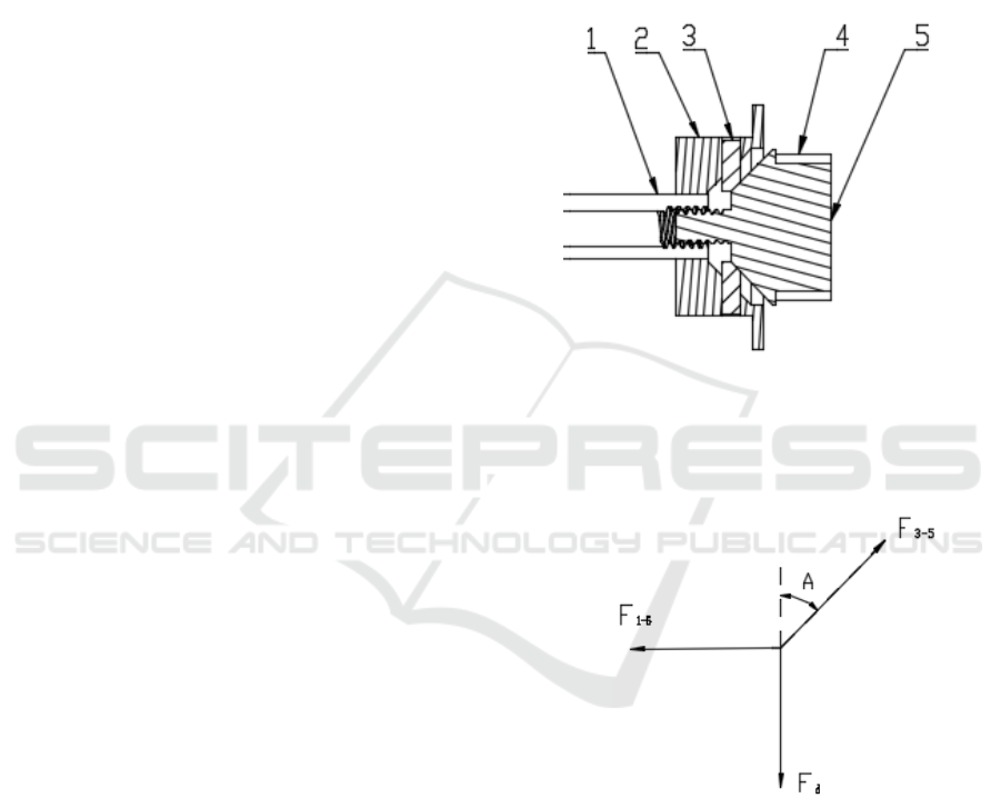
3KINEMATIC ANALYSIS
The rail car adopts the self-adaptive wheel as shown
in the figure, the self-adaptive mechanism is control
to be turned on and off by the cooperation of the
PLC and the clamping mechanism. The self-adaptive
wheel consists of a ratchet, a wheel hub and a wedge
.with the requirement of practical task ,the car loads
90 kg, running velocity is 18 m / min.
Figure 1:Partial structure of self-adaptive wheel 1.axle 2.
Wheel hub 3.wedge 4.groove 5. Ratchet.
Force analysis:
To ratchet
Figure 2: Force analysis of ratchet.
To wedge
= (1-1)
F
=F
(1-2)
F
=F
∗sinA (1-3)
F
=F
∗cosA (1-4)

Figure 3:Force analysis of wedge .
Solution of equation:
=
(1-5)
let
o
45=A
than
GF =
5-1
Assume the rear wheel loading 1000N, the screw
thread of the wheel axle adopts a left-handed
rectangular screw thread, friction coefficient of
thread friction joint[11] : u=0.1
5-1
F
is provided by the screwing force of the thread,
the working principle of the screw transmission joint
is as follows:
Figure 4:Principle of screw transmission joint.
Figure 5: Resistance.
According to mechanical principles[12]
F=G∗tan
A+B
=1000×tan20.7≈400N
(1-6)
M=F∗
=100×
=4000. (1-7)
Because
A
B
>
not self-locking, the ratchet will
return to the original position, when the clamping
mechanism is closed.
Because the adaptive wheel will generate a
torque resistance when it extends out of the wedge
=sin
360
12
2
×90×1000≈25000.
(1-8)
T=
+≈30000. (1-9)
4 RAIL CAR MODEL
Adams software has a strong dynamic simulation
function ,and Pro/E has powerful modeling
capabilities which can build a variety of complex
models, this paper combines the advantages of both,
Pro/E is used for modelling and the dynamic
simulation analysis is carried out in ADAMS.
Creating a model with Pro/E and Adams is a process
of continuous improvement, 3D solid modeling
includes two steps: part modeling and the car model
assembling, according to the structure characteristics
and functional requirements of the rail car to
complete the modeling and assembly along with
obtaining the 3D solid model. Rigid bodies and
constraints are defined by the interface program
Mechanism/Pro between Pro/E and ADAMS, then
the 3D solid assembly model established by Pro/E is
converted into ADAMS which could further perfect
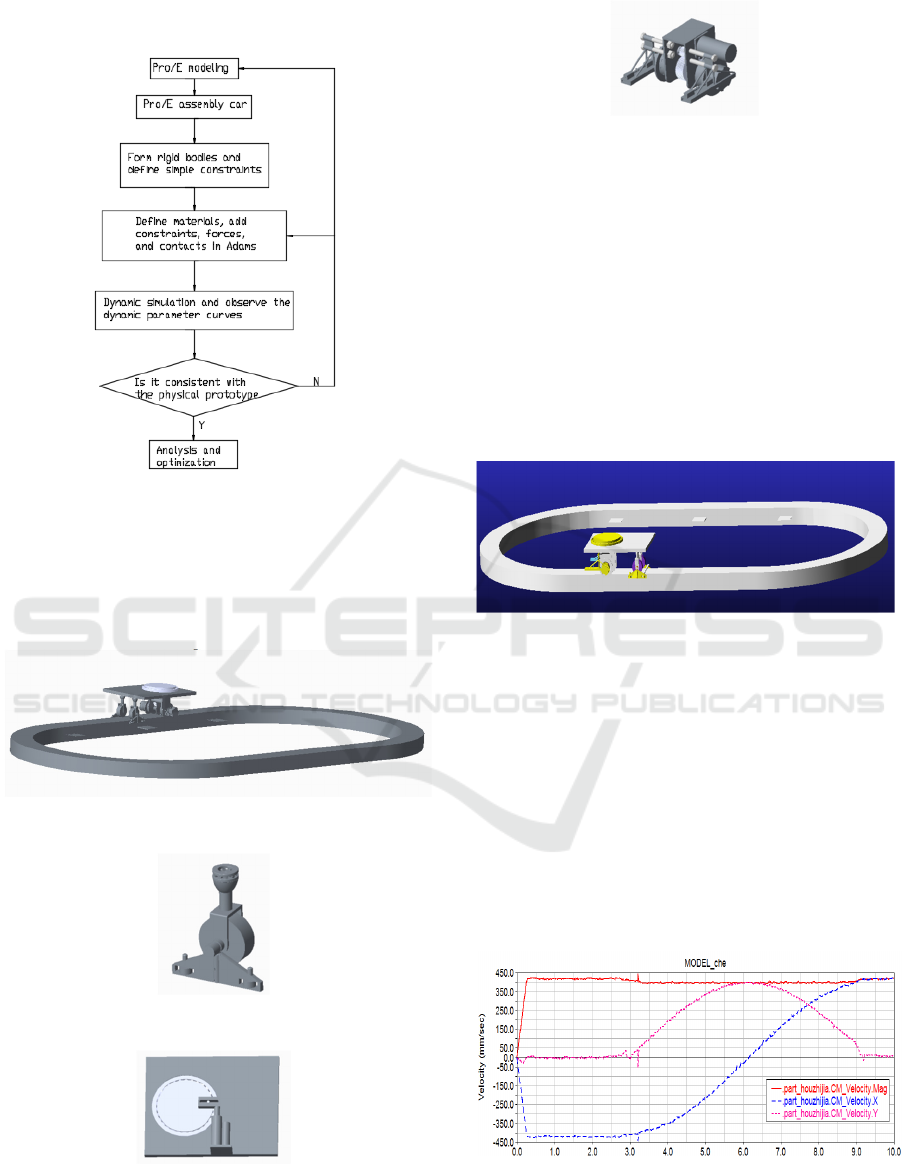
ADAMS dynamic model. The specific modeling
steps are shown in figure 6.
Figure 6:Modeland simulation block flow sheet
4.1 Pro/E Model
The mechanical structure of the self-adaptive rail car
is modeled by Pro/E software . Figure 7 is a part
model of the rail car. Figure 8 is Pro/E model.
a. Rail car assembly
b. The Front wheel assembly
c. Body steering bearing mechanism
d.Self-adaptive mechanism
Figure 7: The mechanism of each part and the general
assembly model of the car
4.2 Adams Virtual Prototype Modeling
Simplifying the Pro/E model and importing it into
ADAMS. Generating the ADAMS model by the
interface software mechpro2005 between ADAMS
and Pro/E. Then combining the parts without
relative motion in ADAMS with Boolean sum,
defining material properties, constraints, forces,
contacts, and motions.
Figure 8:Adams model
5ADAMS DYNAMIC SIMULATION
AND ANALYSIS
5.1 Bend Running Simulation
The simulation conditions assume that the rail car
that loads 900N running on an annular rail which the
straight line is 1.5 m and the bend radius is 0.8m.
The car velocity curve and the car friction curve are
shown in Figure 9-12.
Figure 9: Relationship between car velocity and time
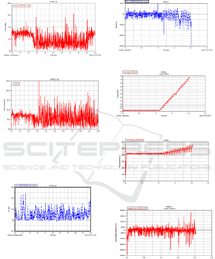
Figure 10: Friction of rear wheels in bend with body
steering bearing mechanism
Figure 11: Friction of rear wheels in bend without body
steering bearing mechanism
During the turning phase, the friction of the rear
wheels with body steering bearing mechanism is
about 35N, and the friction force of the rear wheels
without body steering bearing mechanism is about
65N.
Figure 12: Relationship between front wheels friction and
time
5.2 Self-adaptive Running Simulation
Figure 13: After the self-adaptive mechanism working,
the required torque of rear wheels
Figure 14: The displacement of CM of the rear wheels in
the vertical direction
Figure 15: The car velocity with the self-adaptive
mechanism working
Figure 16: The car accelerated velocity with the self-
adaptive mechanism working

6 RESULT
Figure 9 reflects the straight running and bend
running of rail car with the stable velocity, which
shows that the front wheel guiding mechanism and
the steering bearing mechanism meet the design
target. Figure 10-12 reflects that the friction is
relatively stable whether the rear wheels or the front
wheels, the friction of the rear wheels is obviously
reducing with the improvement of using steering
bearing mechanism. Figure 13 shows the driving
torque of the rear wheels is accelerating after the
self-adaptive mechanism working. According to the
analysis, it can be seen that,the problem is due to
the torque resistance that generated by the extension
of the wedges and the increase of the car
acceleration, the data curve shows that the
simulation results within a reasonable range are
consistent with the kinematic calculation results.
Figure 14 show the CM of the car, with 0.5mm
fluctuations, gradually rises after the self-adaptive
mechanism working. This phenomenon is due to the
discontinuity between wedge and wedge of the self-
adaptive mechanism.Because the sampled
fluctuation peaks are relatively small for the entire
system. Therefore, there is little effect to the system.
Through analysis, a spring pad can be added to the
end of the wedges that contact with the rail to reduce
the degree of fluctuation, So that the system is more
stable.
According to the dynamic simulation results in
ADAMS, it can be analyzed that the front wheel
guiding mechanism and body steering bearing
mechanism can make the car running smoothly all
the way,and obviously reduce the friction of the rear
wheels when the car runs in the bend. There is slight
fluctuation of the CM of the car after the self-
adaptive mechanism working , improving the
contact surface of the wedge with the rail and add a
spring pad can reduce the degree of fluctuation.
From the perspective of dynamic mathematical
model, Adams simulation results are consistent with
the dynamic mathematical model, when the input is
the same, the dynamic simulation results are
consistent with the mathematical model results,
which shows that the new structure can meet the
design and the actual operation requirements.
7 CONCLUSIONS
In this paper, a new type of self-adaptive rail car is
proposed, the front wheel guiding mechanism, body
steering bearing mechanism and self-adaptive
mechanism are simulated and analyzed by using
virtual prototype technology, the relevant simulation
results show that Adams simulation results are
consistent with the dynamic mathematical model,
when the input is the same, the dynamic simulation
results are consistent with the mathematical model
results, showing that the new structure meets the
design and the actual operation requirements, which
provides a theoretical basis for the next step of
physical manufacture.
REFERENCES
1. FengT, et al, 2015. Development and prospect of
development and application of aquaculture
equipment in China.Chinese Aquatic Product.(07),
p.91-93.
2. Cui L, et al, 2014. Design and experiment of
automatic feeding system based on PLC for industrial
aquaculturetrack.Guangdong AgriculturalScience,
41(22),p. 159-165.
3. Wu Q, et al, 2015.Present situation and development
trend of fish feeding machine. Jiangsu Agricultural
Science, 43(10), p.458-461.
4. Liu S, et al, 2017. Research progress of automatic
feeding system for industrial breeding. Fishery
Modernization, 44(2), p.1-5.
5. Atoum Y, et al, 2015. Automatic Feeding Control for
Dense Aquaculture Fish Tanks. IEEE Signal
Processing Letters, 22(8), p. 1089-1093.
6. YUKINORIM, et al, 2016. Demand feeding system
using an infrared light sensor for Brown-marbled
grouper juveniles, Epinephelus fuscoguttatus. Sains
Mlaysiana, 45(5), p.729-733.
7. LiZ, 2014. Introduction to ADAMS and examples.
Beijing: National Defend Industry Press.
8. Fan J, et al, 2006. Application and improvement of
virtual prototype software MSC.ADAMS. Beijing:
Machinery Industry Press.
9. Zheng k, et al, 2006. Advanced application example of
ADAMS 2005 mechanical design. Beijing: Machinery
Industry Press.
10. Yu X, et al, 2006.Research on dynamic simulation
parameter setting based on ADAMS. Computer
Simulation, 23(9), p.103-107.
11. Wu Z, 2012. Mechanical design course design manual.
Beijing: Higher Education Press.
12. Department of mechanical principles and mechanical
parts, northwest university of technology, 2013.
Mechanical principles, 8th. Beijing: Higher Education
Press.
