
Effect of Heat Treatment on Mechanical Properties and
Microstructure of L80-13Cr Martensitic Stainless Steel
Yilong Zhang
1
, Wei Wu
1
, Bingbing Li
1
, Dezhi Yuan
2
, Kejian Li
1,3
,Kessam Shin
1,4
and Pengjun
Cao
1
1School of Metallurgy and Materials Engineering, Chongqing University of Science and Technology, Chongqing, China
;
2Steel Tube Co., Ltd., Chongqing Iron & Steel Group, Chongqing, China;
3The center of Material Analysis and Testing, Chongqing University of Science and Technology, Chongqing, China;
4School of Nano & Advanced Materials Engineering, Changwon National University, Changwon, Korea)
Keywords: Heat treatment, Martensitic stainless steel, Microstructure, Precipitation.
Abstract: L80-13Cr martensitic stainless steel (MSS) is a kind of oil casing steel. It has good resistance to carbon
dioxide corrosion and seawater corrosion, which makes it common oil casing steel in marine oil and gas
exploration. The effect of heat treatment on mechanical properties and microstructure of L80-13Cr MSS has
been studied. The specimens were analyzed using the micro-hardness test, optical microscope (OM),
scanning electron microscopy (SEM) and transmission electron microscopy (TEM). The hardness test
showed that the steel was secondarily hardened when tempering at 300 ~ 500°C. But continuous softening
occurred when the temperature was above 500°C. The martensite was recovered at temperatures around 300
~ 500°C, and higher temperature tempering (600°C) caused grain growth and even recrystallization. It has
been found that the precipitates in the steels that were tempered at 300°C, 500°C and 700°C, were need-like
Fe
3
C carbides, coarsed needle-like Fe
3
C carbides and rod-like or sphere-like Cr
23
C
6
carbides. Especially
when tempered at 700°C, the Cr
23
C
6
carbidesprecipitation along the marten site lath was rod-like and
precipitation along grain boundaries was sphere-like. Secondary hardening between 300 ~ 500°C tempering
of 13Cr is attributed to the precipitation of needle-like Fe
3
C. The recovery and recrystallization of the
matrix and the coarsening of carbides resulted in the continuous softening of 13Cr MSS during tempering.
1 INTRODUCTION
Oil casing in the process of oil extraction is often
directly affected by corrosion, with the depth of the
formation of oil mining depth, oil casing to
withstand the temperature and pressure is getting
higher and higher, more and more harsh
environmental environment (Feng Z et al.2016).
Ordinary carbon or low alloy steel cannotsatisfy the
corrosion resistance requirements, so more and more
oil and gas fields began to use the L80-13Cr
MSS(Jianqiang Y et al.2015). 13Cr MSS has high
thermal strength, oxidation resistance, good impact
resistance (Cabello G et al.2013) In the weak
corrosive medium has good corrosion resistance,
fresh water, sea water, steam, air also has enough
corrosion resistance(Sidorin D et al.200).Because of
low carbon content in 13Cr MSS, it usually needs to
be appropriate heat treatment, in order to obtain a
stable small uniform organization (Larsen Jet
al.2015). The heat treatment for 13Cr MSS is
quenching at a high temperature and followed with
tempering. After high temperature quenching, the
microstructure of MSS is martensitic with high
hardness and low toughness. After tempering,the
hardness of the MSS will reduce and the toughness
will rise (Isfahany A N et al.2011).However, during
tempering, the formation and transformation of
second phases may harden the MSS, causing the
dramatic reduction of toughness (Chakraborty Get
al.2015). At the same time, the complex carbide
reactions that occur during tempering may directly
determine the corrosion resistance (Pfennig A et
al.2013).Therefore, it is necessary to study the
impact of tempering temperature on the 13Cr MSS.
The present work is designed to acquire an
understanding of the relationship between the
microstructure and the mechanical behavior of 13Cr
MSS after quenching and tempering. The
microstructure and precipitate are characterized
using OM, SEM, TEM analysis.
2 MATERIALS AND
EXPERIMENTAL
2.1 Material and Heat Treatment
The steel used in this work is the 13Cr martensitic
stainless steel, which hasthe chemical composition
(in weight percent) of 0.18C, 0.23Si, 0.47Mn,
12.66Cr, 0.15Ni, 0.7Cu and balance Fe. The heat
treatment used the SRJX-4-13 chamber electric
furnace. Solution treatment was performed at
1050°C for 1 h to allow the complete dissolution of
all carbides. After solution treatment, the specimens
were water cooled and then tempered at 300°C,
400°C, 500°C, 600°C, 700°C for 2 hrs.
2.2 Microstructure Observation and
Precipitation Characterization
The samples were cut by wire cutting machine. All
the specimens were ground and mechanically
polished, then were etched by a particular etchant
comprising 25 ml HNO3, 25 ml HCl, and 50 ml
distilled water. The sample prepared for hardness
measurements were ground through abrasive papers
in turn of 400-, 800-, 1200-, 1500-, 2000-grit.The
micro-hardness test was performed with a load of
200 kgf and loading time of 10 s on HVS-1000 type
micro-sclerometer. Seven points were tested, take
average of five points except the highest and lowest.
The microstructure of each specimen was
characterized by OLYMPUS GX71 inverted
metallurgic microscope and JSM-6510 SEM. TEM
thin foil specimens were prepared by using a Struers
TenuPol-5 double-jet electrolytic polisher with a
solution of 120 ml HClO4 and 1080 ml CH3COOH.
Carbon extraction replication method was used to
monitor the precipitation in the heat treated
specimens using JEM-2100F TEM.
3 RESULTS AND DISCUSSIONS
3.1 Effect of Heat Treatment on the
Hardness of 13Cr MSS Steel
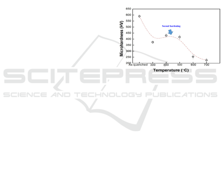
The hardness of the quenched and tempered
specimens is shown in Fig. 1. After quenching, the
specimen was hardened (~590 HV) by martensitic
transformation.The hardness decreased even
tempering at a low temperature (<300°C). But
whenthe tempering temperaturerose to 300°C (~375
HV), the hardness abruptlybecame harder. It showed
the steel was secondarily hardenedafter tempering at
300 ~ 500°C that the hardness abruptly increased.
When the steel was tempering ata higher
temperature like 600 ~ 700°C, the hardness of steel
decreased (~254 HV) at 600°C, and continuous
decreased (~225 HV) at 700°C.
Figure 1:Hardness test results of 13Cr MSS quenched and
tempering.
3.2 Effect of Heat Treatment on the
Microstructure of 13Cr MSS Steel
The OM microstructure of 13Cr MSS is shown in
Fig. 2.The martensitic of 13Cr MSS changes with
the tempering temperature rise. In the Martensitic
stainless steel after quenching and tempering, the
martensite decomposition, through the diffusion of
elements, grain boundary migration, the occurrence
of organizational changes (Caron R Net al.1972).
When the tempering temperature under 600°C, the
characteristics of martensite slabs are still evident in
Fig.2(a, b, c, d). As the temperature rise to 700°C,
the microstructure changes as fine ferrite with
carbides in Fig. 2(e).
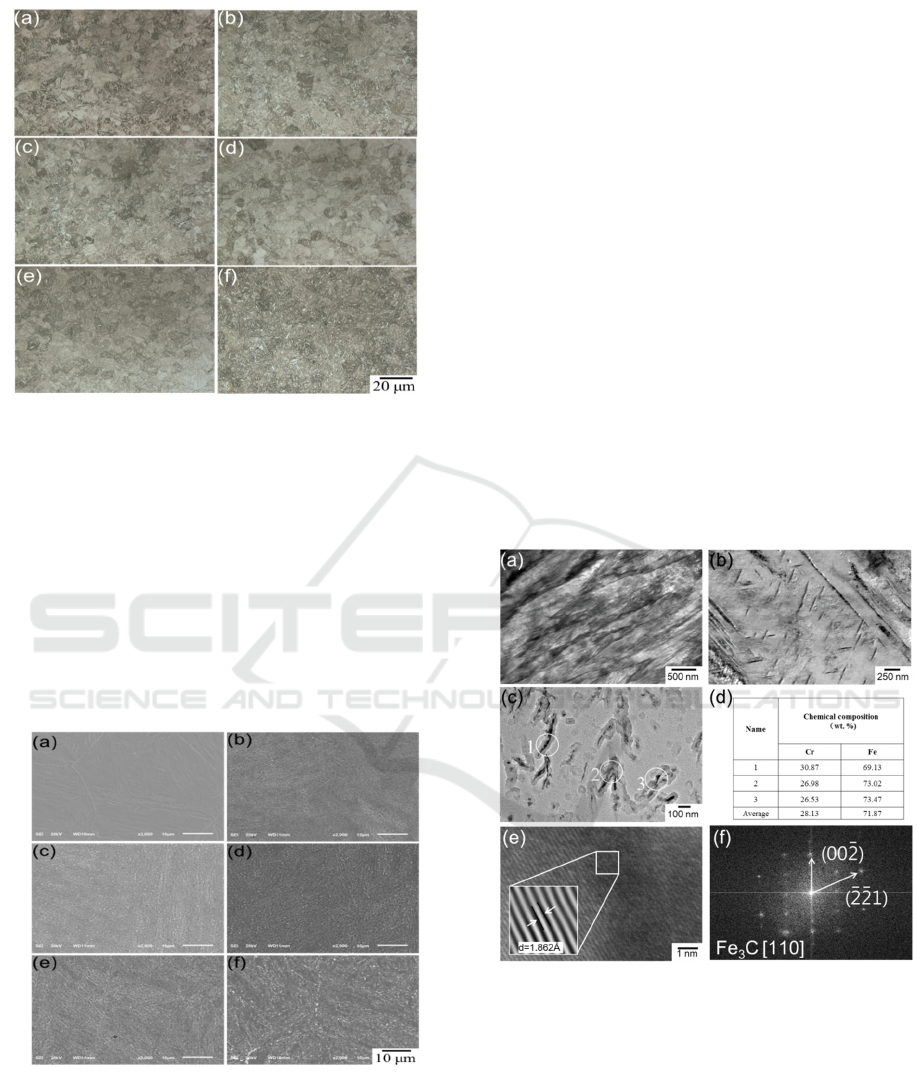
Figure 2:OM microstructures of 13Cr steel (a) quenched
at 1050°C tempered at (b) 300°C, (c) 400°C, (d) 500°C,
(e) 600°C, (f) 700°C for 2 hrs.
The SEM microstructure of 13Cr MSS is shown
in Fig. 3. Carbides are precipitated from the matrix.
With the increase of tempering temperature, the
matrix, the morphology and distribution of carbides
have changed. At a low tempering temperature, the
matrix of martensite coarsed in Fig.3(b, c), and at a
higher tempering temperature, the martensite matrix
began to disappear in Fig.3(d). As shown in
Fig.3(e,f),the martensite lath already disappeared,
and carbides have gathered to grow into sphere-like .
Figure 3 : SEM microstructures of 13Cr steel (a)
quenched at tempered at 1050°C tempered at (b) 300°C,
(c) 400°C, (d) 500°C, (e) 600°C, (f) 700°C for 2 hrs.
In order to judge the different carbides in 13Cr
MSS with tempering temperature rising. The TEM
samples were prepared with the 300°C, 500°C,
700°C tempering temperature. The TEM analysis
indicates that two processes can occur during
tempering: recovery and recrystallization of the
matrix and the precipitation of various carbides. The
TEM micrographs of 13Cr MSS tempered at 300°C
is shown in Fig. 4.
As shown in Fig. 4(a), the figure shows a
martensite lath area, composed of multiple slabs
single crystal, roughly parallel, the slab width,
length and length, the thickness of about tens of
nanometers to hundreds of nanometers, the existence
of slats dislocation substructures. The needle-like
carbides is shown in Fig. 4(b). To specifically
examine the formation of precipitates, a carbon
extraction replica was utilized to precisely identify
the carbides formed by tempering in Fig. 4(c).The
EDS, high-resolution TEM (HRTEM), fast Fourier
transformation (FFT) and the corresponding inverse
fast Fourier transformation (IFFT) has been
employed to identify the detailed information of
these carbides in Fig. 4(d, e, f).The orthorhombic
type Fe
3
C carbide was found in the specimen
tempered at 300°C.
Figure 4:TEM images of 13Cr steel tempered at 300°C
for 2 hrs: (a) matrix, (b) carbides in matrix, (c)carbides
analysis by carbon extraction replica technology, (d) EDS
results from (c) carbides, (e) HR-TEM images of carbides,
(f)The FFT pattern from (e), and inset of (e) shows the
IFFT image.
The TEM micrographs of 13Cr MSS tempered at
500°C is shown in Fig. 5. The martensite lath
coarsed in Fig. 5(a). The needle-like carbides
coarsed in Fig. 5(b,c). The EDS results show the
Fe3C carbides increase with the tempering
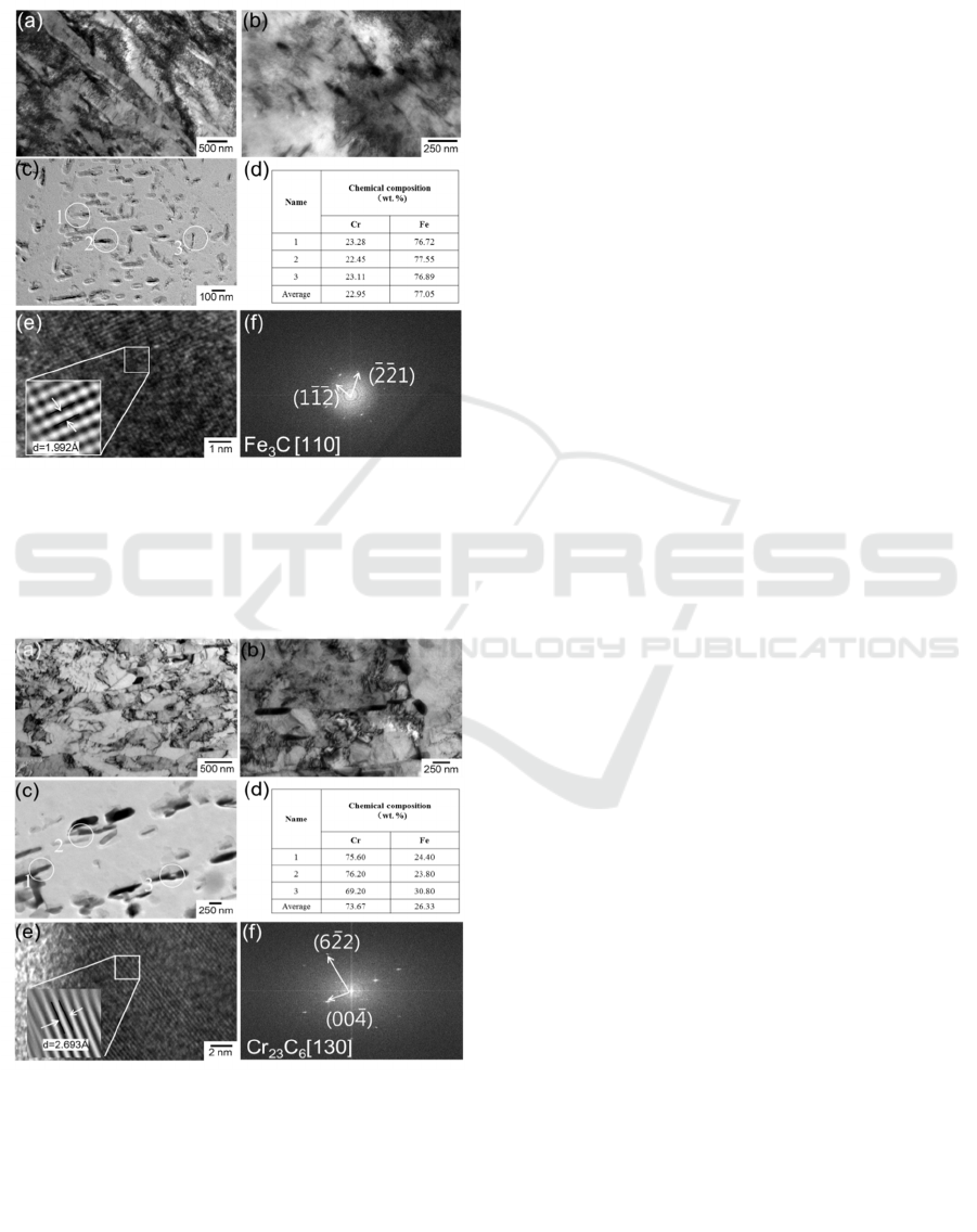
temperature in Fig. 4(d) and Fig. 5(d). The HRTEM,
the FFT pattern and the inverse FFT pattern shows
that it is also Fe3C carbide when tempering at 500°C
in Fig. 5(e, f).
Figure 5: TEM images of 13Cr steel tempered at 500°C
for 2 hrs: (a) matrix, (b) carbides in matrix, (c)carbides
analysis by carbon extraction replica technology, (d) EDS
results from (c) carbides, (e) HR-TEM images of carbides,
(f)The FFT pattern from (e), and inset of (e) shows the
IFFT image.
Fig. 6. TEM images of 13Cr steel tempered at 700°C for 2
hrs: (a) matrix, (b) carbides in matrix, (c)carbides analysis
by carbon extraction replica technology, (d) EDS results
from (c) carbides, (e) HR-TEM images of carbides, (f)The
FFT pattern from (e), and inset of (e) shows the IFFT
image.
The TEM micrographs of 13Cr MSS tempered at
700°C is shown in Fig. 6. After tempering at 700°C,
recovery and recrystallization of the matrix is shown
in Fig.6(a). The rod-like Cr-rich carbides was found
in original martensite lath and sphere-like Cr-rich
carbides was found in original austenite grain
boundary in Fig. 6(b, c). The EDS results, HRTEM
image analysis, fast Fourier transformation (FFT)
and the corresponding inverse fast Fourier
transformation (IFFT) indicates that these carbides is
Cr
23
C
6
carbide in 13Cr MSS when tempering at
700°C in Fig. 6(d, e, f).
4 CONCLUSIONS
During tempering, the matrix recovery by the
migration of lath boundaries and annihilation of
dislocations to slightly coarsen the lath and decrease
the dislocation density at temperatures lower than
500°C, and the formation of fine ferrite grains and
subsequent grain growth during tempering at
temperatures at 700°C to replace the original lath
structure.
Two types of Fe
3
C and Cr
23
C
6
carbides
precipitation are suggested. The needle-like
precipitation of Fe
3
C in lath martensite occurs at 300
~ 500°C. As the tempering temperature increased
(700°C), the phase transformation of Fe
3
C carbides
to Cr23C6 carbides occurred. The Cr
23
C
6
carbides
precipitation along the martensite lath is rod-like and
precipitation along grain boundaries is sphere-like.
Precipitation of Fe3C carbides at low
temperature enhances the hardness of the steel upon
precipitation hardening. As the tempering
temperature increased, the steels were dramatically
softened by grain growth and recrystallization.
REFERENCES
1. Feng Z. et al.2016.Analysis of Pitting Corrosion on
N80 3Cr Anti-corrosion Casing. Steel Pipe. 45(5),
p.60-63.
2. Jianqiang Y. et al. 2015. Selection and evaluation
methods of casing and tubing materials for sour
environments. Chemical engineering of oil & gas.
44(3). p.70-73.
3. CabelloG.et al. 2013.CO and trans-cinnamaldehyde as
corrosion inhibitors of I825, L80-13Cr and N80 alloys
in concentrated HCl solutions at high pressure and
temperature. ElectrochemicalActa. 97(5). p.1-9.
4. Sidorin D. et al. 2005. The electrochemistry of 13%
chromium stainless steel in oilfield brines.

ElectrochemicalActa. 50(20). p.4109-4116.
5. Larsen J. et al. 2015. Effect of Intervention History on
Corrosion State of Production Tubulars. Heat
Treatment of Metals. 34(1). p.75-77.
6. IsfahanyA N. et al. 2015.The effect of heat treatment
on mechanical properties and corrosion behavior of
AISI420 martensitic stainless steel. Journal of Alloys
& Compounds. 509(9). p.3931-3936.
7. Chakraborty G. et al. 2015. Study on tempering
behaviour of AISI 410 stainless steel. Materials
Characterization. 100. p.81-87.
8. Pfennig A. et al. 2013. Corrosion and corrosion fatigue
of AISI 420C (X46Cr13) at 60 °C in CO 2 -saturated
artificial geothermal brine. Corrosion Science. 68.
p.134-143.
9. Caron R N. &Krauss G. 1972. The tempering of Fe-C
lath martensite. Metallurgical and Materials
Transactions B. 3(9). p.2381-23
