
Analysis of Bolts’ Axial Corrosion Using Guided Waves
Based on FEM
P Ding
1,2, *
C Lu
3
, G F Ma
1
, T Li
1
, G F Yue
1
and X L Huang
1
1
Standard & Quality Control Research Institute Ministry of Water Resources. P.R.C,
Hangzhou, China
2
Key Laboratory of Research on Hydraulic and Hydro-Power Equipment Surface
Engineering Technology of Zhejiang Province, Hangzhou, China
3
Key Lab of Nondestructive Testing, Ministry of Education, Nanchang Hangkong
University, Nanchang, China
Corresponding author and e-mail: P Ding, qddp2008@126.com
Abstract. Bolts are widely used in water conservancy and hydropower engineering. There are
no good methods to test the corrosion defect of the bolts. Guided wave was used in this paper
to test the simulation axial defect in bolt based on FEM. The trend of the axial corrosion
coefficient and reflection coefficient of the guided wave was revelled. It shows that the
change trend of the defect reflection and wave type conversion of L (0, 1) mode and F (1, 1)
mode is consistent. The defect reflection of F (1, 1) is higher than the defect reflection of L (0,
1), both the defect reflection of F (1, 1) and L (0, 1) are no higher than 25%. And also it
verified the capability of low-frequency guided wave in detecting the small and medium
defects of bolts’ corrosion.
1. Introduction
Hydropower project transmission tower is an important facility to erect high-voltage transmission
lines. It is important to keep the tower fastness and reliable. The bolt is significant structure of
transmission tower, the safety and stability of bolt is in a very great degree affect the safety, stability
and service life of the transmission tower. Since the 1950s, China started using anchor in the coal
mine. And as support structure the anchor is widely used in the rock. With the development of
hydropower industry and the demand of the long-distance transmission, a large number of bolts have
been used in the cable of power transmission tower. These bolts are main load-bearing members,
which bear a large force and are used in bad environment. During the long term use, the effects of
cutting, fatigue and rainwater corrosion and the potential defects in the construction process easily
cause the failure, resulting in the occurrence of the accident. Not only does it cause enormous
economic losses, but it also results in casualties. Therefore, it is very important to use nondestructive
testing method to evaluate the operation condition and corrosion state of transmission tower. Guided
wave is a kind of ultrasonic wave which can be propagated in plates, rods and tubes, with the
advantages of small attenuation and long propagation distance. It has natural advantages for the
detection of transmission tower bolts defects such as rust.
616
Ding, P., Lu, C., Ma, G., Li, T., Yue, G. and Huang, X.
Analysis of Bolts’ Axial Corrosion Using Guided Waves Based on FEM.
In Proceedings of the International Workshop on Materials, Chemistry and Engineering (IWMCE 2018), pages 616-620
ISBN: 978-989-758-346-9
Copyright © 2018 by SCITEPRESS – Science and Technology Publications, Lda. All r ights reserved
2. Guided waves in bolt
The ultrasonic guided wave is caused by wave interference and dispersion due to multiple reflection
and scattering in the boundary of the propagation medium. The phase velocity is the rate at which the
phase of the wave propagates in space. This is the velocity at which the phase of any one frequency
component of the wave travels. The group velocity of a wave is the velocity with which the overall
shape of the wave's amplitudes-known as the modulation or envelope of the wave—propagates
through space. Guided waves are propagated by group velocity, and it have two characteristics:
dispersion characteristics and multimodal characteristics [1-7].
There are three modes of the ultrasonic wave propagating along the axial direction in the bolts, the
longitudinal axisymmetric mode L (0, m), the torsional mode T (0, m) and bending mode F (n,m).
The same frequency corresponds to several wave Numbers, that is, there are several different modes
at a certain frequency, and as the frequency increases, the number of modes becomes more and more.
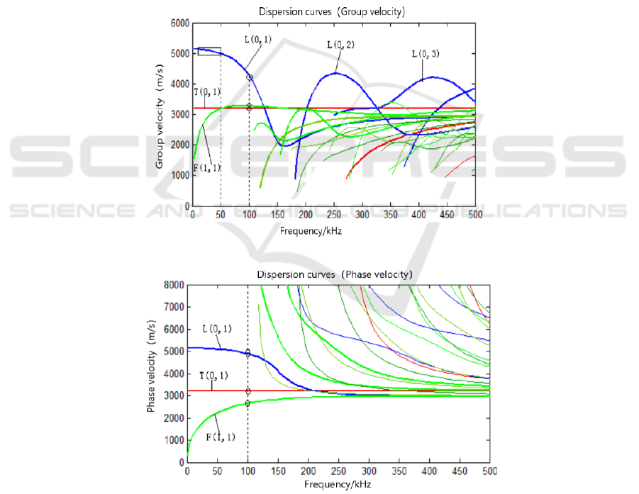
Theoretically, in the low frequency range (< 100kHz) only exist L (0, 1) and F (1, 1) mode, and the
velocities of this two modes are quite different. The dispersion curve in theoretical draw by matlab of
a solid cylinder with a diameter of 20mm and a length of 2m is shown in Figure 1.
(a) Dispersion curve of group velocity
(b) Dispersion curve of phase velocity
Figure 1. Dispersion curve of the solid cylinder with a diameter of 20mm and a length of 2m.
From the dispersion curve, it approves that when the frequency < 100kHz, there are only two
modes: the longitudinal mode L (0, 1) and the bending mode F (1, 1). So L (0, 1) mode and F (1, 1)
Analysis of Bolts’ Axial Corrosion Using Guided Waves Based on FEM
617
mode are selected to detect the corrosion of the bolts in order to avoid the other modes mask the
defect echo.
3. Simulation Model
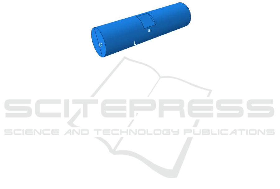
According to the bolts’ size, the model is shown in Figure 2. In this model D=20mm, L=2m. The
length of the defect axis is indicated by a, and the axial corrosion coefficient (A) is defined as the
percentage of defect length(a) and wavelength. Reflection coefficient of ultrasonic guided wave R is
defined as R=B(ω)/A(ω), In this paper, B(ω) is the amplitude spectrum of the waveguide wave echo
at the end surface or the defect, A(ω) is the amplitude spectrum of the excitation signal wave. The
greater R is and the greater of the energy of reflected echo signal will be.
Figure 2. Bolt’s Model.
The material properties of the bolt are: Young’s Modulus E=206000Mpa; Poisson’s Ratio σ=0.30;
Mass Density ρ=7580kg/m3. ABAQUS/Explicit dynamic module was adopted in the simulation, and
the grid cell type was selected as C3D4, the length of the elements was set as 1/20 of the wavelength.
According to theory and simulation, guided wave excitation and acceptance point are set at the end
surface, and the waveguide frequency is 50kHz.
4. Result and Discussion
The defect depth is 1mm and distribution along the circumference, the axial length corrosion
coefficient(A) is 10%, 20%, 30%...90 percent to simulate. The results were shown from Figure 3 to
Figure 11.
From Figure 3 - Figure 11, it shows that the change of axial length coefficient is related to the
defect reflection coefficient. When axial length greater than or equal to 50%, the last time become
longer both the defect reflection L (0, 1) and wave type conversion F (1, 1). The transformation wave
pattern increases with the increase of axial length coefficient because that as the axial length
increases, the front and rear surfaces of the defect position are all reflected. Figure 12 shows the
relationship between the axial corrosion coefficient (A) and reflection coefficient (R). The change
trend of the defect reflection and wave type conversion of L (0, 1) mode and F (1, 1) mode is
consistent. The defect reflection of F (1, 1) is higher than the defect reflection of L (0, 1) mode, both
the defection of F (1, 1) and L (0, 1) are no higher than 25%.
IWMCE 2018 - International Workshop on Materials, Chemistry and Engineering
618
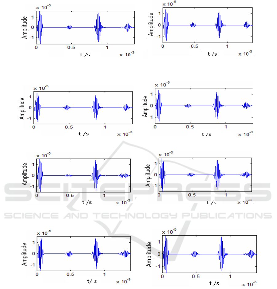
Figure 3. Waveform of A=10%. Figure 4. Waveform of A=20%.
Figure 5. Waveform of A=30%. Figure 6. Waveform of A=40%.
Figure 7. Waveform of A=50%. Figure 8. Waveform of A=60%.
Figure 9. Waveform of A=70%. Figure 10. Waveform of A=80%.
Analysis of Bolts’ Axial Corrosion Using Guided Waves Based on FEM
619
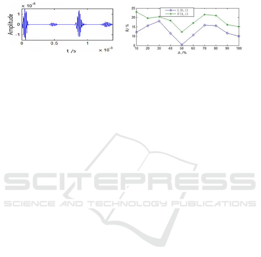
Figure11. Waveform of A=90%.
Figure 12. Trend of the Axial corrosion
coefficient and Reflection coefficient.
5. Summary
Through numerical simulation, the capability of low - frequency guided wave in detecting the small -
and - medium defects is verified. The reflection coefficient changes with the change of axial defect,
and it has good correspondence which provides a good reference for the guide wave detection of bolt
and other long straight bars, which are used in water conservancy and hydropower engineering.
Through further research and experiment, it is beneficial to the development of water conservancy
and hydropower engineering guided wave detection.
Acknowledgement
Thanks to the support of Science and Technology Project of Zhejiang Province (Nos. 2017C37062).
References
[1] Zeng G P 2017 Study on propagation characteristics of ultrasonic guided waves in arch
bridge suspender Zhejiang University.
[2] Rose J L 1999 Ultrasonic waves in solid Media Cambridge University Press
[3] Gazis D C 1959 Three dimensional investigation of the propagation of waves in hollow
circular cylinders Analytical Foundation J. of the Acoustics Society of America 31 pp568-
573
[4] Menachem Z and Tapuchi S 2013 Analyzing wave propagation in helical waveguides using
laplace, fourier, and their inverse transforms, and applications Intech: Wave Propagation
Theories and Applications
[5] Ahmed S R and Saka M 2000 A new ultrasonic angle-beam technique for sensitive evaluation
of closed cracks NDT&E International 33(4) pp 261-271
[6] Yang H 2013 Research on using ultrasonic guided wave NDT technique to detect the quality of
metal buffer rod cofferdam system North University of China
[7] Ivanovic A, Neilson R D and Rodger A A 2001 Numerical Modeling of single tendon ground
anchorage systems Geotech. Eng.142(2) pp 103-113
IWMCE 2018 - International Workshop on Materials, Chemistry and Engineering
620
