
Effects of Stress and Roughness on the Reflectivity of Blue
Light in ZnS/MgF
2
Multilayers
S Y Lian
1
, S H Xiao
1
, Y P Yu
1
, S H Lin
1
, H Y Zhang
2
, G Lin
2
, C K Xu
3
and J Y
Wang
1,
*
1
Department of Physics, Shantou University, Shantou, 515063, Guangdong, China
2
ShanTou Go World-Display Co. LTD, Shantou, 515065, Guangdong, China
3
Wuxi Xumatic Co., Ltd., Wuxi, 224200, Jiangsu, China
Corresponding author and e-mail: J Y Wang, wangjy@stu.edu.cn
Abstract. The influences of stress and interface roughness on the reflectivity of blue light in
the ZnS/MgF
2
multilayered film are evaluated quantitatively using the small deflection theory
of elastic mechanics and the index method. The simulated results show that upon the interface
roughness increasing, the reflectivity value of the blue light decreases but the shape of the
reflectivity curve does not change. The applied stresses do not change the shape of the
reflectivity curve. Depending on the compressive or tensile stress, the respective reflectivity
curve shifts to right or left as compared to the one without stress, but such a shift depends
strongly on the substrate thickness.
1. Introduction
The blue light that is part of the white light do have great harm to the human eye by damaging the
light-sensing cells of retina [1]. Many efforts have been made to design a suitable optical
multilayered film for filtering the blue light. To this end, the reflectivity of blue light in the prepared
multilayered film is often evaluated quantitatively in order to obtain an optimum layered structure.
On the other hand, to prepare a multilayered film on a foreign substrate, the interface roughness
between sublayers and the stress between film and substrate may be introduced into the multilayered
structure. Therefore, the effects of stress and interface roughness on the reflectivity of blue light in
the multilayered structure have to be taken into account in order to obtain a reliable simulated result.
It was found that the interface roughness has a significant influence on the reflectivity by
scattering losses, which has already been treated successfully both in theory and experiment [2].
Many papers in literature report the roughness effect on the optical properties for single layered
structure [3] and for multilayered structure. Stress in thin film associated with the lattice mismatch
and the difference of thermal expansion coefficient between film and substrate has also an impact on
the reflectivity of optical thin film [4-5]. The stress may cause film crack and even falling off
degrading the stability and the reliability of optical thin film. Currently, a couple of models have been
put forward for analyzing the stress [6-11] such as the finite element method [12-14] and the
boundary element method [15-16]. The stress in thin film is usually characterized by the curvature
method [17].
In this paper, the influences of stress and interface roughness on the reflectivity of the blue light in
478
Lian, S., Xiao, S., Yu, Y., Lin, S., Zhang, H., Lin, G., Xu, C. and Wang, J.
Effects of Stress and Roughness on the Reflectivity of Blue Light in ZnS/MgF2 Multilayers.
In Proceedings of the International Workshop on Materials, Chemistry and Engineering (IWMCE 2018), pages 478-485
ISBN: 978-989-758-346-9
Copyright © 2018 by SCITEPRESS – Science and Technology Publications, Lda. All rights reserved
the ZnS/MgF
2
multilayered film will be evaluated quantitatively using the index method and the
small deflection theory of elastic mechanics. The zinc sulfide and magnesium fluoride are chosen
because of the larger difference in their refractive index values.
2. Influence of interface roughness on the reflectivity
To simulate the reflectivity of an optical multilayered structure, a recursive method is often applied
using an equivalent interface [18].
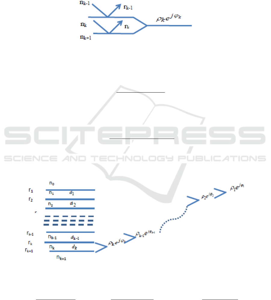
Figure 1. The equivalent interface of a single layer.
For a single layer, the equivalent interface is shown in Figure 1 and the corresponding reflection
coefficient of this single layer is given by
k
k
k
j
kk
j
kk
i
err
err
er
δ
δ
ϕ
ρ
2
1
2
1
k
1
−
+
−
+
+
+
==
(1)
where r
k
is reflection coefficient of the upper interface, r
k+1
is reflection coefficient of the lower
interface. The r
k
can be obtained by the Fresnel expression for S polarization as
tkik
tkik
k
nn
nn
r
θθ
θθ
coscos
coscos
1
1
+
+
+
−
=
(2)
where
θ
i
is the incident angle,
θ
t
is the refracted angle. According to the Snell’s law
(
sskk
nnn
θθθ
sinsinsin
00
==
), the incident angle or the refracted angle can be calculated.
n
k
is
the refractive index of the
k-th
layer.
Figure 2. The recursive method for obtaining the Fresnel coefficient.
For a multilayered structure as sketched in the left side of figure 2, the equivalent interfaces are
constructed as shown in the right side of Figure 2.
k
k
k
j
kk
j
kk
i
err
err
e
δ
δ
ϕ
ρ
2
1
2
1
k
1
−
+
−
+
+
+
=
1-
1-
1-
2
1-
2
1-
1-k
1
k
k
k
j
kk
j
kk
i
er
er
e
δ
δ
ϕ
ρ
ρ
ρ
−
−
+
+
=
......
1
1
1
2
21
2
21
1
1
δ
δ
ϕ
ρ
ρ
ρ
j
j
i
er
er
e
−
−
+
+
=
(3)
Effects of Stress and Roughness on the Reflectivity of Blue Light in ZnS/MgF2 Multilayers
479

where
jjjj
dn
θ
λ
π
δ
cos
2
=
and
d
j
are the phase difference and the thickness of the
j-th
layer,
respectively,
λ
represents the wavelength of incident light.
Then, the reflectivity of the multilayer can be calculated by
∗
⋅= rrR
(4)
To calculate the refraction index, the Sellmeier dispersion equation of equation (5) is used
()
2
2
λ
λ
B
An +=
(5)
where, for the investigated material MgF
2
, A=1.8976, B=0.01536 and for ZnS, A=5.013, B=0.2025.
When considering the effect of the interface roughness on the reflectivity of optical multilayers,
two methods may be applied: the stratified-interface method [19] and the index method [20]. In the
stratified-interface method, the rough interface is divided into different uniform thin layers, each
layer has a homogeneous interface. As long as the divided layer is thin enough, the
stratified-interface method can be used to describe well a rough continuous interface [19]. The index
method is to calculate the Fresnel reflection coefficient at each interface where the interface
roughness parameter is characterized by the real-structure model [21] and the Nevot-Croce model
[20].
In the index method, the reflection coefficient at each interface of a multilayered structure is given
by [20]
() ()
qMrqrr
jj 0
2
0
2
1
exp =
⎥
⎦
⎤
⎢
⎣
⎡
−=
σ
(6)
where
j
q
θ
λ
π
cos
4
=
,
()
qM
j
is called the Debye Waller factor, σ represents the interface roughness,
θ
j
is the incident angle,
r
0
is the Fresnel reflection of the perfect interface (
σ
= 0). This method is
applied to the case that the wavelength of the incident light is much large than the interface roughness
[22-23]. For considering the influence of interface roughness on the reflectivity, the equation (2) will
be replaced by the equation (6).
In the Real-Structure model [21], the interface roughness parameter is assumed to be increased
with the depth from the substrate to the surface as demonstrated in Figure 3.
Figure 3. The sketch of the divided
multilayer interfaces with different
roughness characteristics.
The j-th interface roughness between the j-th and (j +1)-th sublayers is assumed as [22]
()
jkkj
zzh −+=
++ 1
2
1
σσ
(7)
where
σ
k+1
is the surface roughness of the substrate, z
k+1
and z
j
represent, respectively, the coordinate
IWMCE 2018 - International Workshop on Materials, Chemistry and Engineering
480

values of the substrate’s surface and the j-th sublayer’s surface as shown in figure 3, h is a constant
defined as the increase rate of interface roughness.
The factor Mj (q) is given by
⎥
⎥
⎦
⎤
⎢
⎢
⎣
⎡
⎟
⎟
⎠
⎞
⎜
⎜
⎝
⎛
−=
+1
2
coscos
4
2
1
exp
jj
j
j
M
θθ
λ
πσ
(8)
For h = 0 and
σ
k+1
= 0, it corresponds to an ideal interface.
3. Stress characterization
Due to the lattice mismatch between the film and the substrate, the film is constrained as shown in
Figure 4.
Figure 4. The sketch of the constrained
film with the substrate. t
f
is the film
thickness, t
s
is the thickness of the
substrate. The middle plane of the
substrate indicated as dashed line as no
stress plane.
Assumed that t
s
is much larger than t
f
, and the stress in the film is regarded as a uniform
distribution, the Stoney equation is expressed as [20]
f
s
s
s
f
Ct
tE
61
2
⎟
⎟
⎠
⎞
⎜
⎜
⎝
⎛
−
=
ν
τ
(9)
where τ
f
is the stress of surface, and C is the radius of curvature. In the z plane, the strain of xy plane
is proportional to the distance z. Assuming that the Poisson's ratios of the film and the substrate are
equal, namely, ν
s
= ν
s
= 0.25. While, for the glass substrate, the Es is equal to 55GPa. The packaging
density P [24] is then described as
()
1
0
421
−
−+= kZkZPP
ν
(10)
where k=1/C. Upon the curvature change, the refractive index can be rewritten as
()()
1421421
11
0
+−+−−+=
−−
kZkZkZkZnn
νν
(11)
where n
0
is the refractive index of thin film material without stress. The equation (11) shows that the
refractive index is associated with the distance Z from the middle plane of the substrate to the
interface. Assuming that the substrate thickness is greater than that of the film and the refractive
index of each sublayer is regarded as the same. Applying the equation (6) and (11) into the equation
(2), the reflected coefficient of the multilayer can be calculated for considering the influences of both
interface roughness and stress on the reflectivity.
4. Result and discussion
For the investigated refractive index materials, zinc sulfide and magnesium fluoride, using the
Effects of Stress and Roughness on the Reflectivity of Blue Light in ZnS/MgF2 Multilayers
481
Genetic algorithm and truncation selection strategy, the optimum 4x ZnS/MgF
2
multilayered
structure for the anti-reflectivity of the blue light is determined as 149, 29, 74, 31, 80, 33, 249 and
127 nm thick, respectively. In the following, the reflectivity of the above optimum multilayered
structure will be calculated assuming that the incident light is perpendicular to the surface/interface,
i.e.
θ
0
= 0.
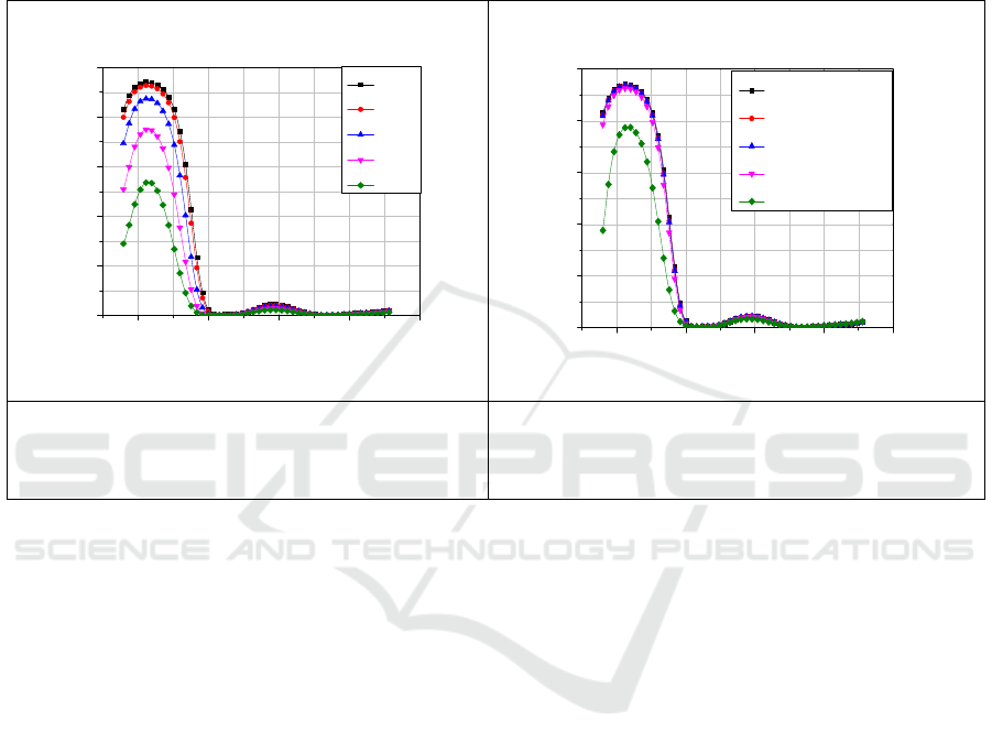
4.1. Effect of roughness
400 500 600 700 800
0.0
0.2
0.4
0.6
0.8
1.0
Reflectivity
Wavelength/nm
σ=0
σ=10
σ=20
σ=30
σ=40
400 500 600 700 800
0.0
0.2
0.4
0.6
0.8
1.0
Reflectivity
Wavelen
g
th/nm
No Roughness
h=0.002
h=0.02
h=0.2
h=2
Figure 5. The reflectivity for different
substrate roughness values with the same h
value of 0.002.
Figure 6. The reflectivity for the different h
values with the same substrate roughness of
5nm.
Figure 5 shows that, with increasing the substrate roughness for the same h value of 0.002, the
reflectivity of this multilayer is reduced. When the substrate roughness is less than 10 nm, the effect
of roughness on the reflectivity can be ignored. However, when the substrate roughness is more than
40 nm, the maximum value of the reflectivity of the blue light is dropped significantly about 39% as
compared to the ones for the roughness less than 10 nm. Upon the interface roughness increasing, the
reflectivity value of the blue light decreases but the shape of the reflectivity curve does not change.
Figure 6 shows that, for the substrate roughness of 5 nm, the maximum reflectivity value
decreases gradually with increasing of h value (the increase rate of interface roughness). But the
interface roughness does not affect the reflectivity curve when the h value is less than 0.2. However,
when the h value is of 2, the maximum reflectivity reduces about 15% but the shape of reflectivity
curve does not change.
IWMCE 2018 - International Workshop on Materials, Chemistry and Engineering
482
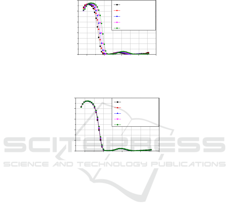
4.2. Effect of stress
400 500 600 700 800
0.0
0.2
0.4
0.6
0.8
1.0
Reflectivity
Wavelen
g
th/nm
stress=200GPa
stress=100GPa
stress=0GPa
stress=-100GPa
stress=-200GPa
Figure 7. The reflectivity for different stress values with the same glass substrate thickness of 0.1
mm.
400 500 600 700 800
0.0
0.2
0.4
0.6
0.8
1.0
Reflectivity
Wavelen
g
th/nm
stress=200GPa
stress=100GPa
stress=0GPa
stress=-100GPa
stress=-200GPa
Figure 8. The reflectivity for different stress values with the substrate thickness of 1 mm.
In practice, stress value generally will not more than a few Gpa. The stress value here was set to
200 Gpa to show the impact of stress on the spectrum value. Figure 7 shows, when the glass substrate
thickness is of 0.1 mm (the corresponding Young's modulus is 55 Gpa and the Poisson's ratio is 0.25),
upon increasing the compressive or tensile stress value, the respective reflectivity curve shifts to the
right or left as compared to the one without applied stress, but the shape the reflectivity curve
remains the same.
However, when the substrate thickness increases to 1 mm, and all the other parameters including
the applied stress values as indicated in Figure 7 remain the same, the reflectivity curve shown in
Figure 8 does not change at all. It concludes that the influence of the applied stress on the reflectivity
strongly depends on the substrate thickness. If the substrate thickness is thick enough, the applied
stress in the multilayered film has no significant influence on the reflectivity of the blue light.
5. Conclusions
(1) Upon increasing the interface roughness, the reflectivity value of the blue light decreases, but
the shape of reflectivity curve does not change;
(2) With increasing of the stress, the reflectivity curve shifts to the right or left as compared to the
one without applied stress, but the shape of reflectivity does not change;
(3)The effect of stress on the reflectivity of the blue light could be ignored when the substrate
thickness is thick enough.
Effects of Stress and Roughness on the Reflectivity of Blue Light in ZnS/MgF2 Multilayers
483

Acknowledgement
The authors gratefully thank the support of Science and Technology Planning Project of GuangDong
Province, China (Grant NO.2017A010103021).
References
[1] Keller C, Grimm C, Wenzel A, Hafezi F and Reme C 2001 Protective effect of halothane
anesthesia on retinal light damage:inhibition of metabolic rhodopsin regeneration Invest
Opthalmol Vis Sc. 42 475-480
[2] Carniglia C K 1979 Scalar scattering theory for multilayer optical coatings Opt. Engin. 18
104-115
[3] Ferre-Borrull J, Duparre A and Quesnel E 2000 Roughness and light scattering of
ion-beam-sputtered fluoride coatings for 193 nm Appl. Optics 39 5854-5864
[4] Whitman C S and Chung Y W 1991 Thermomechanically induced voiding of Al-Cu thin films
J. Vac. Sci. Technol. A9 2516-2522
[5] Windischmann H 1992 Intrinsic stress in sputter-deposited thin films Crit. Rev. Solid State 17
547-596
[6] Kinosita K, Maki K, Nakamizo K and Takeuchi K 1967 Stress in vacuum deposited films of
silver Jpn. J. Appl. Phys. 6 42-53
[7] Klokholm E and Berry B S 1968 Intrinsic stress in evaporated metal films J. Electrochem. Soc.
115 823-826.
[8] Hoffman R W 1976 Stresses in thin films: the relevance of gain boundaries and impurities
Thin Solid Films 34 185-190
[9] Alexander P M and Hoffman R W 1976 Effect of impurities on intrinsic stress in thin Ni film
J. Vac. Sci. Tech. 13 96-98
[10] Heurle F M D 2008 Aluminum films deposited by RF sputtering Metal. Mater. Trans. B 1
725-732.
[11] Muller K H 1987 Stress and microstructure of sputter deposited thin films: molecular
dynamics investigation J. Appl. Phys. 62 1796-1799
[12] Ward D J and Arnell R D 2002 Finite element modeling of stress development during
deposition of ion assisted coating Thin Solid Films 420-421 269-274
[13] Souza R M, Mustoe G G W and Moore J J 1999 Finite element modeling stress and fracture
during the indentation of hard elastic films on elastic-plastic aluminum substrate Thin Solid
Films 355-356 303-310
[14] Souza R M, Mustoeb G G and Moore J J 2001 Finite element modeling of stresses, fracture
and delamination during the indentation of hard elastic films on elastic-plastic soft
substrates Thin Solid Films 392 65-74
[15] Luo J F, Liu Y J and Berger E J 2000 Interfacial stress analysis for multi-coating systems
using an advanced boundary element method Comput Mech. 24 448-455
[16] Luo J F, Liu Y J and Berger E J 1998 Analysis of two dimensional thin structures (from
micro-to-nano-scales) using the boundary element method Comput Mech. 22 404-412
[17] Tian M B and Liu D L 1991 Handbook of thin film science and technology (Beijng: China
Machine Press) p 144-146
[18] Rouard P 1937 Optical properties of very thin metallic films Annales de Physique 7 291
[19] Zhou X L and Chen S H 1995 Theoretical foundation of X-ray and neutron reflectometry Phys
Rep 257 223-348
[20] Nevot L and Croce P 1980 Caracterisation des surfaces par reflexion rasante de rayons X.
Application a l’etude du polissage de quelques verres silicates Rev Phys Appl. 15 761-779
[21] Pleshanov N K 2004 Algorithm for the real-structure design of neutron supermirrors Nuclear
Instruments and Methods in Physics Research A. 524 273-286
IWMCE 2018 - International Workshop on Materials, Chemistry and Engineering
484

[22] Marquart D W 1963 An algorithm for least-squares estimation of nonlinear parameters J. Soc.
Ind. Appl. Math. 11 431-441
[23] Bevington P R, Robinson D K, Blari J M, Mallinckrodt J and Mckay S 1993 Data reduction
and error analysis for the physical science Computer in Physics 7 415
[24] Rastogi R, Dharmadhikari V and Diebold A 1991 Stress variation with temperature/time and
its correlation to film structure and deposition parameters Journal of Vacuum Science and
Technology A 9 2453-2458
Effects of Stress and Roughness on the Reflectivity of Blue Light in ZnS/MgF2 Multilayers
485
