
Chemical Flooding Process Integration of Low Viscosity Loss
Points Injection Technology Research and Application
S G Zhu
1
, F S Wang
1
, D K Xu
1
, C J Liu
1
, Q Z Li
1
,X L Song
1
, Q Ma
1
, H C Li
1,*
, L
J Wang
1
, P Li
2
, P F Tang
3
and G L Gao
1
1
Production and Engineering Research Institute Daqing oilfield Limited liability
company, Daqing
2
No.4 Oil Production Plant of Daqing Oilfield Co. Ltd, Daqing
3
No.6 Oil Production Plant of Daqing Oilfield Co. Ltd, Daqing
Corresponding author and e-mail: H C Li, lihaicheng@petrochina.com.cn
Abstract. Injection technology for water flooding points exist at the polymer solution flowing
through the injection allocation generated when mechanical degradation,big viscosity loss
need to inject (over 30%) and low permeable reservoirs with low relative molecular mass of
polymer solution, in order to make sure no problem such as block reservoir.Chemical
flooding process is studied in the integration of hierarchical points injection
technology,designed the low viscosity loss high throttling pressure regulator, wide adjusting
range low molecular weight and regulator of the choke points and the whole process of the
integration of eccentric injection allocation, layered injection and dual regulation of relative
molecular mass.Hydraulic characteristics, laboratory test results show that within the scope of
the flow rate of 70 m
3
/d, viscosity loss rate has dropped from 30% to 10%, and separate
injection technology compatible with water flooding, injection string meet blank water
flooding, separate chemical flooding and subsequent water flooding process need, reduce the
investment and production cost, is the application of more than 3000 Wells.Field test results
show that 2-3 interval cast get success rate of 95.6%, a 95% success rate increase.Statistics a
layered polymer injection blocks, separate injection Wells using layer is 9.8% higher than
general Wells, the thickness of use increased by 10.3%.
1. Introduction
Daqing oilfield is a heterogeneous multi-layer sandstone oilfield with largely different permeability,
tertiary oil recovery technology has become an important means for its stable production. Practice
showed[1,2] that chemical flooding could increase crude oil recovery ratio by more than 20
percentage points compared with water flooding. At present, the oil production of chemical flooding
wells is close to 1/3 of total output. With the development of chemical flooding, the class II and III
reservoirs with big difference in permeability and large interlayer contradictions have gradually
become the main development objects. However, in order to alleviate the contradiction between
layers, the separate injection technology needs to be improved in the process of chemical flooding
medium injection. Because of the mechanical degradation of polymer solution by shearing, the
conventional water flooding injection allocator has serious degradation of polymer and large
Zhu, S., Wang, F., Xu, D., Liu, C., Li, Q., Song, X., Ma, Q., Li, H., Wang, L., Li, P., Tang, P. and Gao, G.
Chemical Flooding Process Integration of Low Viscosity Loss Points Injection Technology Research and Application.
In Proceedings of the International Workshop on Materials, Chemistry and Engineering (IWMCE 2018), pages 167-173
ISBN: 978-989-758-346-9
Copyright © 2018 by SCITEPRESS – Science and Technology Publications, Lda. All rights reserved
167
viscosity loss. It can`t be directly applied to separate injection of chemical flooding wells. In addition,
the replacement of separate injection pipe string in the process of water flooding changing to
chemical drive and chemical drive changing to subsequent water drive will result in increase in
production cost.
In order to resolve these problems, this paper studies the integrated injection technology with
separate layer and separate mass in the whole process of chemical flooding. Low viscosity loss and
high throttle pressure regulators, wide molecular weight range and low throttle regulators of separate
mass, and whole process integrated eccentric injection devices are designed. Double adjustment of
layered injection volume and relative molecular mass has been achieved. The separate injection
technology is fully compatible with the water drive process. The pipe column can meet the needs of
separate injection in the whole process, including the blank water drive, chemical flooding and
subsequent water flooding. And it will reduce the cost of investment and production. The integrated
injection technology with separate layer and separate mass in the whole process of chemical flooding
can greatly improve the adaptability of the process, saves the cost of investment, and has the
conditions of scale application, and can play an important role in the oil production.
2. Study on low viscosity loss and high throttle pressure regulator
2.1. Choking element with streamlined annular depressurizing channel structure
The flow passage of the polymer solution is composed of multistep equidistant streamline units of
choking element outer surface and inner wall of deviation hole of eccentric injection device. When
the polymer solution flows through the throttling unit of flow passage, the flow velocity is changed
by the change of the flow area. As the shear degradation rate of polymer solution is related to the
flow stability [3,4], easy to change of the flow field of polymer solution and easy to deform of the
polymer molecular chain lead to the shear degradation rate of polymer solution becoming faster. In
order to reduce shear degradation rate of the polymers, we designed choking element with
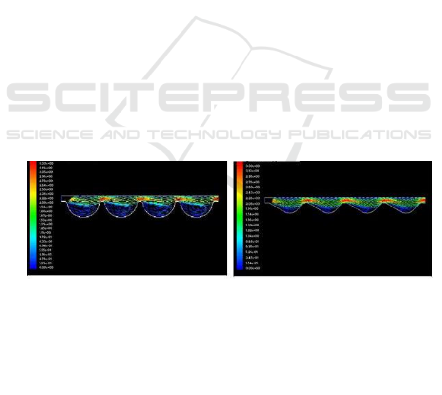
streamlined annular pumpdown channel structure. We got its velocity vector diagram by fluid
numerical simulation software, and compared it with velocity vector diagram of old semicircle
throttling device ,show in Figure 1, show in Figure 2.
Figure 1. Semicircle annular pumpdown unit. Figure 2. Streamlined annular pumpdown unit.
The results of analysis and calculation show that the pressure distribution of streamline
depressurization unit is more uniform than the semicircle depressurization unit, flow field trend is
stable, flow around is significantly lower than the latter, and turbulence is not prone; because of the
influence of flow around, backflow phenomenon of the semicircle depressurization unit is more
serious. Therefore, a streamline multistage pumpdown unit choking device is preferred. The device
of separable combination structure can be used in series for reducing the investment cost and
processing difficulty,show in Figure 3.
IWMCE 2018 - International Workshop on Materials, Chemistry and Engineering
168
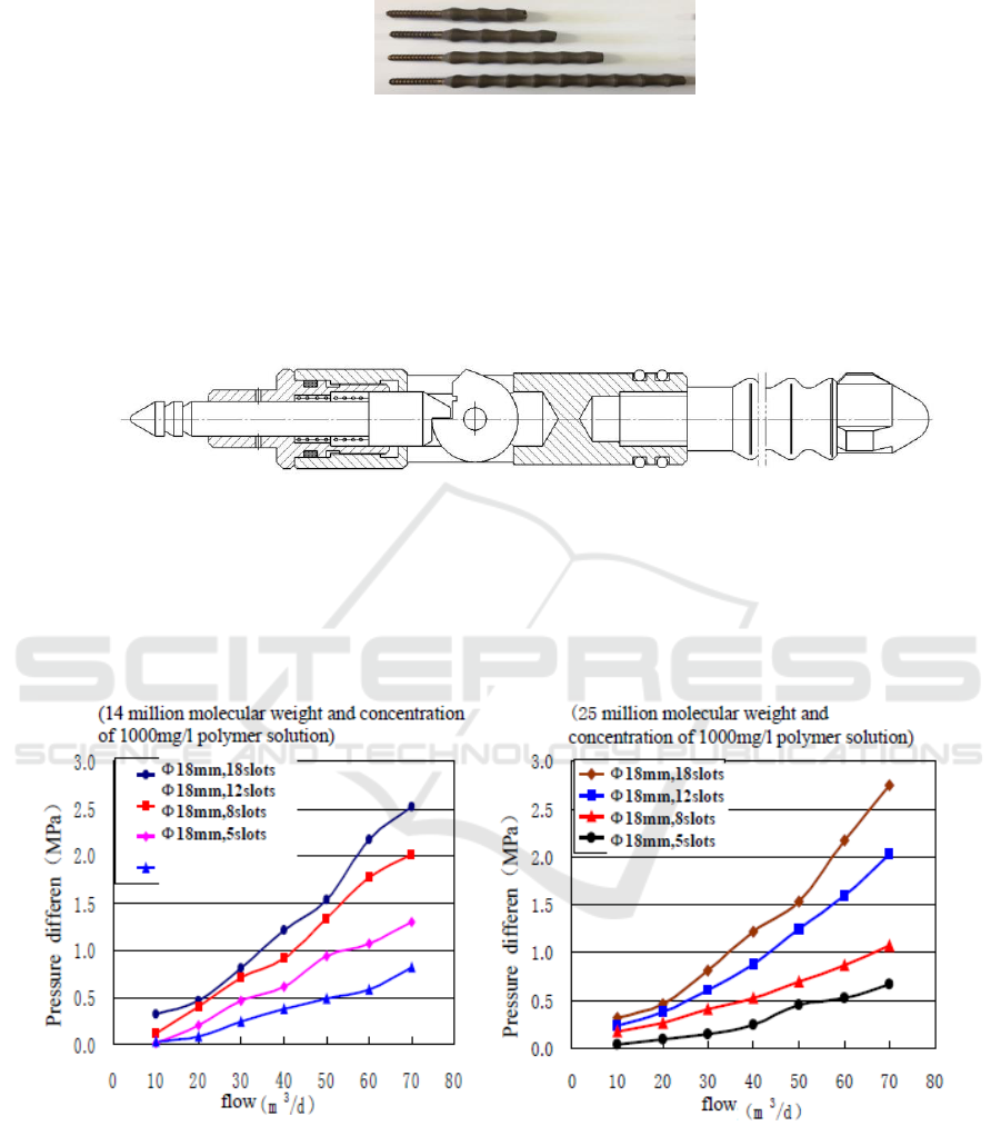
Figure 3. Physical map of separable combination pressure regulation device.
2.2. Pressure regulator of low viscosity loss and high throttle
A pressure regulator is composed of pressure regulating plugging device and whole process
integrated eccentric distributor,show in Figure 4. Injection pressure is controlled by throwing and
pulling the injection tools and changing number of slots of streamlined annular pumpdown unit, To
achieve the purpose of controlling injection volume of injection layer[5, 6].
Figure 4. Pressure regulating plug.
Performance indicators:
When the pressure regulator is in the range of 70m3/d flow, the maximum throttling pressure
difference is about 2.7MPa. The viscosity loss rate of polymer solution is less than 9.2%,show in
Figure,show in Figure 6
Figure 5. Contrast curve of pressure regulator
flow and throttle pressure difference.
Figure 6. Contrastcurve of pressure regulator
flow and throttle pressure difference.
3. Study on separate mass regulators with wide molecular weight range and low throttle
3.1. regulation mechanism of polymer molecular weight
The rheological property of polymer aqueous solution belongs to non Newtonian fluid, and it has
both viscous and elastic properties. From the microscopic point of view, polymer molecules are
Chemical Flooding Process Integration of Low Viscosity Loss Points Injection Technology Research and Application
169
distributed in aqueous solutions with particles, branched and reticular structures, and the molecular
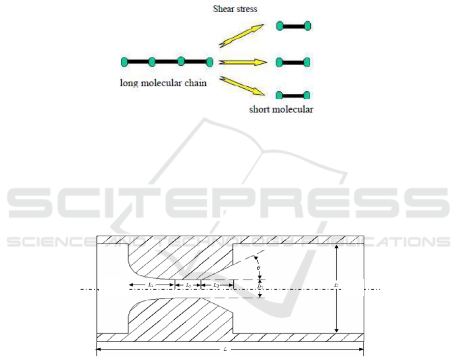
chains are flexible chain structure. The polymer molecules conformation will be changed by external
force. For example, when a coiled polymer chain is subjected to a certain stretching force, the
polymer chain will be stretched. When the external force is lost, it can recover the original state. But
when the force exceeds the critical value (such as the mutation of polymer solution rate), the polymer
chain will break, and this will result in the irreversibility of recovery. Mechanical degradation caused
molecular chains to decompose and break, changed the shape and size of polymer molecules, so
these resulted in the decrease of polymer molecular weight [7]. show in Figure 7
Figure 7. Diagram of shearing polymer Molecular weight.
3.2. regulating element of Molecular weight
According to the above principle of mechanical degradation, we designed a "hyperbolic + trapezoidal
mouth" type molecular weight regulating element,show in Figure 8. The degradation strength of
polymers can be controlled by changing the nozzle diameter, so as to achieve the purpose of
adjusting the molecular weight of polymer(The nozzle is made from ceramic material, Diameter 2.0-
6.0mm, Increasing at intervals of 0.2mm).
Figure 8. Structure schematic of "hyperbolic + trapezoidal mouth" type molecular weight regulating
element.
3.3. Molecular weight regulating plug
A molecular weight regulator is composed of pressure regulating plugging device and whole process
integrated eccentric distributor,show in Figure 9. Molecular weight degradation rate is controlled by
throwing and pulling and changing the nozzle diameter, so as to achieve the purpose of adjusting the
molecular weight of polymers.
exit
porch
IWMCE 2018 - International Workshop on Materials, Chemistry and Engineering
170
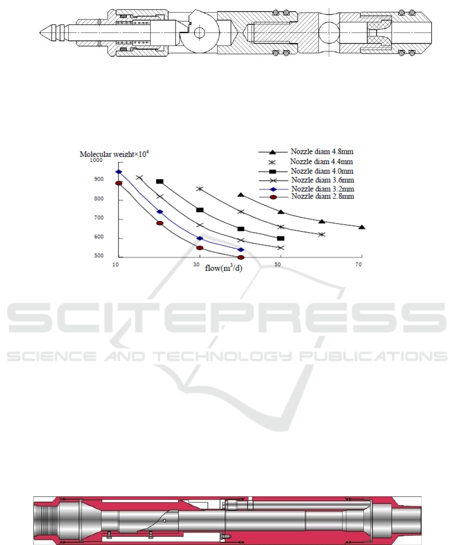
Figure 9. Molecular weight regulating plug.
Performance indicators:
The range of molecular weight adjustment can reach 20-50% In the 50m3/d flow range,show in
Figure 10.
Figure 10. Curve of molecular weight regulator flow--molecular weight.
4. Design of a matching eccentric injection proration device
A medium oriented eccentric polymer injection device is designed innovatively,show in Figure 11
(patent number: ZL201020673891.4). On the basis of the structure of the conventional eccentric
water injection allocator, the guide body is moved up to the center of the eccentric cylinder, that is,
the lower part of the stabilizer. It not only keeps the advantages of high success rate of throwing and
pulling in underside guide structure, but also has the advantages of short throwing and pulling tools
in upside guide structure. The maximum outer diameter of the eccentric injection proration device
working cylinder is 114 mm, The length is 1640mm,The inner diameter is 46mm, The diameter of
eccentric hole is 20 mm, Entering from the bottom of eccentric hole can slow down the blockage of
polymer solution.
The injection proration device is fully compatible with the water injection process, layered water
injection can be realized by directly using water drive Water distribution plug and layered testing and
adjusting technology, and it is compatible with the development of testing and adjusting combination
process in recent years.
Figure 11. Structure schematic of eccentric water injection allocator.
5. Research on integrated separate injection technology with separate mass of the whole
process
Using packers to divide oil layers on different properties, and applying pressure regulators in high
permeable layers. The high molecular weight polymer from wellhead entered the high permeability
Chemical Flooding Process Integration of Low Viscosity Loss Points Injection Technology Research and Application
171
reservoir after reducing injection pressure through pressure regulator. For the low permeability
reservoir, the high molecular weight polymer from wellhead must be degraded by molecular weight
regulator, and the polymer of molecular weight reduction must meet the requirement of injection
scheme. The polymer solution is injected in a way of separate layer and separate mass through dual
control of molecular weight and pressure regulator.
The layer of separate injection is not restricted by grades, and throwing in and pulling and control
can be achieved on any layer. And multi-layer injection can be realized on the class II and class III
reservoirs. The separate injection pipe string is fully compatible with the water flooding injection
process, and it can meet the injection requirement of different displacement stages. There is no need
to replace the pipe string when injection way is changed, and the cost of operation is reduced.
6. Site application
The integrated separate injection technology with separate mass of the whole process for chemical
flooding has been applied for more than 3000 wells on site in Daqing Oilfield, and more than 50
wells in other oil fields by the end of 2017. The statistics indicated that the number of layers
developed in a chemical block was 9.8 percentage higher than that of general wells in Daqing oilfield.
The producing thickness was 10.3 percentage higher. The full well seal rate was 100%. The success
rate of one time throwing in and pulling was 95.6%. The effective flow allocation time of 2-3 layer
was about 1.5-2 days. After application of this technology, The liquid absorption thickness of
polymer injection wells had been obviously increased, and the utilization of poor reservoirs had been
obviously improved.
6.1. test effects
The 1# injection well in a block is divided into 2 reservoirs. There were 3 times to salvage the
plugging device and throw the pressure regulator. There was 1 times of up and down the instrument
for pipe sealing. It took only 0.5 days to complete all above test work. The success rate of throwing
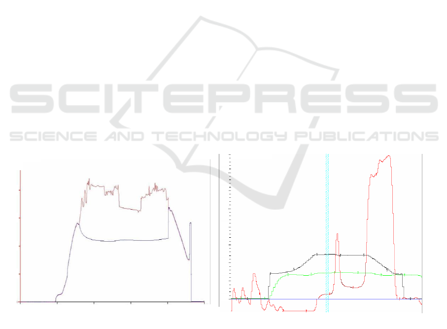
in and pulling was 100%. pipe sealing was qualified,show in Figure 12. It took 1 day to complete
flow test allocation,show in Figure 13.
6.2. separate injection effects
The 2# injection well in a block was generally injected water during the blank water flooding phase.
Only 2 of the 5 layers absorbed water. The used proportion of effective thickness was only 39.2%.
After separate polymer injection, the number of water absorbing reservoirs increased from 2 to 4.
0 .209
0 .418
0 .628
0.146
min( h )
64
6 0 0
1 1 2
56
5 2 5
96
48
4 5 0
80
40
3 7 5
64
32
3 0 0
48
24
2 2 5
32
16
1 5 0
16
8
75
0
Figure 12. 1#well sealing result. Figure 13. 1#wellseparateflow test result.
0
0 .837
P (MPa)
40
20
15
10
5
0
IWMCE 2018 - International Workshop on Materials, Chemistry and Engineering
172
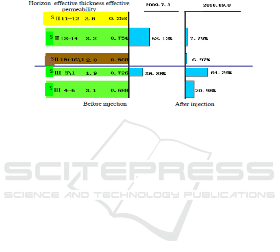
The used proportion of effective thickness increased to 78.5%. The used proportion had Increased by
39.3 percentage,show in Figure 14.
Figure 14. 2#wellContrast diagram of injection profile.
7. Conclusions
A low viscosity loss and high throttle pressure regulating element has been optimized and designed.
The viscosity loss rate decreased from 30% of the water separate injection to less than 10% under the
same conditions.
A wide molecular weight regulating device has been developed. The adjustment range of
molecular weight reached 20-50%. The demand for different molecular weight of different layers in
the same well was satisfied.
Dual control of layered injection volume and layered molecular weight has been realized.
The separate injection pipe string was fully compatible with the water flooding injection process,
and it has met the needs of separate injection in the whole process, including the blank water drive,
chemical flooding and subsequent water flooding. And it will reduce the cost of investment and
production.
References
[1] Li H C H 2012 Present situation of Stratified injection technology in polymer flooding in
Daqing oilfield J. petroleum and natural gas geology 33 (2) 296-301
[2] Gao G L, Yang H, Li H C H and et al 2012 Present situation of Stratified injection technology
in polymer flooding process J. oil production engineering 1 (2) 1-4
[3] Pei X H, Duan H, Cui H Q and et al 2006 Eccentric fragmentation injection technology of
polymer flooding J. Daqing petroleum geology and development 25 (5) 68-69 73
[4] Li J Y 2010 Study and application of polymer flooding with multi layered sub pressure
injection technology J. Inner Mongolia petrochemical industry (1) 130-132
[5] Chen X D, Duan H and et al 2004 Principle and Application of Separate Zone Polymer
Flooding in Multi Zone Reservoirs J. Daqing petroleum geology and development 23 (4)
53-54
[6] Yang Z Q, Wang Y, Liang F M and et al 2001 2-3 ZONAL INJECTION TECHNIQUE OF
POLYMER FLOODING J. Daqing petroleum geology and development (3) 28-29
[7] Cheng J C H, Wang D M, Wu J Z H and et al 2000 Molecular weight optimization for Polymer
flooding J. Acta Petrolei Sinica 21(1) 102-106
Chemical Flooding Process Integration of Low Viscosity Loss Points Injection Technology Research and Application
173
