
Influence Factors to Pipe Pressure on Cast-in Place Pile
Pouring
L Yu
*
, Z L Liu and G Q Zhang
Beijing Xin-Qiao Technology Development Co., LTD, China
Corresponding author and e-mail: L Yu, yuleimabel@163.com
Abstract. Transducer can be used to detect the interface between concrete and slurry by
detecting pressure along pipe. This interface is important to avoid pipe pulled out of concrete
and good for cast-in place p ile construction. But a lot of factors can affect the p ressures on
pipe. In order to detect pressure change around pipe and find out the reasons leading to pipe
pressure changed, some factors such as density, pouring velocity, concrete temperature and
concrete slump must be considered. By means of simu late cast-in place p ile construction in
lib rary, pressure along pipe were detected. Results shows that density and pouring velocity
are the main factors that can be effected on pipe pressure. Concrete temperature and slu mp
are not outstanding factors. From d ifferential pressure curve, interface position between
concrete and air can be found.
1. Introduction
During cast-in place pile construction, pipe is used to pouring concrete into pile hole. The interface of
concrete and slurry is very important. Pressures are different between concrete and slurry.
Transducers can be used to detect this interface by test pressure along pipe. But pressure around pipe
will be affected by different factors. To avoid pressure detecting disturbed and get rid of invalid data,
these factors should be found out. Refer to concrete form, the pressure around pipe may be affected
by pouring velocity, depth, density and temperature. In order to detect pressure change around pipe
and find out the interface of concrete and air, these factors must be considered.
2. Test equipment
Laboratory test was done to simulate pouring. A pipe was used to simulate pile hole. Two
transducers were tied on a steel stick. Put the stick into pipe and pouring concrete into pipe, the
pressure will be detected by transducers on stick. Test equipment is shown in figure 1. Fixed up
method of transducers is shown as figure 2.
The steel stick is divided into 10 parts by steel bars. Every pull stick out 10 centimeters, bars can
be put onto top cover of pipe and keep stick steady. Electronic on multi meter is steadier than handle
it.
Transducer output analog signal, pressure need to be calculated. The distance between
transducers is 30 centimeter.
Yu, L., Liu, Z. and Zhang, G.
Influence Factors to Pipe Pressure on Cast-in Place Pile Pouring.
In Proceedings of the International Workshop on Materials, Chemistry and Engineering (IWMCE 2018), pages 161-166
ISBN: 978-989-758-346-9
Copyright © 2018 by SCITEPRESS – Science and Technology Publications, Lda. All rights reserved
161
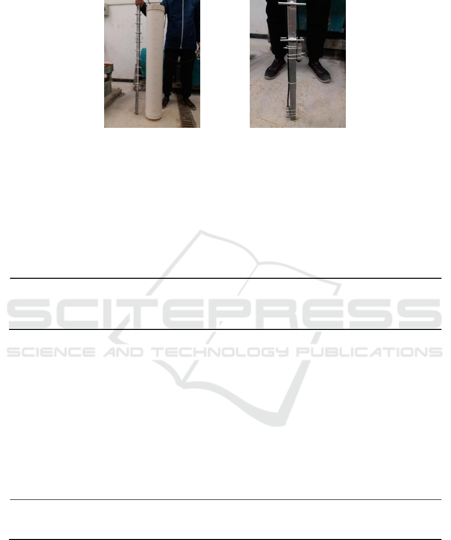
Figure 1. Test equipment for lab test Figure 2. Transducers arrangement
3. Test method
3.1. Test design for density factor
3.1.1. Test design.Three materials was made. They are concrete, mortar and slurry. Keep pouring
velocity, temperature and slumps constant. Just change materials. Detect pressure along pipe. Test
design is shown as table 1.
Table 1.Test parameter for density changing test
Density / kg/m
3
Depth / m
Velocity / L/min
Temperature / °C
Slumps / mm
concrete
1.2
37.68
8
200
mortar
1.2
37.68
8
200
slurry
1.2
37.68
8
200
3.1.2. Test steps. 45L materials were ready for pouring. Fill pipe with a bucket. Keep pouring
continuously. Take 1 minute to tank up the pipe. Keep steady for 5 seconds. Read the electric current
value by multi meter. And then pull out stick 10 centimeters by 10 centimeters. Every 10 centimeters,
read the electric current value until transducer on the bottom of stick is pull out of pipe.
3.2. Test design for pouring velocity factor
3.2.1. Test design. Design two pouring velocities. They are 5L/min and 10L/min. Keep density,
temperature and slumps constant. Just change velocity. Detect pressure along pipe. Test design is
shown as table 2.
Table 2.Test parameter for density changing test
Density / kg/m
3
Depth / m
Velocity / L/min
Temperature /°C
Slumps / mm
2300
1.2
5
8
200
2300
1.2
10
8
200
3.2.2. Test steps. 45L concrete was ready for pouring. Fill pipe with a 5L bucket. Take 1 minute for
pouring 1 bucket. Keep pouring continuously until the pipe was full. We think this pouring velocity
is 5L/min. Read the electric current value when there is display on the multi meter. For velocity of 10
L/min, use 10L bucket to pour the pipe.
IWMCE 2018 - International Workshop on Materials, Chemistry and Engineering
162

3.3. Test design for temperature factor
3.3.1. Test design. Design two temperatures of concrete. They are 8°C and 10°C . Keep density,
pouring velocity and slumps constant. Just change temperature of concrete. Detect pressure along
pipe. Test design is shown as table 3.
Table 3.Test parameter for density changing test
Density / kg/m
3
Depth / m
Velocity / L/min
Temperature /°C
Slumps / mm
2300
1.2
37.68
8
200
2300
1.2
37.68
22
200
3.3.2. Test steps.water with different temperature were used. The water from tap water pipe is 8°C .
For 22°C pouring temperature, mixing hot water and tap water for producing concrete is ok. Take 1
minute to fill pipe full with different temperature concretes respectively. Keep steady for 5 seconds.
Read the electric current value by multi meter. And then pull out stick 10 centimeters by 10
centimeters. Every 10 centimeters, read the electric current value until transducer on the bottom of
stick is pull out of pipe.
3.4. Test design for temperature factor
3.4.1. Test design. Design two level slumps. They are 300mm and 450mm. Keep density, pouring
velocity and temperature constant. Just change slump of concrete. Detect pressure along pipe. Test
design is shown as table 4.
Table 4. Test parameter for density changing test
Density / kg/m
3
Depth / m
Velocity / L/min
Temperature / °C
Slumps / mm
2300
1.2
37.68
8
300
2300
1.2
37.68
22
450
3.4.2. Test steps. 45L concrete was ready. The slump is changed by adding water reducing agent. Fill
pipe with a bucket. Keep pouring continuously. Take 1 minute to tank up the pipe. Keep steady for 5
seconds. Read the electric current value by multi meter. And then pull out stick 10 centimeters by 10
centimeters. Every 10 centimeters, read the electric current value until transducer on the bottom of
stick is pull out of pipe.
4. Results
4.1. Pressure changes by different materials
Figure 3 to figure 6 are about pressure along pipe for different density materials.
Influence Factors to Pipe Pressure on Cast-in Place Pile Pouring
163

Figure 3. Pressure along pipe for concrete Figure 4. Pressure along pipe for mortar
Figure 5. Pressure along pipe for slurry Figure 6. Differential pressure for different materials
The same change rule of pressure on pipe is shown by Concrete, mortar and slurry. Pressure from
transducers decrease by pulling out the stick. At the same mark position, the heavier density is, the
higher pressure is. From differential pressure figure, at point 8, the upper transducer is pull out of
materials into air. At point 12, the bottom transducer is also pull out of materials into air. The
interface of concrete and air is the 8 position.
4.2. Pressure changes by pouring velocity
Figure 7 to figure 8 are about pressure along pipe for different pouring velocity.
At the same depth, the more quick pouring velocity is, the higher press is. This is because more
quick pouring velocity lead to liquid level of concrete higher. The higher of concrete is, the more
pressure is. For the same material, although pouring velocity is different, differential pressure is the
same.
4.3. Pressure changes by temperature
Figure 9 and figure 10 are about pressure along pipe for different temperature.
IWMCE 2018 - International Workshop on Materials, Chemistry and Engineering
164

Figure 7. Pressure for 5L/min pouring velocity Figure 8. Pressure for 10L/min pouring
velocity
Figure 9. Pressure for 8°C temperature Figure 10. Pressure for 22°C temperature
For 8°C and 22°C concrete temperature, at the same depth, for example mark position 3, pressure
are almost the same value. Differential pressure keeps constant no matter in 8°C or 22°C temperature.
Therefore, concrete temperature is not affect to pressure along pipe. From differential pressure curve,
interface of concrete and air can be found and that is point 8.
4.4. Pressure changed by slumps
Figure 11 and figure 12 are about pressure along pipe for different concrete slumps.
Influence Factors to Pipe Pressure on Cast-in Place Pile Pouring
165

Figure 11. Pressure for 300mm concrete slump
Figure 12. Pressure for 450mm concrete
slump
At the same depth, pressure from high slump concrete is less than that from low slump concrete.
But the gap is not outstanding. Slump is not the main reason to lead to pipe pressure rising. From
differential pressure curve, interface of concrete and air can be found and that is point 8.
5. Conclusions
In order to detect pressure change around pipe and find out the reasons leading to wipe pressure
changed, some factors such as density, pouring velocity, concrete temperature and concrete slump
must be considered. By means of simulate cast-in place pile construction in library, pressure along
pipe were detected.
By changing materials, it can be seen that there should be a positive correlation between the
density and the hydrodynamic pressure. By changing pouring velocity, it can be seen that there
should be a positive correlation between pouring velocity and the hydrodynamic press. By changing
concrete temperature, it can be seen that concrete temperature is not effect to pressure along pipe. By
changing concrete slump with water reducing agent, the pressure gap between high slump and low
one is not outstanding. The inducements of pipe pressure changing are not the concrete temperature
and slump, but the density and velocity.
Acknowledgment
This work was supported by the Ministry of Communications and Enterprise Innovation Item [grant
numbers 2015 315 Q13 040].
References
[1] Zhang G Q, Yu L and Liu Z L 2017 Pouring simulation of cast-in place pile construction
Journal of Highway Communication technology 2 150-152
[2] Zhang Z M 2007 Pile foundation project Beijing: China Building Industry Press 10-25
[3] 2008 Technical code for safety of forms in construction JGJ 162-2008 Beijing: China building
industry press
[4] Yu L, Fu Y Y, Zhang J et al 2016 Test ans simulation on pull-out behavior of steelwire in
foam concrete, Journal of Harbin Institute of Technology 48 6 119-123
[5] Yuan S W 2014 Numerical simulation and experimental study of power-law fluid East China
University Of Science and Technology
IWMCE 2018 - International Workshop on Materials, Chemistry and Engineering
166
