
Study on Laminar Flow Field Characteristics in Stirred Tank
with Different Combinations of Dual Impellers
Q X Bu
*
and X Wei
College of Electromechanical Engineering, Qingdao University of Science and
Technology, Qingdao 266061, Shandong, China
Corresponding author and e-mail: Q X Bu, qdbuqiuxiang@163.com
Abstract. The numerical simulation of the flow field generated by dual impellers in glycerol
was carried out by using CFD method and laminar flow model. The flow field structure of
four combinations of impellers under different spacing and constant rotation speed of 200
rpm in the stirred tank is obtained, and axial and radial velocity vectors and velocity
distribution curves are compared and analyzed. The results show that when the distance
between layers is greater than or equal to T / 2, the flow pattern of the flow field is parallel
flow, and the distribution of the two straight blades is the best. When the distance between
layers is less than T / 3, the flow pattern is connected flow,at this time, the combination of the
run-off impeller under the axial propeller is the best.
1. Introduction
With the development of technology and the expansion of production scale, the volume of industrial
agitator reactor tends to be large, and most of the high-diameter ratio is usually greater than 1. The
distribution range of the materials involved is also very wide, which includes the low viscosity fluid
with the fast settlement of solid particles and the non-newtonian fluid with high viscosity and shear
thinning properties. This requires the use of double-layer and multi-layer impellers and effective
combination to ensure the mixing effect of the reactor. At present, the research on the single layer
paddle stirred tank in the flow characteristics
[1-6], mixing time
[7-10], energy dissipation
[11-12],
wake vortex structure
[13-15] and the impact of blade height from the bottom
[16-17] is quite
in-depth and systematic. Lightnin company in USA has developed a new type of axial flow impeller
by using experiment and CFD simulation technology, such as efficient A310, A315 and A340 series
[18-19] that the pitch and width of the blade vary with its radial position, which can effectively
improve the efficiency of mixing, and the D&R work of wing-shaped impeller is gradually being
carrying out in china. The mixing characteristics of two layers and multi-layer impeller [20-29] have
also been studied. Hao Zhigang et al. [30] studied the dispersion of gas in a stirred tank with different
mixing impellers, and considered that the combination of the run-off impeller under the axial
propeller the radial paddle was the most suitable for gas-liquid dispersion. Liang Yingna et al. [31]
used the CFD laminar flow model to simulate the double-layer straight-skewed impeller blade
combination and analyzed the structural characteristics of different forms of flow field.
Up to now, the research on the flow of stirred tanks with two-layer and multi-layer impellers
mainly focuses on turbulent flow conditions. However, the research on the flow field characteristics
of laminar flow in high viscosity system is relatively few, and the effect of layer spacing on flow is
152
Bu, Q. and Wei, X.
Study on Laminar Flow Field Characteristics in Stirred Tank with Different Combinations of Dual Impellers.
In Proceedings of the International Workshop on Materials, Chemistry and Engineering (IWMCE 2018), pages 152-160
ISBN: 978-989-758-346-9
Copyright © 2018 by SCITEPRESS – Science and Technology Publications, Lda. All rights reserved
not considered. For the double-layer impellers reactor, the flow structure is mainly determined by the
geometric combination of the two layers of paddles and the interaction between the two layers of
paddles. Most of the interlayer spacing reported in the literature is relatively large. The vast majority
of interlamellar spacing reported in the literature is relatively large. The flow in a stirred tank can be
thought of as a superposition of two impellers, and the two impellers produce their own flow patterns
with little or no interaction. However, when the distance between layers is small, the interaction
between impeller jets is very obvious and the flow field becomes very complicated. Due to the
unpredictability of such complicated flow field, the design and analysis of multi-layer paddle stirred
tank in industrial production have been affected to a certain extent.
Therefore, in this paper, four different two-layer combination impellers consisting of 6-bladed
radial disc turbines (6DT) and pitch 4-bladed turbines (4PBT) are used to simulate the flow generated
by the propeller in glycerin .Using CFD software FLUENT ,numerical simulation is performed to
analyze the flow field characteristics of the combined impellers with two-runoff paddle, two-inclined
impeller and multi-impeller of runoff impeller and inclined impeller at different layer spacings, and
the suitable layer spacing and suitable combination for laminar flow are given impeller form, provide
a useful reference for the design of industrial multi-layer paddle stirred reactor.
2. Stirred tank structure and meshing
Flat-bottomed cylindrical tank diameter T = 210mm, around the four uniform full baffle, baffle width
w= T / 10, tank level of glycerol H = 1.25T, density
= 1259.9kg / m
3
, viscosity
= 0.799
Pa s
; shaft
diameter d = 16mm, impeller diameter D = T/2, width h = D/5, blade thickness
=
2 mm
. Bottom
paddle center height from the bottom of the tank C
1
= T/3, the distance between the center of the
upper and lower impeller is C
2
, the origin is located in the center of the bottom impeller, impeller
around the z-axis rotation. For six-straight turbine blades, blade length a = D/4, disk diameter d =
3D/4, for diagonal quad-blade, hub diameter d
1
=20mm height. Stirrer b=22mm speed are N=200rpm,
corresponding to the leaf tip linear velocity
1.15m/s
tip
U
, Reynolds number
57.95
e
R
, the flow
within the tank is in the laminar flow state.
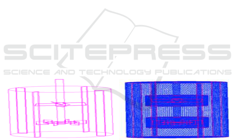
Figure 1. Model configuration and mesh of the stirred tank.
The whole calculation domain is divided into two sub-regions of stator and rotor. The rotor region
adopts the rotating coordinate system, and the static coordinate system is adopted in the static
subregion. Using unstructured tetrahedron grid for discrete, as shown in Figure 1, the rotor area uses
a more detailed grid whose cell number is about 346000, and the number of the stator area cell grid is
about 358000, which is sparse.
Study on Laminar Flow Field Characteristics in Stirred Tank with Different Combinations of Dual Impellers
153
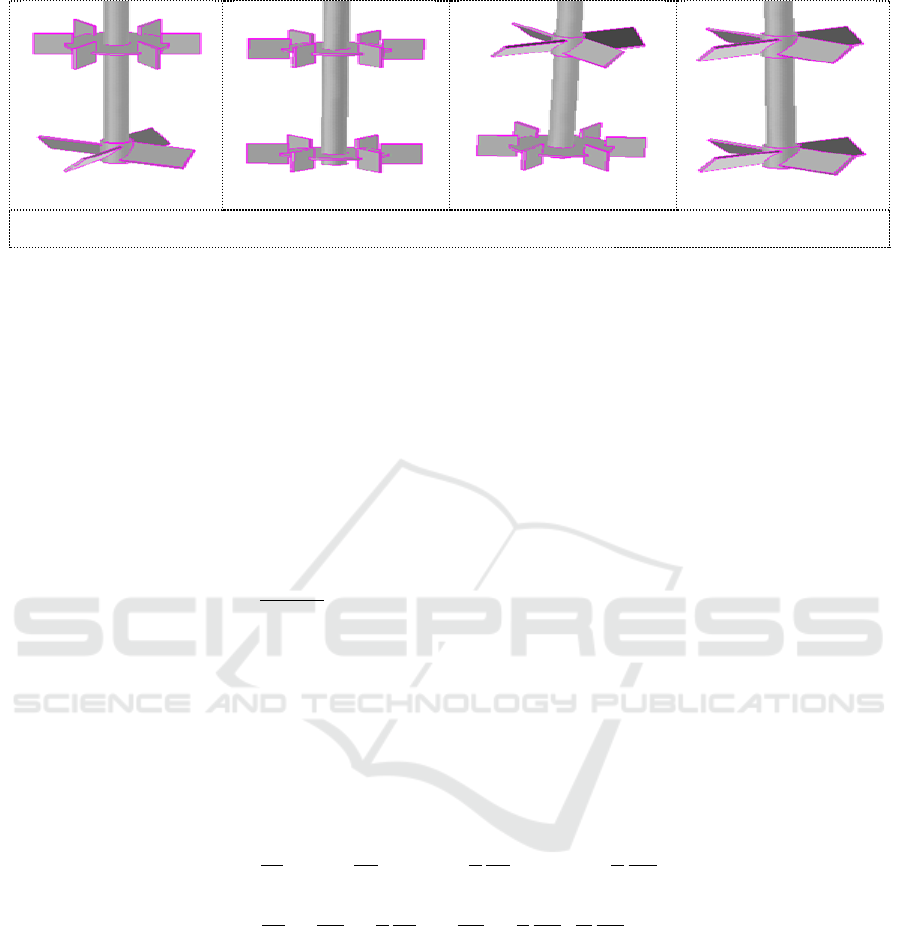
(a) PBT+6DT
(b) 6DT+6DT
(c) 6DT+ PBT
(d) PBT+ PBT
Figure 2. Configuration of the different impeller combinations.
In this paper, the lower impeller is pitch 4-bladed turbine and the upper paddle is 6-bladed radial
disc turbine, which is represented by PBT + 6DT. The other paddle combinations are expressed in
the same way. There are four kinds of impellers in combination: PBT + 6DT, 6DT + 6DT, 6DT +
PBT, PBT + PBT, as shown in Figure 2.
3. Fluid mechanics model and simulation method
Assumptions: (1) The time-averaged movement of the fluid is a steady flow, ignoring the effect of
the periodic motion of the impeller on the macroscopic movement of the fluid. (2) The fluid is a
continuous incompressible fluid.
In the numerical analysis, the fluid control equation can be written as the following conservation
form:
div div grad S
t
u
(1)
Where:
is the fluid density, t is time,
is the generalized diffusion coefficient, S is a
generalized source term,
is a field variable that varies with time,
u
is the velocity vector whose
component is represented by
rz
u u u
, ,
in the cylindrical coordinate system.
The mixing tank used for the simulation is a flat-bottomed cylindrical structure. In order to
facilitate the analysis and the characteristics of the mixing tank, the governing equation can adopt the
following cylindrical coordinates:
11
zr
u r u u
t z r r r
11
rS
z z r r r r r
(2)
The model boundary conditions are set as follows: the symmetry boundary condition are used at
the free surface and the interface between the rotor and the stator is set to interface condition. Using
Multiple Reference Frames (MRF) method, the fluid in the rotor region is set to rotate at the same
speed as the impeller while the fluid in the stator region is stationary. The inner wall of the tank is
defined as a stationary wall condition, and the stirring shaft and the paddle are set as moving wall.
The stirring shaft rotates relative to the stator and the impellers do not rotate with the rotor.
The steady-state implicit separation algorithm was used and the Laminar viscosity model was
chosen. The momentum was discretized by the first-order upwind scheme, and the SIMPLEC
algorithm was used for the coupling of pressure and velocity. The convergence residuals of all the
variables were all less than 1
10
-4
. And the initial conditions is zero.
IWMCE 2018 - International Workshop on Materials, Chemistry and Engineering
154
4. Calculation results and discussion
The velocity field is the basis for optimizing the stirring reactor, and the distribution of shearing rate
can be obtained, also the distribution of displacement can be obtained by differentiating the velocity
field. On the basis of obtaining the velocity field, the distribution of temperature field and
concentration field can be obtained with the proper model equation. Besides, the problems of the
power dimensionless number, the cycle time distribution and the mixing time can be solved.
Therefore, the following is mainly for the analysis of the velocity field distribution, taking the axial
longitudinal section of stirred tank as the object of the study.
Figure 3~ 6 shows distribution curves of the axial velocity and radial velocity of four combined
paddle agitators in different radial positions and y=0, z from -70mm to 193mm. In the paper, when
the axial velocity is the same as the positive direction of z axis, the axial velocity is positive, and vice
versa. The radial velocity is positive when the stirred slurry is pointing to the direction of the cell
wall, and vice versa.
1) Layer spacingC
2
=T/2:
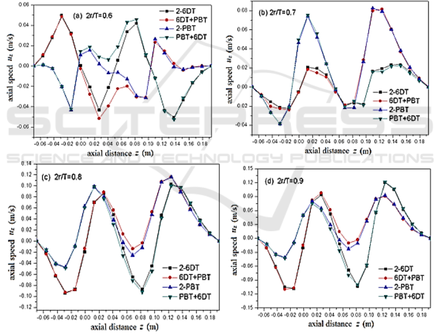
Figure 3. Axial profiles distribution of axial speed at different radial positions.
Figure 3 shows the the variation of axial velocity along the axial profiles at different radial
positions, and at the bottom and top of the trough, the axial velocity is zero. As shown in Figure 3 (a),
at 2 r/T = 0.6 radial position, the axial velocity distribution of the combined impeller agitators with
two-layers six straight blades (2-6DT) is superior to the other impeller, embodying in: under the
lower impeller z = -28 mm, the first upward (positive) velocity perturbation appeared with a value of
Study on Laminar Flow Field Characteristics in Stirred Tank with Different Combinations of Dual Impellers
155
0.05 m/s; After the first wave, axial velocity curve downwards rapidly (positive is becoming
negative). Above the lower impeller z = 27 mm, the first downward (negative) velocity trough
appeared with the value of 0.044 m/s, slightly inferior to the 0.05 m/s trough wave value of
6DT+PBT combined impeller agitators; Then the velocity curve changes the direction again, and at z
= 82 mm (below the upper propeller), the second velocity wave appeared with the value of 0.043 m/s.
Afterwards, the axial velocity changes from the positive to the negative again. At z = 138 mm (above
the upper blade), the second velocity trough is obtained with the value of 0.05 m/s. In the distance
from the second trough to the liquid level, the axial velocity decreases gradually and becomes zero at
the liquid level. From Figure 3 (b), we can see that the positive and negative of the axial velocity of
6DT change, which reveals that between the radial position of the 2 r/T = 0.6 and 2 r/T = 0.7, there
exists a whirlpool. While axial velocity direction of PBT at different radial position has remained the
same, indicating that the whirlpool radius formed by PBT is less than 6DT. From Figure 3 (c) (d) we
can see, with the enlargement of the radial position, a variety of combinations are showing a curve of
two peaks and troughs, and the axial distribution of 2-6DT gets obvious advantages, the maximum
axial velocity reaches 0.11 m/s. The above analysis shows that the axial velocity distribution of the
2-6DT is the best at the layer spacing of 0.5T, which is better for the axial mixing of the fluid than
the other impellers.
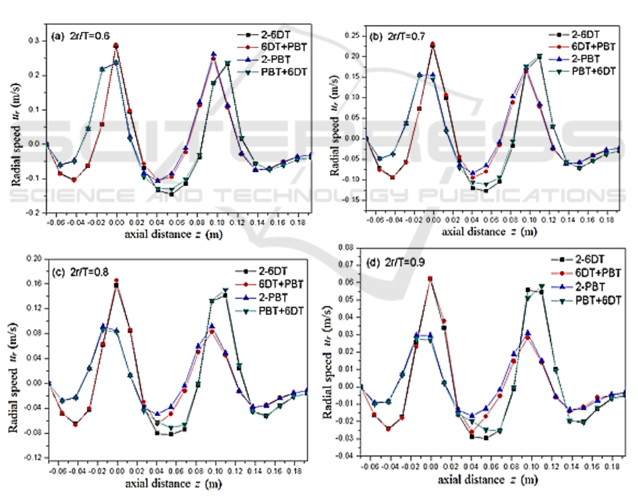
Figure 4. Axial profiles of radial speed at radial positions.
Figure 4 is the variation of radial velocity along the axial height at different radial positions.
Combined with Figure 3, we can see that the flow field is superimposed by two single impellers
IWMCE 2018 - International Workshop on Materials, Chemistry and Engineering
156
under the layer spacing, and there is a parallel flow between the layers, which consistents with the
previous analysis of the flow field structure. Further observation shows that the radial velocity at the
bottom and top of the groove is also zero. The radial velocity changes of different oar types show the
same wave pattern, and the radial velocity distribution of the 2-6DT is the best, as shown in Figure 4
(a) for the 2-6DT.
The radial velocity is negative in the range of z=-20mm from the tank bottom to the lower
impeller, which is one of the vortex ring regions. The maximum magnitude of negative radial
velocity appears at z=-43mm and its value is -0.11m /s. In the range of z=-20 ~ 20mm, the radial
velocity is positive, which is exactly near the upper and lower level of the lower impeller. Because of
the effect of the paddle, the fluid flows to the cell wall and reaches the maximum at z=0, which is
0.29m /s. In the middle of the upper and lower impellers, the negative radial velocity is the maximum
and the maximum value is -0.15m /s due to the joint action of the two vortex rings. The second
maximum value of the positive velocity appears near the upper impeller, and its value is similar to
the first positive maximum magnitude of radial velocity, which is 0.24 m/s. Above the upper impeller,
the third peak of the negative radial velocity, which is the upper vortex ring area. From the vortex
ring area to the liquid level, the radial velocity becomes zero gradually.
From the above analysis we come to the conclusion that the two larger positive radial velocities
occur on the near edge of the upper and lower impeller, and the three smaller negative radial
velocities appear below the lower impeller, between the dual impellers, and above the upper
impeller.The positive velocity is greater than the negative velocity, while the negative velocity
between dual impellers is greater than below the lower impeller and above the upper impeller. This
indicates that the energy loss of the radial flow colliding tank wall is caused by the paddle tip and the
backflow velocity decreases. However, the backflow of double - layer vortex ring is combined to
make its radial velocity greater.
Through the comparative analysis, when the spacing between the layers is greater than or equal to
0.5T, the flow field is the superposition of two single impellers. In the four combined impellers, the
2-6DT combination is the best.
1) Layer spacing C
2
=T/3:
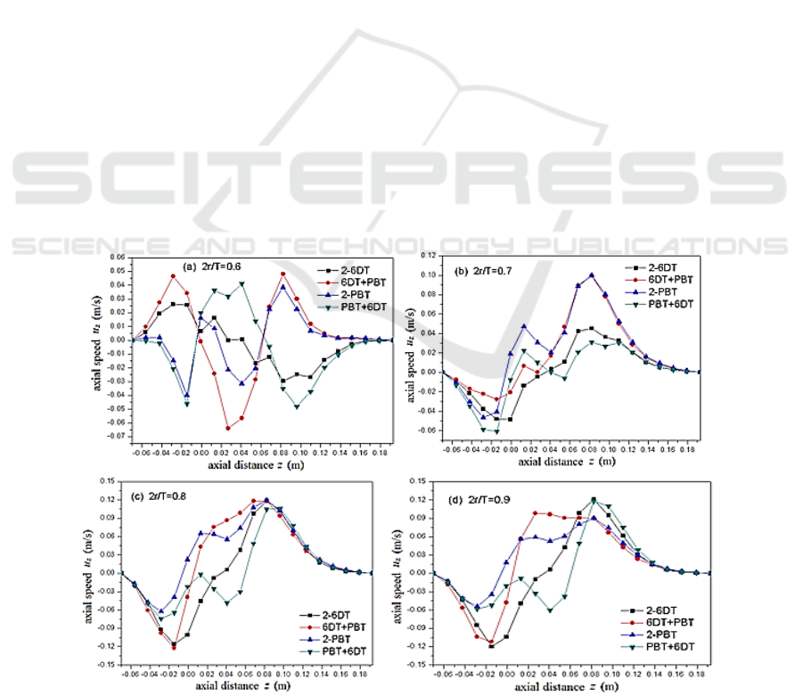
Figure 5. Axial profiles of Axial speed at radial positions.
Study on Laminar Flow Field Characteristics in Stirred Tank with Different Combinations of Dual Impellers
157
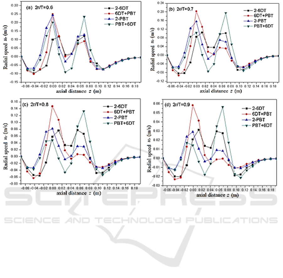
Figure 6. Axial profiles of radial speed at radial positions.
As can be seen from Figure 5 (a), the combination form of 6DT+ PBT is the best when the layer
spacing is C
2
=T/3, namely the bottom is the radial flow impeller, and the upper part is the axial flow
impeller combination. Take the combination of 6DT+ PBT as an example: the axial velocity at the
bottom of the groove is zero, and then the velocity of upward (positive) along the z-axis increases
gradually. At z=-28mm, the first upward axial velocity peak is obtained, which is 0.047m/s. Above
the lower oar, z=27mm, the maximum magnitude of axial velocity of downward (negative) is reached,
which is -0.064 m/s. With the increase of axial height, above the upper impeller z=85mm, the second
upward axial velocity peak is obtained, which is 0.048m/s. Then the axial velocity decreases
gradually, and the axial velocity becomes zero at the liquid level. When in 2 r/T = 0.7 radial position,
as shown in Figure 5(b), axial velocity of 6 DT oar steers, so between the two radial position there
exist vortex. While the Figure 5(b) is closer to the vortex, making 6 DT oar axial velocity decrease;
With the increase of the radius, the axial velocity distribution of 6 DT + PBT combination is
generally better than other one, especially areas between the two oars get obvious advantages, as
shown in Figure 5(c), (d), it is highly advantageous for the axial mixing of fluid.
From Figure 6 we can see that, when layer spacing is T / 3, there is the tendency of "continuous
flow" between two impellers. The lower impeller sucks almost all of the fluid that is discharged by
the upper impeller, forming the whole kettle large cycle. Axial flow between layers is greatly
enhanced, but the radial velocity decreases accordingly, from the point of velocity curve, 6 DT +
PBT is the best combination.
When layer spacing C
2
= T / 4, layers are completely "continuous flow" (due to the page
limitation, this paper does not show its axial and radial velocity distribution), and the axial velocity
gradient between the layers is enhanced obviously, the upper and lower two impellers combining 2 to
1, like a paddle. 6 DT + PBT combination advantage is more obvious, the fluid that is discharged by
IWMCE 2018 - International Workshop on Materials, Chemistry and Engineering
158

the upper PBT was almost sucked by the lower impeller vertically. The simulation results are similar
to the literature
[31], which verifies the correctness of the simulation results in this paper.
Based on the above analysis, when the layer spacing is less than or equal to T / 3, flow features
with the continuum between the layers and layer partition gradually disappears. The axial flow will
no doubt greatly enhance the fluid mixing. According to the velocity distribution curve of different
radial positions, the 6DT+ PBT combination has the advantage.
5. Conclusions
1) When layer spacing is greater than or equal to T / 2, the flow field is for the superposition of
two single impellers, and there exists the partition phenomenon between layers. Its flow is
parallel. The flow field structure of the four combinations is four vortex ring pattern, in
which axial and radial velocity distribution of the 2-6DT combination oar is relatively good.
2) When layer spacing is less than or equal to T /3, the flow in the kettle is the connection flow;
When the spacing of the layers is less than or equal to T /4, the two upper and lower
impellers merge into one, like a single impeller. The flow field structure is two upper and
lower vortex rings model, and the axial flow is significantly enhanced. Therefore, the
combination of 6DT+ PBT is more conducive to fluid mixing under smaller layer spacing.
3) In the four agitators, the flow field structure at the bottom of the lower oar is almost
impervious to the spacing of the layers.
Nomenclature
fluid density (kg/m3)
t
time (s)
generalized diffusion system s generalized source item.
field variable
u
velocity vector (m/s)
u
r
radial velocity component (m/s) u
z
axial velocity component (m/s)
T tank diameter (m) N stirring speed (RPM)
Acknowledgements
The work was supported by the Shandong Provincial Natural Science Foundation of China (Grant No.
ZR2014EEM017) and Project Shandong Provincial Science and Technology Development planning
Program of China (Grant No. 2013YD09007).
References
[1] Wu J, Zhu Y and Pullum L 2001 J. Trans IChemE 79 899
[2] Armenante P M and Chou C C 1996 J. AIChE J 42 42
[3] Hou S D, Wang Y C and Shi L T 1996 J. Journal of Chemical Engineering of Chinese
Universities 10 196
[4] Hou S D, Zhang Z, Wang Y C amd Shi L T 2000 J. Journal of Chemical Industry and
Engineering 51 70
[5] Mavros P 2001 J. Trans IChemE 79 113
[6] Zhou G Z, Wang Y C and Shi L T 2002 J. Journal of Beijing University of Chemical
Technology 29 15
[7] Lunden M, Stenberg O and Andersson B 1995 J. Chem. Eng. Commun. 139 115
[8] Jaworski Z and Dudczak J 1998 J.bComputers Chem. Eng. 22 293
[9] Schmalzriedt S and Reuss M 1998 Application of Computational Fluid Dynamics to
Simulations of Mixing and Biotechnical Conversion Processes in Stirred Tank Bioreactors
(Paris: Proceedings of 9th Europe Conference on Mixing) PP171 -178
[10] Zhou G Z, Wang Y C and Shi L T 2003 J. Journal of Chemical industry and Engineering 54
886
Study on Laminar Flow Field Characteristics in Stirred Tank with Different Combinations of Dual Impellers
159

[11] Khan F R, Rielly C D and Brown D A R 2006 J. Chem. Eng. Sci. 61 2799
[12] Gabriele A, Nienow A W and Simmons M J H 2009 J. Chem. Eng. Sci. 64 126
[13] Schafer M, Yianneskis M, Wachter P and Durst F 1998 J. AIChE J 44 1233
[14] Ranade V V, Perrard M, Le Sauze N and 2001 J. Trans IChemE 79 3
[15] Ranade V V, Perrard M, Xuereb C and Bertrand J 2001 J. Trans IChemE 79 957
[16] Montante G, Lee K, Brucato M and Yianneskis M 2001 J. Chem. Eng. Sci. 56 3751
[17] Ochieng A, Onyango M S, Kumar A and Musonge P 2008 J. Chem. Eng. Process 47 842
[18] Bujalski W, Takenaka K, Paolini S, Jahoda M, Paglianti A, Takahashi K, Nienow A W and
Etchells A W 1999 J. Trans IChemE 77 241
[19] Oscar K and Suzanne M K 2009 J. Chem. Eng. Res. Des. 87 280
[20] Li L C, Wang J J, Gu X P, Feng L F and Li B G 2009 J. Journal of Zhejiang University
(Engineering Science) 43 463
[21] Min J, Gao Z M, Jiang Y and Shi L T 2005 J. The Chinese Journal of Process Engineering 5
495
[22] Ding W Y, Wang Y C, Gao Z M, Shi L T and Liu Q 1999 J. Journal of Chemical Engineering
of Chinese Universities 13 352.
[23] Mao Y, Pan J Z, Niu G R, Min J and Gao Z M 2006 J. Journal of East China University of
Science and Technology(Natural Science Edition) 32 357
[24] Joelle A and Catherine X 2006 J. Chem. Eng. Sci. 61 2913
[25] Harvey III A D, Wood S P and Leng D E 1997 J. Chem. Eng. Sci. 52 1479
[26] Shewale S D and Pand IT A B 2006 J. Chem. Eng. Sci. 61 489
[27] Zhu J, Liu Z H, Zheng X P, Chen C and Wang Y D 2015 J. CIESC Journal 66 896
[28] Yang F L, Zhou S J and Wang G C 2013 J. Journal of Chemical Engineering of Chinese
Universities 27 585
[29] Ding Y, Zong Y, Xi Z H and Zhao L 2015 J. Journal oI East China University of Science and
Technology (Natural Science Edition) 41 750
[30] Hao Z G, Bao Y Y and Gao Z M 2004 J. Journal of Chemical Engineering of Chinese
Universities 18 547
[31] Liang Y N and Gao D R 2008 J. Chinese Journal of Mechanical Engineering 44 290
IWMCE 2018 - International Workshop on Materials, Chemistry and Engineering
160
