
The Design and Analysis of Free Bending Tube Bending
Machine
Y S Li, Z M Yue
*
, F R Liu, J S Qi and J Gao
School of Mechanical, Electrical and Information Engineering, Shandong University
at Weihai, China
Corresponding author and e-mail: Z M Yue, yuezhenming@sdu.edu.cn
Abstract. The existing devices for the 3D tube bending normally are complex on the
mechanism and unmanageable. In this study, a new kind of tube bending machine which can
realize the free bending in space through using the principle of superimposing two main parts,
which provide more degree of freedom for the new developed machine. Screw system is
established based on screw theory, then the analysis about the degree of freedom of each
main part and the overall mechanism has been conducted.
1. Introduction
In addition to good processing and forming properties, the tube material has the characteristics of
high strength stiffness and high material utilization. The demand for high quality and high-precision
tube bender is increasing, and owing to excellent characters like high strength and stiffness and high
efficient utilization, the bent tube have an important application in many fields of national production,
such as the furniture, fluid arrangements, aviation, aerospace, automobile and precision machinery
[1,2]. The bending process of the metal tube is one common forming process. The purpose of this
process is translating the tube into the defined profile with specific bending curvature, angle and
shape. Traditional bending methods of tubes include rotary-draw bending, press bending and roll
bending [3].
Tube bender is the main mechanical equipment for tube bending process. At present, there are
mainly CNC bending machine, press machine, roll bending machine, draw bender and so on.
However, with the demand for complex spatial tube is increasing, there are lots of limitations in
traditional tube benders which can only be fit for the profiles which have simple shapes and bend
radii without continuous changing. The latest technology of 3D free forming can overcome the
shortcomings above, and it can make tube shaped precisely in 3D space.
As the complex spatial tube has been successfully applied in material forming field , lots of design
about the 3D bender for tube has been arising in recent years. This kind of technology makes use of
the principle of the modeless forming and the hydraulic servo control technology, it uses servers to
design radian of tube, and finally realize the control of final forming shape of tube. This kind of
technology has changed traditional process of die forming of tube, and overcome the disadvantages
and limitations of die forming which can make forming process flexible and convenient. It can also
improve greatly the efficiency and precision of the production process.
Li, Y., Yue, Z., Liu, F., Qi, J. and Gao, J.
The Design and Analysis of Free Bending Tube Bending Machine.
In Proceedings of the International Workshop on Materials, Chemistry and Engineering (IWMCE 2018), pages 115-121
ISBN: 978-989-758-346-9
Copyright © 2018 by SCITEPRESS – Science and Technology Publications, Lda. All rights reserved
115
2. Principle of 3D free bending
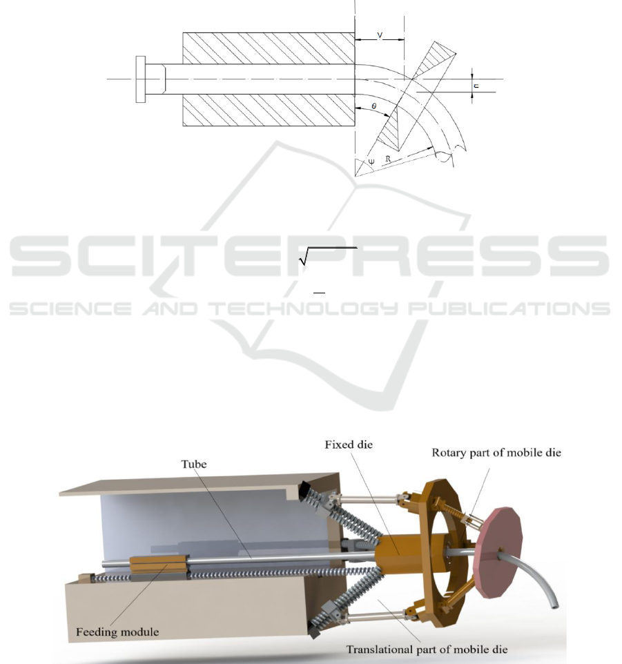
The basic principle of bending is shown in Figure 1. The tube which is driven by a propulsion
equipment through fixed die and mobile die. The mobile die can move and rotate in space. The move
of mobile die can adjust distance V between the exit of the fixed die and the center of the mobile die
and offset u between the center line of the fixed die and the center of the mobile die [4]. The rotation
of the mobile die is to control the deflection angle of the mobile die
. The movement and deflection
of the rotary platform will exert a force on the tube. The translation and rotation of the mobile die
will exert a pushing force, tube will be bent under the influence of this force as shown in Figure 1.
The bending radius of the tube R is determined by distance V, offset u and deflection angle
[5, 6].
The relationship between each parameter is as Eq. (1).
Figure 1. Principle of 3D free bending.
22
arcsin
u R R V
V
R
(1)
3. Design and analysis of new 3D bender
The new 3D bender referred in this article is shown in Figure 2. This device mainly includes four
parts, they are feed mechanism, fixed die, translational part of mobile die and rotary part of mobile.
The feed mechanism can clamp tube and push tube forward. The translational part of mobile die is a
3PUU structure, it can make the mobile platform move along any direction in space. The rotary part
of mobile die which can make platform rotate is a 2RPS-RS structure.
Figure 2. Global design of tube bending machine.
IWMCE 2018 - International Workshop on Materials, Chemistry and Engineering
116
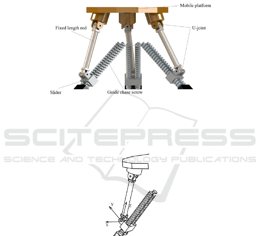
3.1. The analysis on degree of freedom of translational part
The 3PUU structure which is researched in this article has three parallel branched chains which are
axial symmetrical distributed in space. On each branched chain, the two ends of the fixed length rod
are connected to the moving platform and slider with the universal joint (U-joint), and slider can
move on guide chase screw. These joints are connected in P-U-U order. Its structure chart is shown
in Figure 3.
Figure 3. The translational part of mobile die.
Coordinate system is established as shown in Figure 4. X -axis and Y –axis are along the two axes
of U-joint; Z - axis is perpendicular to crosshead plane of U-joint, it can be also said as Z - axis along
the direction of fixed length rod. Under the initial assembly position, the screw system of each branch
chain is as Eq. (2).
Figure 4. Coordinate system of branch chain.
The Design and Analysis of Free Bending Tube Bending Machine
117

1
11
2
3
4
4
55
0 0 0; 0
1 0 0; 0 0 0
0 1 0; 0 0 0
0 1 0; 0 0
1 0 0; 0 0
$
ef
$
$
$
d
$e
(2)
To calculate reciprocal screw of five kinematic screw, all the variables in Eq. (2) are import into
formulation
0
r
i
$$
(
1,2,3,4,5i
), and the constraint screw of single branched chain is obtained
as Eq. (3).
0 0 0; 0 0 1
r
$
(3)
In Eq. (3), the first three elements of the constraint screw are all 0, so this screw is constrained
couples. This couples limits the rotation around the Z-axis. Because of the symmetry of this structure,
the screw system of the other two branched chains is the same as the first one, and their direction
correspond to direction of respective fixed length rod. Because three couple of three symmetrical
branched chain are not paralleled to each other and linearly independent, three independent
constraints act on the mobile platform. These three constrained couples constrain three rotational
freedom, so mobile platform has only three translational freedom. Therefore, mobile platform can
move along X-axis, Y-axis, Z-axis and the direction of any linear combination of them.
Besides, the degree of freedom of this mechanism can also be calculated by the G-K formulation.
It is obvious that there are no common constraint and redundant constraints in this device. So the
degree of freedom of this mechanism can be calculated by Eq. (4).
1
1 6 8 9 1 15 0 3
g
i
i
M d n g f v
(4)
Order of mechanism
n The number of moving part in the mechanism
g The number of kinematic pair
fi The number of degree of freedom of kinematic pair
v The number of redundant constra s
d
int
The results of calculations is consistent with the theoretical analysis and confirm the correctness of
the analysis.
3.2. The analysis on degree of freedom of rotary part
The 2RPS-RS structure which is researched in this article is shown in Figure 5. This device has three
branched chains, two of them are the same. The lower end of the guide chase screw is connected to
the moving platform with revolute (R-joint) and the upper end of the screw is connected to the rotary
platform with sphere joint (S-joint) on these two branched chains. The third branched chain is that
the lower end of fixed length rod is connected to mobile platform with revolute (R-joint) and the
upper end of the rod is connected to the rotary platform with sphere joint (S-joint).
IWMCE 2018 - International Workshop on Materials, Chemistry and Engineering
118
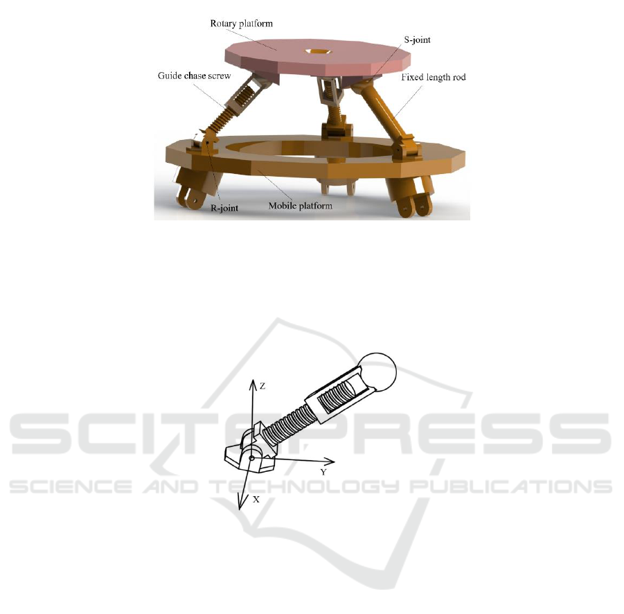
Figure 5. The rotary part of mobile die.
For the first branched chain, the coordinate system is established as shown in Figure 6. The origin
is on the first kinematic pair, and X-axis is along the axis of this R-joint, and Z-axis is perpendicular
to basic plane. So the screw system of this branch chain is as Eq. (5).
Figure 6. Coordinate system of first branch chain.
1
2
3
4
5
1 0 0; 0 0 0
0 0 0; 0 e
1 0 0; 0
0 1 0; 0 0
0 0 1; 0 0
$
$f
$ f e
$f
$e
(5)
By the same method, the constraint screw of this branched chain can be received as Eq. (6)
1 0 0; 0
r
$ f e
(6)
For the third branched chain, the coordinate system is established by the same way as shown in
Figure 7. So the screw system of this branch chain is as Eq. (7).
The Design and Analysis of Free Bending Tube Bending Machine
119

Figure 7. Coordinate system of third branch chain.
1
2
3
4
1 0 0; 0 0 0
1 0 0; 0
0 1 0; 0 0
0 0 1; 0 0
$
$ f e
$f
$e
(7)
By calculating, two linearly independent constraint screws are obtained as Eq. (8).
=;
=;
r
1
r
2
$ 1 0 0 0 f e
$ 0 f e 0 0 0
(8)
For the rotary part, the first two chains have similarly constraining force. This force act on the
rotary platform, and it is through the center of respective branched chain’s sphere joint and parallel to
the axis of revolute joint. The third branched chain has two constraining force, one of them is same as
force of the first two chains, the other one along the direction of fixed length rod. These four
constraining force are linearly independent and they restrain four rotary platform’s degree of freedom.
It is find that the three translations and a rotation around Z-axis of rotary platform are limited by
analyzing. So rotary platform can only have two-dimensional rotation in the plane.
It is obvious that there are no common constraint and redundant constraints in this device. So the
degree of freedom can also be calculated according to the G-K formulation as Eq. (9).
1
1 6 7 8 1 14 0 2
g
i
i
M d n g f v
(9)
The results of calculations is consistent with the theoretical analysis and confirm the correctness of
the analysis.
4. Conclusions
A new kind of tube bending machine is proposed in this article for the demand of complex spatial
tube is increasing significantly. The mobile die of this machine contains two parts, the one is a 3PUU
translational part, the other one is a 2RPS-RS rotary part. By the analysis based on screw theory, it is
find that this 3PUU part has three translational degree of freedom, which means it can move along
any direction in space. The 2RPS-RS rotary part has two rotational degree of freedom. After
combining these two parts, the mobile die has five degree of freedom, the condition of free bending
of tube will be satisfied. More complex spatial tube can be designed and manufactured by this new
developed machine.
IWMCE 2018 - International Workshop on Materials, Chemistry and Engineering
120

Acknowledgement
The authors would like to acknowledge the financial support from National Natural Science
Foundation of China (NO.51605257).
References
[1] Wu J J, Zhang Z K, Shang Q, Li F Y, Wang Y A, Hui Y and Fan H 2017 A method for
investigating the springback behavior of 3D tubes J. INT J MECH SCI
[2] Song F F, Yang H, Li H, Zhang M and Li G J 2013 Springback prediction of thick-walled
high-strength titanium tube bending J. CHINESE J AERONAUT 26(05) P1336
[3] D X E, Liu Y F and Feng H B 2010 Deformation Analysis for the Rotary Draw Bending
Process of Circular Tubes: Stress Distribution and Wall Thinning J. STEEL RES INT.
81(12)
[4] Hiroyuki G, Yutaka T, and Ken I 2012 Three-Dimensional Tube Forming Processes with a
New Hydraulic Bending Machine Using Parallel Kinematics J. Int. J. of Automation
Technology
[5] Tang N C 2000 Plastic-deformation analysis in tube bending J. INT J PRES VES PIP. 77(12)
[6] Ma Y N, Xiong H, Wang H, Luo X Y, Jin K, Xu Y, Tao J and Guo X Z 2017 Simulation and
Experimental Study on Three Dimensional Free Bending of Complex Space Elbow J. J
NETSHAPE FORMING E. 9(02)
The Design and Analysis of Free Bending Tube Bending Machine
121
