
A Method of Localization with Multi-Channels UWB Bio-Radar in
Application of Through-Wall Detection
Ziqi Zhang, Fugui Qi, Yang Zhang, Hao Lv, Zhao Li, Miao Liu and Jianqi Wang
*
Department of Electronics, School of Biomedical Engineering, the Fourth Military Medical University, Xi’an 710032,
China.
Email: wangjq@fmmu.edu.cn
Keywords: Bbio-radar, multi-channels, localization, through-wall
Abstract: Recently, technology of ultra-wide band (UWB) bio-radar develops rapidly which becomes a very helpful
method of rescuing for post-disaster like earthquake and also useful surveillance medium for security fields
like anti-terrorists. There are two main aspects of UWB technology that researchers concern namely
technology of targets recognition and technology of targets localization. Most methods about targets
localization based on intersecting of multi arcs cannot determine the location of the targets effectively
because those arcs could not always intersect into one point. In this paper, we proposed a novel method
based on hyperbolic model using multi-channels bio-radar for two dimensional localization. Free-space and
through-wall experiments results indicated that the proposed method could determine the location of targets
accurately and effectively with an average error around 10cm between detection results and real positions.
1 INTRODUCTION
Ultra-wide Band (UWB) bio-radar is a novel kind of
radar combining radar technology and biomedical
engineering technology, and regards organism like
human bodies as the main detection targets, which is
one of the most effective technical methods to
search survivors that applied in some post-disaster
search and rescue operations like the earthquake, the
mine disaster, the debris flow and so on (Qi et al.,
2016; Lv et al., 2016; Liang et al., 2016). Bio-radar
could determine whether there is a life target and its
location within the detection area quickly, which
could provide guidance for professional rescue to
improve accuracy and efficiency of the rescue. The
detection results of bio-radar always contains two
aspects: targets recognition (whether there is a life
target and classification of target types), and targets
location. Actually, targets location technology is
eagerly needed in rescue operations, while it is still a
difficult problem to be solved at the moment
(Nguyen and Pyun, 2015; Monica and Ferrari, 2015).
If the actual position of the trapped target can be
accurately estimated, the limited search and rescue
resources will be better concentrated and the
efficiency of rescue will be greatly improved.
Currently, algorithm of multi arcs intersecting is
commonly used in two-dimensional positioning,
which can easily lead to a circumstance that
different arcs intersect into different points resulting
in failing to locate the life targets. Therefore, this
paper proposed a location method based on
hyperbolic model with multi-channels portable bio-
radar platform, and the experimental results of single
target location indicated that this method could
determine the two-dimensional coordinates of the
target more accurately. The location of multi-targets
is the most challengeable topic in location
technology for the absence of shadowing effect
(Kocur et al., 2011), research in this paper also lays
the foundation for solving the difficult problem of
multi-targets location.
This paper is organized as follow. In Section 2,
the multi-channels UWB bio-radar and antennas
array setup are introduced. Section 3 introduces the
new kind of two dimensional detection method for
life targets based on hyperbolic model and analyses
feasibility of it theoretically. The experimental
results are discussed in Section 4. The conclusion is
given in Section 5 finally.
Zhang, Z., Qi, F., Zhang, Y., Lv, H., Li, Z., Liu, M. and Wang, J.
A Method of Localization with Multi-Channels UWB Bio-Radar in Application of Through-Wall Detection.
In Proceedings of the International Workshop on Environment and Geoscience (IWEG 2018), pages 501-506
ISBN: 978-989-758-342-1
Copyright © 2018 by SCITEPRESS – Science and Technology Publications, Lda. All rights reserved
501
2 MULTI-CHANNELS UWB BIO-
RADAR SYSTEM AND
EXPERIMENTAL SETUP
2.1 Multi-Channels UWB Bio-Radar
System
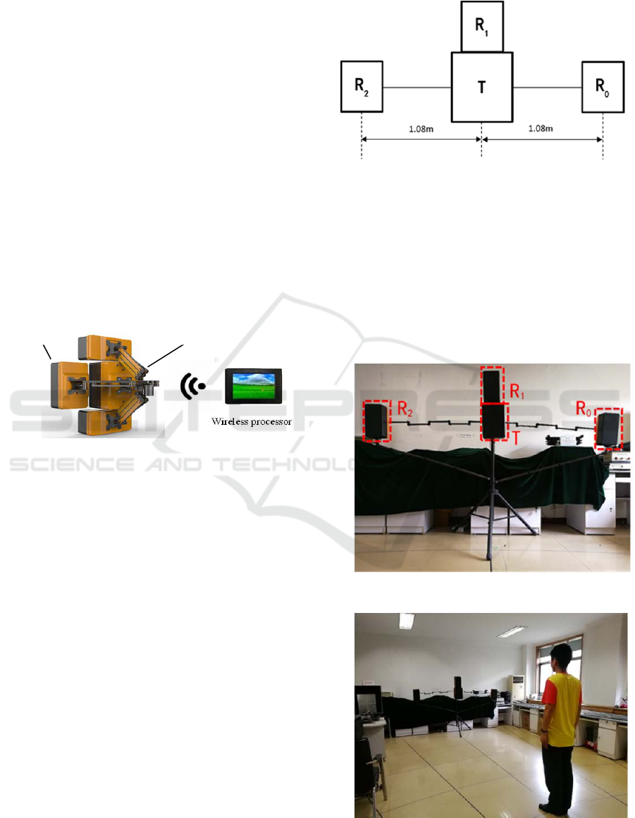
As Figure 1 shows, The multi-channels portable
UWB bio-radar system we adopt consists of UWB
bio-radar antennas with 1 transmitting antenna and 4
receiving antennas, a portable multi degree of
freedom foldable support and a touch-sensitive
wireless processor. Its operating central frequency of
the UWB radar is 400MHz with a band width of
400MHz. The pulse repetition rate is 128 KHz, and
the AD sampling frequency for each channel is 64
Hz, which is sufficient to capture the instantaneous
change of human motion.
Figure 1: Multi-channels UWB bio-radar system.
2.2 Antennas Array and Experiment
Setup
According to previous research (Zhang et al., 2006),
it needs at least 3 channels to avoid “ghost” if the
two dimensional location for a target should be
determined. As Figure 2 shows, an antenna
combination of one transmitting antenna and three
receiving antennas (receiving antennas are marked
as R
0
, R
1
, R
2
and T for transmitting antenna) is
adopted in this paper. The transmitting antenna is
placed in the middle of the array together with the
receiving antenna R
1
on the top of it, another two
receiving antennas are on the two sides of antenna T
with a distance of 1.08m (the folding arms of the R
0
and R
2
are extended to the longest) repectively to
ensure the angle resolution when targets locate at a
relatively long distance. Therefore, they show a
linear array as Figure 2. Thereinto, the box T
contains not only transmitting antenna but host
which controls wifi module connects with wireless
peocessor and coordinate the linear antenna array
smoothly.
Figure 2: A schematic diagram of a linear antenna array.
In this paper, we intend to verify the
effectiveness of the new location method via two
different experimental scenarios, namely free-space
and through-wall. Firstly we conduct the free-space
experiment to verify the principle and then carry out
the through-wall detection experiment, so as to
gradually verify the rationality and correctness of
the novel location method. The two experimental
scenes are illustrated by Figure 3 to Figure 6.
Figure 3: Antenna deployment in free-space scenario.
Figure 4: Experimental scene in free-space scenario.
Wireless processor
Antennas
Foldable suppor
t
IWEG 2018 - International Workshop on Environment and Geoscience
502
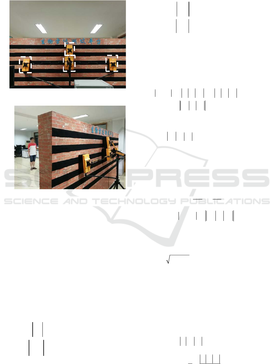
Figure 5: Antenna deployment in through-wall scenario.
Figure 6: Experimental scene in through-wall scenario.
3 TWO DIMENSIONAL
LOCALIZATION METHOD
WITH MULTI-CHANNELS BIO-
RADAR
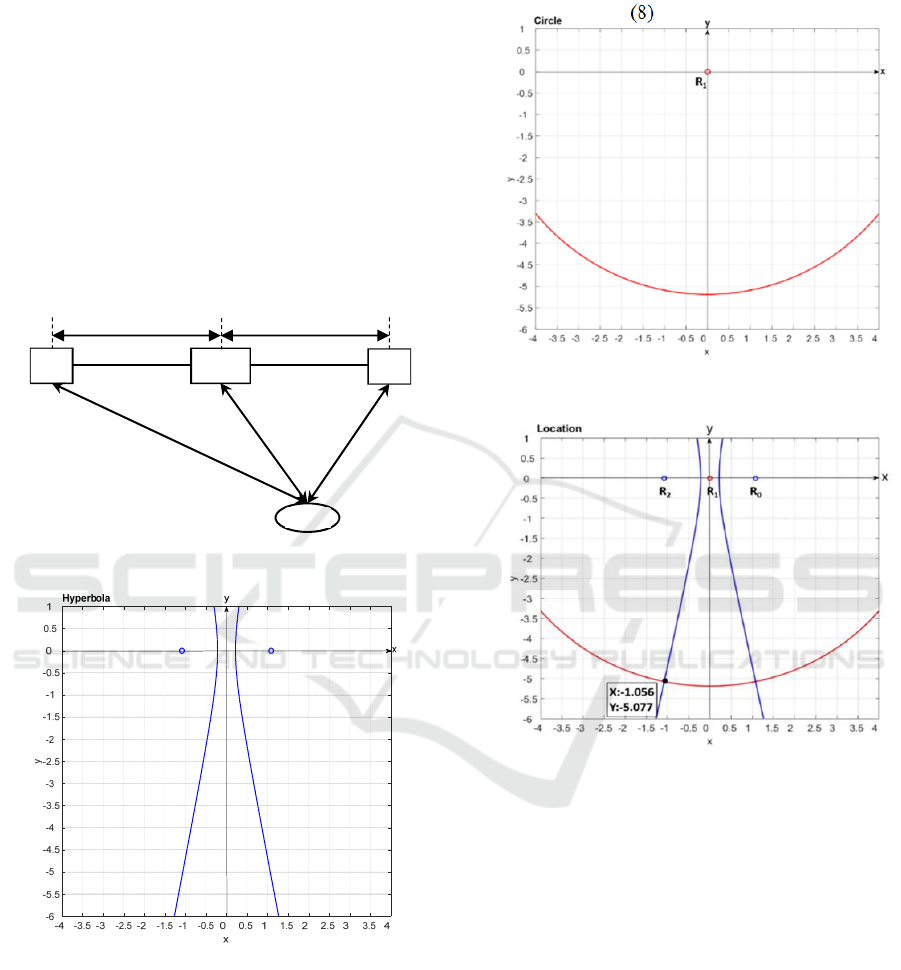
The principle of the localization method is shown in
Figure 7, the antennas array seems like a line from
high angle, the receiver R
1
and transmitter T are
approximately treated as the same point. In Figure 7,
the traveling time of microwave from T to target P is
denoted as τ
p
, while τ
0
,τ
1
and τ
2
denote the traveling
time of reflected microwave from target P to R
0
, R
1
,
and R
2
respectively.
Then, some distances are calculated by
c
p
TP
(1)
00
c
PR
(2)
11
c
PR
(3)
22
c
PR
(4)
where c is the speed of light.
The distance of microwaves that sent from the
transmitter then reflected by the target P to receiving
antennas R
0
, R
1
, and R
2
are L
0
, L
1
, and L
2
respectively, then we can get
02 0 2
02
L L TP PR TP PR
PR PR
(5)
Therefore, the absolute value of difference
between
0
PR
与
2
PR
is equal to that between L
0
and
L
2
which could be acquired by bio-radar easily.
According to the knowledge of analytic geometry, if
the absolute value of the distance difference between
the point P and another two points on the plane is
fixed, then the point P is located on one branch of
the hyperbola with the focus of R
0
and R
2
.
Mathematically,
h2 0
cRTTR
(6)
02 0 2
2
aLL PR PR
(7)
Among them, c
h
is a half focal length of
hyperbola, a indicates the real half axis of hyperbola,
so the imaginary half axis of hyperbola is calculated
by
22
h
bca
. Taking a set of data in the
experiment (whose actual coordinates are (-1,-5)) for
an example, then the hyperbola determined by R
0
,
R
2
and T is acquired as Figure 8 shows. If L
0
>L
2
, the
target is in the left branch of the hyperbola in the
third quadrant of Cartesian coordinates; If L
0
<L
2
, the
target is in the right branch of the hyperbola in the
fourth quadrant of Cartesian coordinates. While, it is
not adequately to calculate on which specific point
of that branch the target locates. Besides, we treat T
and R
1
as the same point, so we can suppose that
τ
p
=τ
1
, namely
1
TP PR
. Then target P is also on the
circle with the radium of r as shown in Figure 9.
1
1
22
TP PR
L
r
(8)
R
2
R
0
T
R
1
A Method of Localization with Multi-Channels UWB Bio-Radar in Application of Through-Wall Detection
503
(8)
If we plot that hyperbola and arc described above
in the same Cartesian coordinate system, they will
intersect at two points as shown in Figure 10. For
this sample of data, due to the L
0
>L
2
, we get (-1.056,
-5.077) by tracking the intersection of the two
curves in the third quadrant. Thus, we accomplished
the two-dimensional positioning of the target P. In
addition, the positioning result have little error
compared with actual position of target namely (-1, -
5). The absolute error is less than 8cm in this
example.
Figure 7: The principle of the localization method.
Figure 8: Hyperbola determined by R
0
, R
2
and T.
Figure 9: Circle determined by R
1
and T.
Figure 10: The method of the ensure the specific
coordinates of the target.
4 EXPERIMENT RESULTS AND
DISCUSSION
In order to describe the position of the target more
easily, we have set up a Cartesian coordinate system
on the ground of the laboratory as Figure 11 and
Figure 12 show. The target positions were divided
into 25 different points and marked with
corresponding number. The position of the host of
bio-radar is set as the origin of coordinates, both
receiving antennas R
0
and R
2
are lied in horizontal
axis. In free-space experiment, most coordinates of
position are integer value except for positions on
right sides of the coordinate system because of the
limitation of the experimental site. In through-wall
T(R
1
) R
0
R
2
1.08m
1 08m
P
IWEG 2018 - International Workshop on Environment and Geoscience
504
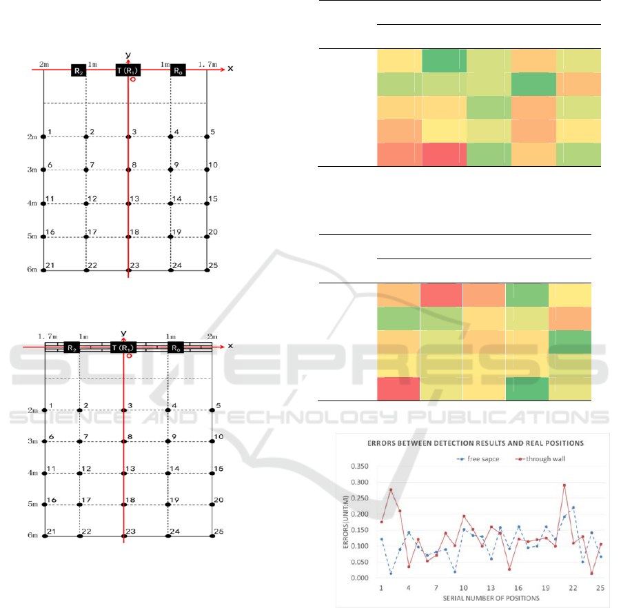
experiment, we let the bio-radar system turn around
and carried out the experiment in opposite direction,
so positions on left sides of the coordinate system is
not integer value as shown in figures below.
Figure 11: Target position division of free-space
experiment.
Figure 12: Target position division of through-wall
experiment.
We calculate the errors between detection results
and real positions. As for the example referred
above, the detection results is (-1.056,-5.077) and
the real coordinates of the positions is (-1,-5), so the
distance between (-1.056,-5.077) and (-1,-5) namely
error is 0.095m. To cooperate with the Cartesian
coordinate system set above, experimental results
are listed in Table1 and Table 2 in the form of
matrix below. Among them, color red indicates a
lager error but color green means a smaller error.
What’s more, we drew data of both the two
scenarios into one line diagram as Figure 13 shows.
Table 1: Errors between detection results and real
positions of free-space
a
.
Ordinate
Abscissa
-2 -1 0 1 1.7
-2 0.122 0.014 0.090 0.143 0.098
-3 0.071 0.082 0.090 0.020 0.152
-4
0.134 0.130 0.060 0.158 0.092
-5
0.161 0.095 0.100 0.161 0.122
-6
0.192 0.221 0.050 0.142 0.067
a
Unit of data in the table: m
Table 2: Errors between detection results and real
positions of through-wall
a
.
Ordinate
Abscissa
-1.7 -1 0 1 2
-2
0.175 0.277 0.210 0.036 0.121
-3
0.054 0.071 0.140 0.102 0.194
-4
0.153 0.100 0.160 0.140 0.028
-5
0.122 0.114 0.120 0.126 0.100
-6
0.291 0.110 0.130 0.014 0.106
a
Unit of data in the table: m
Figure 13: Errors between detection results and real
positions of two scenarios.
5 CONCLUSIONS
This paper proposed a novel two-dimensional
localization method for life target detection using
multi-channels bio-radar based on hyperbolic model.
Actual experimental results show that the proposed
method could avoid the circumstance that different
A Method of Localization with Multi-Channels UWB Bio-Radar in Application of Through-Wall Detection
505

arcs fail to intersect into one point. Moreover, it
could accurately determine the coordinates of a life
target no matter in application of free-space or
trough-wall scenarios.
ACKNOWLEDGMENTS
Research in this paper was supported by National
Natural Science Foundation of China (Grant No.
61327805), Shaanxi Technology Committee (Grant
No. 2016KJXX-03) and National Natural Science
Foundation of China (Grant No. 31600796).
REFERENCES
Kocur D, J Rovňáková and D Urdzík 2011 Mutual
shadowing effect of people tracked by the short-range
UWB radar International Conference on
Telecommunications and Signal Processing
Liang F, et al. 2016 Detection of Multiple Stationary
Humans Using UWB MIMO Radar Sensors 16(11)
1922
Lv H, et al. 2016 Improved Detection of Human
Respiration Using Data Fusion Based on a Multistatic
UWB Radar Remote Sensing 8(9) 773
Monica S and G Ferrari 2015 UWB-based localization in
large indoor scenarios: optimized placement of anchor
nodes IEEE Transactions on Aerospace & Electronic
Systems 51(2) 987-999
Nguyen V H and J Y Pyun 2015 Location Detection and
Tracking of Moving Targets by a 2D IR-UWB Radar
System Sensors 15(3) 6740-6762
Qi F, et al. 2016 Detection and Classification of Finer-
Grained Human Activities Based on Stepped-
Frequency Continuous-Wave Through-Wall Radar
Sensors 16(6) 885
Zhang Y, et al. 2006 Secure localization and
authentication in ultra-wideband sensor networks
IEEE Journal on Selected Areas in Communications
24(4) 829-835
IWEG 2018 - International Workshop on Environment and Geoscience
506
