
Effect of Thrust Structural Pattern on Carbonate Reservoir and Gas
Reservoir Type in the East of Amu Darya Right Bank
Liangjie Zhang
1,*
, Hongjun Wang
1
, Xingyang Zhang
1
, Wenxin Ma
2
, Laiyong Cao
3
and Hongwei
Zhang
1
1
Petrochina Research Institute of Petroleum Exploration & Development, No. 20, Xueyuan Road, Haidian District, Beijing,
China;
2
CNPC Chuanqing Drilling Engineering Company Limited Geological Exploration & Development Research Institute, No.
3, Section 1, Fuqing Road, Chenghua District, Chengdu, Sichuan Province, China;
3
CNPC(Turkmenistan) Amu Darya River Gas Company, No. 9, Advance Road, Changping District, Beijing, China.
Email: zlj520@petrochina.com.cn
Keywords: The Amu Darya Right Bank, structural style, carbonate reservoir, fracture, natural gas
Abstract: The Amu Darya Right Bank is located in the northern part of Turkmenistan. Middle-Lower Jurassic coal-
bearing deposits, Middle-Upper Jurassic carbonate rocks and Upper Jurassic salt rocks are the major
sedimentary assemblages. The east of the right bank is located in the Southwestern Gissar thrust belt, and
the reservoir is the most important risk factor. Based on the fault-related folds theory, have analyzed the
structural pattern of the thrust - fold belt, figured out their effects on development of fractures and carbonate
reservoirs, and influence on natural gas accumulation. The study shows that breakthrough fault-propagation
folds and fault-bend folds dominate the east. With structural highs far away from the primary fault,
breakthrough fault-propagation folds have abundant fractures, but weak dissolution, where the reservoirs
and gas pools are mostly fracture-pore type, the wells have low production, and the water/gas ratio increases
with the increase of distance from the primary fault. Fault-bend folds have structural highs close to the
primary fault, abundant fractures, and strong dissolution by deep hydrothermal fluid, so the reservoirs and
gas pools in them are mostly fracture-cave type, with high production of well. After comprehensive analysis,
it is suggested to adopt deviated wells on breakthrough fault-propagation folds, and vertical wells on
structural highs of fault-bend folds.
1 INTRODUCTION
Amu Darya is a large-scale petroliferous basin in
Central Asia, with resources of 3.308×10
9
t, of which
over 98% is natural gas (Yu et al., 2015). In recent
years, Gunorta Eloten, the world’s second largest
gas field was discovered in the Callovian-Oxfordian
carbonate rock in the pre-salt Jurassic assemblage,
which is estimated to have geological reserves of 7
trillion cubic meters (Zhang et al., 2010). The Amu
Darya Right Bank is located in the northeast of the
basin. The east of the Right Bank with thrust
structures, as well as a potential play that may
provide the possibility of rapid increase in reserves.
The reservoir condition is the primary geological
risk. Therefore, studying the reservoir and the
hydrocarbon distribution law of the thrust structural
belt is necessary, which will provide a guidance to
future planning of exploration wells (Mu, 2017).
In China, many researchers have studied the
fracture distribution law and hydrocarbon
accumulation law of the thrust structural belts in the
Tarim, Junggar and Tuha basins, with the emphasis
placed on control of fault system over reservoir and
hydrocarbon distribution (Jin, 2012;Wang, 2015;Shi
et al., 2005;Neng et al., 2017). Tang Ying et al.
(2016) examined the influence of tectonic activity
on carbonate rock formation, fracture distribution
and hydrothermal flow activity in the Zagros
Foreland Basin (Tang et al., 2016). Many
researchers have looked into the development
characteristics of the carbonate reservoir deposited
in the Amu Darya Right Bank from the perspectives
of reservoir sedimentation and diagenesis (Zhao,
Zhang, L., Wang, H., Zhang, X., Ma, W., Cao, L. and Zhang, H.
Effect of Thrust Structural Pattern on Carbonate Reservoir and Gas Reservoir Type in the East of Amu Darya Right Bank.
In Proceedings of the International Workshop on Environment and Geoscience (IWEG 2018), pages 239-248
ISBN: 978-989-758-342-1
Copyright © 2018 by SCITEPRESS – Science and Technology Publications, Lda. All rights reserved
239
2011;Liu et al., 2012). They all reached the
conclusion that sedimentation and diagenesis
controlled on formation of the Callovian-Oxfordian
carbonate reservoir, and dissolution and fracturing
were major factors accounting for the improvement
and enhancement in reservoir performance. Some
researchers pointed out that, in the east of the block
the presence of structural fractures enhanced
physical properties of carbonate reservoir, and the
fracture-cave systems adjacent to faults are
favorable places for hydrocarbon accumulation (Nie
et al., 2013).
Based on previous studies, the thrust fault-
related fold patterns and the types of the Callovian-
Oxfordian carbonate reservoirs and gas pools are
linked together in this study. Firstly, guided by
thrust fault-related fold theory
(Shaw et al., 2008),
the fault features and structural styles have been
analyzed. And then through the research of
distribution of fracture in different structural styles
in the outcrop of study area and drilling core data,
the thin section, fluid inclusions, to find out the
influences of different thrust structural patterns on
the natural gas accumulation and the types of gas
pools formed. Finally, the suggestion of the well
trajectory in different structural styles was proposed.
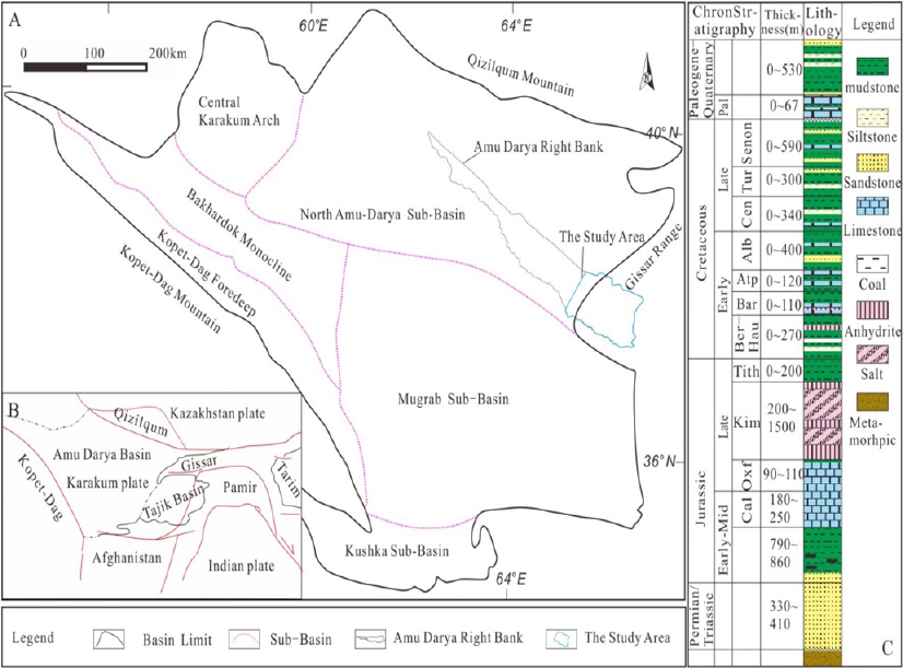
2 REGIONAL GEOLOGIC
SETTING
The Amu Darya Basin is situated within the Tethyan
tectonic domain, in the Karakum plate, and was
separated from the Tarim plate due to the Cenozoic
Alpine new tectonic movement (i.e., the Himalayan
movement) (Luo et al., 2005). The basin is bordered
to the north by the Qizilqum mountain, to the south
by the Kopet-Dag mountain, to the east by the
Gissar Range, and to the west by the Central
Karakum Arch(Figure 1). It is a Meso-Cenozoic
foreland basin formed on a Permian-Triassic rift and
has gone through three major stages: the Permian-
Triassic rifting, Jurassic-Paleogene depression and
Neogene compression (Natal'In et al., 2005;Golonka,
2004).
Figure 1: (A)Location map of the study area. (B)The tectonic unit map of Amu Darya Basin. (C)Stratigraphic chart for the
study area (Modify from Ulmishek G F
(Ulmishek, 2004), 2004 and Thomas J,1999
(Thomas et al., 1999)).
IWEG 2018 - International Workshop on Environment and Geoscience
240
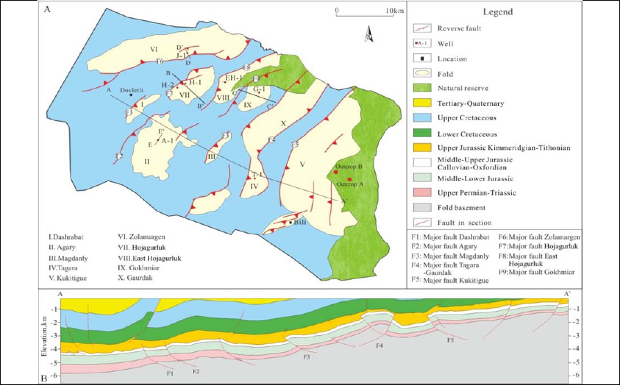
Figure 2: (A)Major geological structures (faults, folds) of the Callovian-Oxfordian carbonate. (B) C geological cross-
section showing the structural framework. For position see the map A.
The eastern of the Amu Darya Right Bank is
located in the northeastern part of the basin,
covering the Gissar Range and its piedmont. From
the Permian to Triassic, the Paleo-Tethys Ocean
expanded and the study area was under an
extensional environment, which enabled formation
of a 400 m thick sandstone-dominated transitional
stratum. Since the Jurassic, the stable depression
sedimentation period begun, allowing for deposition
of the Middle-Lower Jurassic coal-bearing clastic
rock(thickness 790-860m), Callovian-Oxfordian
carbonate rock(thickness 270-360m),
Kimmeridgian-Tithonian salt-gypsum
rock(thickness 200-1500), Cretaceous marine clastic
and carbonate rocks(thickness 560-2100m), and the
Paleogene clastic rock(thickness 0-600m), with the
maximum thickness of 5000 m(Figure 1). As a result
of the collision between the Indian and Eurasian
plates during Neogene, the Pamirs Plateau and
Gissar Range was uplifted. And the east of study
area eroded (Figure 2-B).
The Middle-Lower Jurassic coal-bearing clastic
rock, Callovian-Oxfordian carbonate rock and
Kimmeridgian salt-gypsum rock constitute a high-
quality source-reservoir-cap assemblage, with the
pre-salt Callovian-Oxfordian carbonate rock being
the primary target layer for exploration. By
comparing the thermal history of the source rock in
the Murgab sub-basin with the burial and thermal
history of the central part of the Amu Darya Right
Bank (Nie et al., 2017), it is found that in the study
area, the common burial depth of the source rocks in
the lower section of the Middle-Lower Jurassic
strata reached up to 4000 m towards the end of the
Paleogene, with the ancient formation temperature
of about 120℃, indicating the source rocks had
entered the peak hydrocarbon generation stage.
During Neogene, the east of the East Hojagurluk-
Tagara uplifted greatly and the Middle-Lower
Jurassic source rocks uplifted to a depth of less than
2200 m; and to the west, source rocks in the
piedmont area were further buried to a depth of 4500
to 5000 m, with formation temperature exceeding
160℃, and some areas entered the condensate-wet
gas stage (Fang et al., 2014). By Comparing the well
H-2 and T-1, in the east of the study area the
maximum burial depth of the carbonate rock ranged
from 3000 to 3500 m, in the west 3500 to 4000 m
Effect of Thrust Structural Pattern on Carbonate Reservoir and Gas Reservoir Type in the East of Amu Darya Right Bank
241
(Li, 2015). In the east actual measured formation
temperature of well G-1 in the Callovian-Oxfordian
carbonate rock is only 60℃, and in the west from
110 to 130℃ of the wells A-1, H-2 and J-1.
3 FAULT FEATURES AND
STRUCTURAL STYLE
The study area consists of pre-salt and post-salt
structural systems, divided by the salt-gypsum rock
bed. This study targeted the pre-salt thrust system
formed as a result of the collision between the
Indian and Eurasian plates.
3.1 Fault Features
Profile shows that, faults in the pre-salt structure
system are mostly shovel-like thrust faults, which
detach from the Paleozoic basement and pinch out in
the Upper Jurassic salt-gypsum rock bed (Figure 2).
The reverse faults are quite complex on the plane,
trending NEE, NE and nearly SN. The NEE-
trending faults are present in a limited area, as the
product of reformation of the Permian-Triassic
normal faults during the Neogene, such as the
Zolamargen fault. The NE-and SN-trending faults
take majority, which often intersect to form the arc-
shaped thrust faults that control the development of
folds. These faults were formed during the Neogene.
3.2 Structural Style
According to the thrust fault-related fold theory, the
pre-salt compressional structures can be divide into
two types: the fault-bend fold and breakthrough
fault-propagation fault.
The fault-bend fold is the fold formed by thrust
geologic body slipping along the fault surface and
deforming kink-line (Jia et al., 2002) In the study
area fault-bend folds are characterized by very short
front wing, long back wing and the axis in close
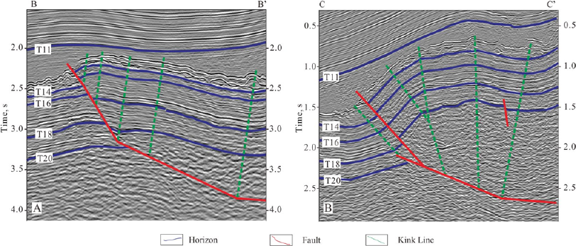
proximity to the main fault. A typical example is the
Hojagurluk structure(Figure 3-A), which is
controlled by a NE-trending fault, and shovel-like
on profile. This fault detaching into the basement
and pinching out in the post-salt strata, has
controlled the development of the fault-bend fold in
hanging wall. The fold high is close to the main fault.
Multiple fault-bend folds are present to the south of
the Hojagurluk fold, forming a thrust imbricated fan.
The primary fault propagates along the axis of
the front wing of the fault-propagation fold, giving
rise to the breakthrough fault-propagation fold
(Shaw et al., 2008). There are various shapes of
breakthrough fault-propagation folds, including
symmetrical and box-shaped ones. The fold high is
far from the main fault. A typical example is the
Gokhmiar fold (Figure 3-B), which is controlled by
a NE-trending, detaching into the basement, and
pinching out in the Kimmeridgian salt-gypsum
layers. This fold has symmetrical geometry, and fold
high far from the main fault Gokhmiar.
Figure 3: (A) Sesmic section of the fault-bend fold Hojagurluk. (B) Sesmic section of the breakthrough fault-
propagation fold Gokhmiar. For positions see the Figure2. (T11: Top of the Kimmeridgian salt-gypsum rock,
T14: Top of Callovian-Oxfordian carbonate rock; T16: Base of Callovian-Oxfordian carbonate rock, T18: Base
of Middle-Lower Jurassic coal-bearing clastic rock, T20: Top of basement).
IWEG 2018 - International Workshop on Environment and Geoscience
242
4 CONTROL OF STRUCTURAL
STYLE ON RESERVOIR
DEVELOPMENT
The study area was a low-energy sedimentary
environment with less-developed reef-shoal facies in
the Callovian-Oxfordian period (Xu et al., 2012).
The carbonate reservoirs include fracture type,
fracture-pore type and fracture-cave type. Structural
pattern has significant influence on reservoir
development.
4.1 Control of Structural Pattern on
Fracture
After surveying the field outcrops A and B in the
study area (Figure 2), the fracture in the Callovian-
Oxfordian carbonate rock development
characteristics of two typical thrust structural
patterns selected were investigated.
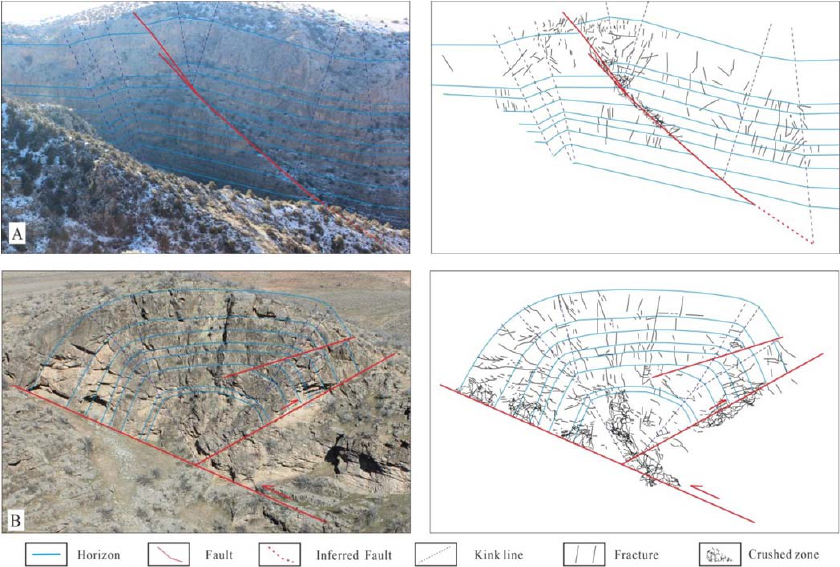
Control of fault-bend folds on fractures: fractures
are present primarily in the proximity of fold axis,
near the primary fault, and include two types: fault
fissures and extensional fold fissures, which form a
complex fracture system by intersecting with each
other. In areas far from the primary fault, fractures
become less dense apparently and are distributed
mainly within the kink band, and there are a few
stratal detaching fissures in the fold wings. In the
back wing of the fold where there is no bended
deformation, regional structural fractures take the
majority. There is a crushed zone in the local area of
stress concentration, near the primary fault (Figure
4-A).
Control of breakthrough fault-propagation folds
on fractures: fractures are present mainly in fold
wings. The closer to the primary fault, the more
density of fracture; a crushed zone occurs in the
local area of stress concentration; the fractures are
predominately fault fissures parallel to the fault
strike. High-angle extensional fold fissures are
present in the structural axis or bend position of
strata, but much lower in density than in the
proximity of the fault (Figure 4-B).
Figure 4: (A)Fracture distribution of the fault-bend folds in carbonate outcrop area. (B) Fracture distribution of the
breakthrough fault-propagation fold in carbonate outcrop area. For positions see the Figure 2. The strata in the
folds are the Callovian-Oxfordian carbonate rocks.The field photos are provided by Dr. Zhang Xingyang.
Effect of Thrust Structural Pattern on Carbonate Reservoir and Gas Reservoir Type in the East of Amu Darya Right Bank
243
By comparing the above folds, it is found that
they all have fractures mostly in the proximity of the
primary fault. The fault-bend fold has much higher
fracture density at the axis than the fault-propagation
fold, but lower fracture density in the wings.
4.2 Control of Faults on Dissolution
Scale
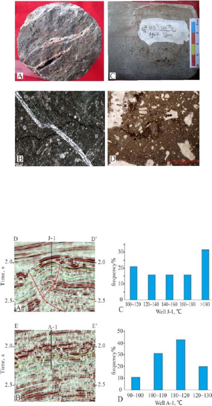
Lab analysis and microscopic observation of cores
recovered from wells reveal strong dissolution in the
Callovian-Oxfordian carbonate rock in the study
area along fractures and pores (Figure 5). Typical
dissolution actions include the deep-part
hydrothermal dissolution, thermochemical sulfate
reduction (TSR) and dissolution by acidic formation
fluid made up of organic acid (Zheng et al.,
2012;Zheng et al., 2010;Wen et al., 2010;Deng et al.,
2011). The deep-part hydrothermal fluid migrated
along fractures into the carbonate rock was more
conducive to the formation of dissolved pores, caves
and fractures. Typical examples include Well J-1 in
the Zolamargen and Well A-1 in the Agary.
Well J-1 is in close proximity to the main fault in
the Zolamargen fold. The reservoirs encountered are
fracture-cave type, and cores recovered reveal strong
dissolution along fractures. This well was tested
1.18 million cubic meters gas per day. Static and
dynamic data disclose that, there are two types of
dissolution fluids: ① organic matter retained in
fractures suggests the dissolution fluid may be
formation fluid containing organic acid; and ②
high-temperature deep-part hydrothermal fluid or
hot brine might be the dissolution fluid, which
migrated from the deep layer into the carbonate
rocks and caused strong dissolution to fractures,
since the fluid inclusions contained in the samples of
calcites filled in fractures have pressure-corrected
homogeneous temperatures of 160 to 200℃(Figure
6-A and C), significantly higher than the formation
temperature (130-150℃) of the carbonate rock in
Murgab, the deepest depression within the basin (Jia
et al., 2002), and the carbonate rock and the Middle-
Upper Jurassic source rock in the study area.
Figure 5: (A) Dissolved cave formed along fracture of
well J-1, semi-filled with calcite. (B) Partially-filled
fracture of J-1, impregnated by organic. (C) Grey clotted
sand-size grains of well A-1, with dissolved pores. (D)
Fracture full-filled with organic matter of A-1.
Figure 6: (A) and (B) respectively showing the seismic
profiles through Well J-1 and A-1. For position see the
Figure 2-A. (C) and (D) respectively showing the
homogenization temperature histogram of fluid inclusions
of Well J-1 and A-1. The data is provided by Dr. Ma
Wenxin.
Well A-1 is located at high of the Agary. The
reservoirs encountered in this well are fracture-pore
type with weak dissolution, and was tested
6×10
4
m
3
/d. Static and dynamic data indicate that
there are two types of dissolution fluids: ①
formation fluid containing organic acid might be the
dissolution fluid, as organic matter is retained in
fractures; and ② acidic formation fluid resulted
from TSR-generated H
2
S and CO
2
dissolving in
IWEG 2018 - International Workshop on Environment and Geoscience
244
formation water might be the dissolution fluid, since
the natural gas produced has a H
2
S content of 0.02
to 0.04%, much higher than Well J-1 (0.0008%-
0.007%). Whereas deep-part hydrothermal fluid
might exert a weak dissolution to the carbonate
reservoir, since the fluid inclusions contained in the
samples of calcites filled in fractures have the
homogeneous temperatures of 100 to 120℃, which
are basically consistent with the formation
temperature(Figure 6-B and D).
By comparing the locations of these wells on
fold, it is revealed that the primary fault has a strong
control over the dissolution to fractures: in areas
adjacent to the primary fault, the deep-part
hydrothermal fluid acts as the primary dissolution
fluid, which has strong dissolution to fractures; and
in areas far from the primary fault, the mixed
organic acid and the acidic formation fluid resulted
from TSR are major dissolution fluids, which have
weak dissolution to fractures.
4.3 Control of Structural Pattern on
Reservoir Type
It is concluded through analysis of fracture
distribution and dissolution that structural style has a
significant influence on distribution of fracture
/fracture-pore type and fracture- cave type reservoirs.
The axis of the fault-bend fold is close to the
primary fault, where fractures were well-developed
and strong deep-part hydrothermal dissolution
occurred, allowing for formation of fracture-cave
type carbonate reservoir; and in the back wing of
this type of fold, where fractures are less and the
dissolution fluid dominated by acidic formation
fluid enabled weak dissolution, the reservoirs are
largely fracture or fracture- pore type ones.
The axis of the breakthrough fault-propagation
fold is far from the primary fault, where fractures are
less common and dominated by high-angle fold
fissures, and acidic formation fluid acts as the
primary dissolution fluid, so fracture or fracture-
pore type reservoirs occur; in the front wing of this
type of fold close to the primary fault, there are
dense fault fissures are and strong dissolution, so
fracture-cave type reservoirs developed; and in the
back wing of the fold, reservoirs are largely fracture
or fracture- pore type, similar to the structural high.
5 CONTROL OF STRUCTURAL
STYLE ON GAS POOL TYPE
The Middle-Lower Jurassic coal-bearing clastic rock
in the Amu Darya Basin reached hydrocarbon-
generation threshold at the Late Cretaceous, and
entered hydrocarbon generation peak at the
Paleogene time, producing massive natural gas
(Wang et al., 2012). The Neogene Himalayan is a
critical period for trap formation, reservoir quality
enhancement and hydrocarbon accumulation in the
eastern part of the block. Traps begun to occur in
Miocene and finalized in shape in Pleistocene. The
pre-salt NE-trending thrust faults formed under the
Himalayan compression acted as the pathways for
hydrocarbon migration, which enabled the vertical
migration of hydrocarbon along faults towards the
carbonate rock and the areal migration along faults
from the hydrocarbon-generating depression to the
uplift zones. Structural highs adjacent to faults are
favorable places for hydrocarbon accumulation,
particularly the fracture- cave type reservoir zones
formed as a result of tectonic disruption and
dissolution, are possible sites of high-productivity
fracture-cave type gas pools.
Highs of the fault-bend folds are considered
favorable areas for development of fracture-cave
type gas pools(Figure 7), which are highly charged
with natural gas and have low water/gas ratio.
Exploration wells in this type of gas pool are usually
tested over a million cubic meters of gas per day.
Wings of the fault-bend folds are far from the
primary fault and hence may receive less
hydrocarbons. Usually, these areas have fracture or
fracture-pore type gas pools, which are less gas-
charged, have high water/gas ratio, and low single-
well gas production. Therefore, vertical wells on
structural highs can achieve high production with
lower drilling costs; while it is recommended to drill
deviated wells in back wings with well trajectory
parallel to the strike of fold as far as possible, for the
purpose of encountering more regional conjugated
structural fissures and enhancing the well production.
For example, vertical wells were drilled in axis of
various folds, such as Hojagurluk, West Zolamargen
and Dashrabat. In Hojagurluk Well H-2 was tested
at a million cubic meters of gas per day, with no
formation water produced from the entire carbonate
rock interval.
Effect of Thrust Structural Pattern on Carbonate Reservoir and Gas Reservoir Type in the East of Amu Darya Right Bank
245
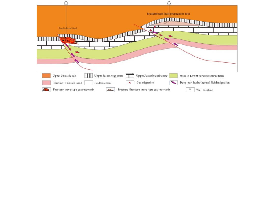
Figure 7: Patterns of gas reservoirs formation and well trajectory suggestions in different folds.
Table 1: Patterns of key folds and well-testing data ( The data is provided by manager Laiyong Cao)
Name of fold Fold type
Gas pool
type
Well type
Distance
to fault
Tested
production
(10
4
m
3
d
-1
)
Water/Gas ratio
(g 10
-4
m
3
)
Gokhmiar
Breakthrough fault-
propagation fold
Fracture Vertical 4.5km 30 18-56
Tagara
Breakthrough fault-
propagation fold
Fracture Vertical 3.5km 36 14
East
Hojagurluk
Breakthrough fault-
propagation fold
Fracture-
pore
Deviated 2km 85 13-16
Zolamargen
Breakthrough fault-
propagation fold
Fracture-
pore
Vertical 4km 62 17
West
Zolamargen
Fault-bend fold
Fracture-
cave
Deviated 0.33km 101 9-11
Hojagurluk Fault-bend fold
Fracture-
cave
Vertical 1.1km 117 4-7
There develop fracture-cave type reservoirs in
areas adjacent to the primary fault in breakthrough
fault-propagation folds. However, formation of gas
pools seems unlikely, since the structural position is
too low to provide effective traps. In structural highs
of the breakthrough fault-propagation folds that are
far from the gas-source fault and went through weak
fracturing and dissolution, fracture or fracture-pore
type gas reservoirs were formed(Figure 7). In
addition, these reservoirs have poor original physical
properties, are less gas-charged and hence yield low
tested gas production. The larger the distance to
fault, the higher the water/gas ratio will be. Typical
example include the A-1 well of the Agary Gas
Field. Its carbonate reservoir is fracture-pore type
(Liu et al., 2012), the tested production is 6×10
4
m
3
/d,
and the water/gas ratio is reached 200g/10
4
m
3
. As
for this type of fold, it is recommended to deploy
deviated wells on high with well trajectory
perpendicular to the strike of the fold, for the
purpose of encountering more fold fissures and
enhancing the single-well production. In the Tagara,
Gokhmiar and East Hojagurluk folds, for example,
deviated wells drilled on structural highs yielded
much higher gas production than vertical wells. In
addition, the water/gas ratio of a well is dependent
directly upon the distance to the primary fault; that
is, the larger the distance to fault, the higher the
water/gas ratio will be.
Unfortunately, drilling deviated wells based on
geological understandings may not be possible for
some folds, due to the national policy restriction.
The tested production data of wells collected from
the discovered gas fields proved the forecasted
development characteristics of gas pools in different
structural patterns (Table 1).
IWEG 2018 - International Workshop on Environment and Geoscience
246
6 CONCLUSIONS
(1) There are two types of thrust structural styles in
the pre-salt strata in the study area: i.e., the fault-
bend fold and breakthrough fault-propagation fold.
In the axis of fault-bend folds close to the primary
fault, fractures are dense and several groups of
fractures intersect, but in back wings of the folds
there are less fractures. As for the breakthrough
fault-propagation folds, there are more fractures in
the front wing than the axis, and fractures in the axis
are largely high-angle fold extensional fissures.
(2) Deep-part hydrothermal fluids migrated
upwards along the primary fault of the fold
delivered strong dissolution to fractures and pores.
As a result, fracture-cave type reservoirs tend to
form in axis of fault-bend folds and front wing of
breakthrough fault-propagation folds, and fracture-
pore type reservoirs are likely to form in back wing
of fault-bend folds and pore-fracture type reservoirs
in axis and back wing of breakthrough fault-
propagation folds.
(3) With fracture-cave type reservoirs and close
to gas source fault, structural highs of fault-bend
folds are favorable positions for high-production
fracture-cave type gas pools, which have high tested
production of wells and low water/gas ratio. In
structural highs of breakthrough fault-propagation
folds that are far from the gas source fault, where
weak fracturing and dissolution occurred, fracture or
fracture-pore type gas pools could occur, with low
tested production; and the larger the distance to the
fault, the higher the water/gas ratio will be.
(4) Vertical drilling is recommended for the axis
of fault-bend folds, where fracture-cave type gas
pools may present. Deviated drilling is
recommended for the back wing of fault-bend folds,
where fracture-pore type gas pools are present.
Deviated drilling perpendicular to the strike of
primary fault is recommended for the axis of
breakthrough fault-propagation folds, where
fracture-pore type gas pools are present. Defining
the development model of gas pools in different
structural patterns is helpful to quickly discover the
gas fields in the study area.
ACKNOWLEDGMENTS
This study is funded by government through its
programs: the “Research and application of the key
technology for the efficient development of
fractured-porous carbonate reservoirs in the right
bank of Turkmenistan” and “Fine evaluation and
prediction technology of complex reservoir of
natural gas reservoir”. The fund numbers are
2017ZX05030-003 and 2018D-4305.
REFERENCES
Deng Yan, Wang Qiang, Cheng Xubin, Wu Lei, Zhao
Changcheng, Chen Renjin 2011 Origin and
distribution laws of H
2
S in carbonate gas reservoirs in
the Right Bank Block of the Amu Darya River
Natural Gas Industry 31 21-23
Fang Jie, Xu Shubao, Wu Lei, Ouyang Hua, Nie
Minglong 2014 Hydrocarbon Generation Potential of
Jurassic Source Rocks in Right Bank of Amu Darya
Marine Origin Petroleum Geology 19 8-18
Golonka J 2004 Plate tectonic evolution of the southern
margin of Eurasia in the Mesozoic and Cenozoic
Tectonophysics 381 235-273.
Jia Dong, Jia Chengzao 2002 Hydrocarbon migration and
accumulation behaviour in fault-bend folds and fault-
propagation folds Journal Of Nanjing
University(Natural Science) 38 747-755
Jin Chongtai 2012 Fault systems and reservoir-controlling
mechanism in Kelasu Thrust Belt of Kuqa basin
Northeast Petroleum University 123
Li Zhi 2015 Geologic structure and hydrocarbon
accumulation of eastern foreland in Amu Darya Right
Bank China University of Geosciences(Beijing) 137
Liu Shilei, Zheng Rongcai, Yan Wenquan, Liao Jun, Jiang
Hao, Wang Xiaoping 2012 Characteristics of
oxfordian carbonate reservoir in Agayry area, Amu
Darya Basin. Lithologic Reservoirs 24 57-63
Luo Jinhai, Zhou Xinyuan, Qiu Bin, Yang Zhiling, Yin
Hong, Li Yong, Li Jianli 2005 Petroleum Geology and
Geological Evolution of the Tarim-Karakum and
Adjacent Areas Geological Review 51 409-415
Mu Longxin 2017 Overseas petroleum exploration and
develepment characteristic technology and its
application Petroleum Industry Press 302
Natal'In B A, Şengör A M C 2005 Late Palaeozoic to
Triassic evolution of the Turan and Scythian platforms:
The pre-history of the Palaeo-Tethyan closure
Tectonophysics 404 175-202
Neng Yuan, Li Yong, Xu Lili, Zhou Peng, Wang Bin,
Shang Jiangwei, Cao Shujuan 2017 Patterns of
fracture zone in the deep subsalt layer of kelasu
structural belt and prospecting method Geotectonica et
Metallogenia 41 61-68
Nie Minglong, He Dengfa, Liu Qunming, Xu Shubao, Wu
Lei, Zhao Xinglin 2017 Evolution of Basement Faults
in the Northeastern Aym Dye Basin and Its Control on
the Hydrocarbon Migration-accumulation in Subsalt
Sequences Geological Journal of China Universities
23 277-284
Effect of Thrust Structural Pattern on Carbonate Reservoir and Gas Reservoir Type in the East of Amu Darya Right Bank
247
Nie Minglong, Wu Lei, Xu Shubao, Liu Bin 2013 Genetic
mechanism and exploration significance of tectonic
action in the Bieshikent Depression and its adjacent
area in the Amu-Darya Basin Natural Gas Industry 33
45-50
Shaw J H, Connors C, Zaap J 2008 Interpretation of
contractional fault-related folds. Petroleum Industry
Press 156
Shi Xin, Zhang Liping, He Dengfa, Du Shekuan, Wang
XuLong, Zhang ChaoJun, Guan ShuWei, Yang Geng
2005 The reservoir formation model in the
northwestern margin of junggar basin Natural Gas
Geoscience 37 944-951
Tang Ying, Fan Tailiang, Zhang Tao, Wang Zhe, Zheng
Yuanchao 2016 Influence of tectonic movement on
Cretaceous carbonate reservoirs in the Zagros
Foreland Basin:A case study of Y oilfield Oil & Gas
Geology 37 944-951
Thomas J, Grasso J, Bossu R, Martinod J 1999 Recent
deformation in the Turan and South Kazakh platforms,
western central Asia, and its relation to Arabia‐Asia
and India‐Asia collisions Tectonics 18 201-214
Ulmishek G F 2004 Petroleum Geology and Resources of
the Amu-Darya Basin, Turkmenistan, Uzbekistan,
Afghanistan, and Iran: U.S. Geological Survey
Bulletin 2201-A U.S. Geological Survey 32
Wang Haixue 2015 Research on hydrocarbon
accumulation of different structural belt the pre-
Jurassic strata in the Tainan Depression, Tuha Basin
Northeast Petroleum University 107
Wang Qiang, Cheng Xubin, Fei Huaiyi 2012 Reservoir
forming process of a block in the Right Bank of the
Amu Darya River Natural Gas Exploration and
Development 35 1-4
Wen Huaguo, Gong Boshi, Zheng Rongcai, Liu Henian,
Wu Lei, Chen Rejin, Li Shilin, Chen Shouchun 2010
Deposition and diagenetic system of carbonate in
Callovian-Oxfordian of Samandepe Gasfield,
Turkmenistan Journal of Jilin University(Earth
Science Edition) 42 991-1002
Xu Wenli, Zheng Rongcai, Fei Huaiyi, Sun Zijin, Wang
Qiang 2012 The sedimentary facies of Callovian-
Oxfordian Stage in Amu Darya basin, Turkmenistan
Geology in China 39 954-964
Yu Yixin, Yin J, Zheng J, Feng Li, Tao C, Xiaolong Xu
2015 Division and resources evaluation of
hydrocarbon plays in the Amu Darya Basin, Central
Asia Petroleum exploration and development 42 750-
756
Zhang Jiping, Bi Xinzhong, Gu Yongqiang 2010 The
status of oil and gas resources in Turkmenistan
Foreign oil field engineering 26 48-50
Zhao Chan 2011 Reservoir genesis and geochemical
characteristics of the carbonate rocks of Callovian-
Oxfordian Formation,Turkmenistan Chengdu
University of Technology 48
Zheng Rongcai, Liu Henian, Wu Lei, Chen Renjin, Shi
Jiannan, Li Fengjie 2012 Geochemical characteristics
and diagenetic fluid of the Callovian-Oxfordian
carbonate reservoirs in Amu Darya basin Acta
Petrologica Sinica 28 961-970
Zheng Rongcai, Zhao Can, Liu Henian, Wu Lei, Chen
Renjin 2010 Cathodoluminescence and its significance
of the Callovian-Oxfordian carbonate rocks in Amu
Darya basin, Turkmenistan Journal of Chengdu
University of Technology(Science & Technology
Edition) 37 377-385
IWEG 2018 - International Workshop on Environment and Geoscience
248
