
Experimental Research on the Directivity of Overhauser
Magnetometer
Xue Jiang
1
, Shudong Chen
1
, Shuang Zhang
1*
and Xin Guo
2
1
College of Electronic Science and Engineering, Jilin University, Changchun City, Jilin Province, China
2
College of physics, Jilin University, Changchun City, Jilin Province, China
jiangxue470@163.com, chenshudong@jlu.edu.cn, zhangshuang@jlu.edu.cn, guoxin@jlu.edu.cn
Keywords: Overhauser magnetometer, sensor,
directivity, sensitivity.
Abstract: Overhauser magnetometer with the advantages of high sensitivity and low power consumption is widely
used in different fields. As an important part of the system, the sensor is responsible for the performance of
the whole system. In this paper, the influences of sensor orientation on the performance of Overhauser
magnetometer are investigated. The Larmor signal and the system sensitivity have been measured and
analyzed when sensor in different directions. The experimental results show that the JOM-3 magnetometer
sensor has no dead zone but poor omnidirection. Factors affected directivity of the sensor are discussed in
this paper.
1 INTRODUCTION
Overhauser magnetometer, based on dynamic
nuclear polarization (DNP) effect, is widely used in
volcano surveillance, mineral prospecting ,
geophysical exploration, weapons detection and arch
eology (Duret,1995). Compared to the traditional
proton precession magnetometer, Overhauser
magnetometer can achieve higher sensitivity with
lower power consumption, (Maly,2008). The
sensitivity of the Overhauser magnetometer GSM-19
made by GEM reaches up to 0.015-0.022nT and
power consumption as low as 2W. Overhauser
magnetometer researched by Zhang Shuang and
other scholars has also made great progress
(Ge,2016).
After a long period of research, we have
developed a series of Overhauser magnetometers,
the newly one is named JOM-3 Overhauser
magnetometer. Compared with the JOM-2
Overhauser magnetometer, the system sensitivity
has been improved by optimizing the design of the
preamplifier circuit (Zhang,2017). With the new
digital architecture of ARM + CPLD in the JOM-3
Overhauser magnetometer, the frequency
measurement is more accurate and power
consumption is reduced (Fan,2016
).
Sensitivity is an important parameter to evaluate
the performance of the instrument. It indicates the
repeatability of the instrument measurement. In
addition, the sensitivity of the magnetometer system
can be affected by many factors, such as signal-to-
noise ratio, frequency measurement accuracy and
surrounding environment (Hovde,2013). The
influences on the instrument performance caused by
the sensor orientation will be investigated in this
paper.
2 PRINCIPLE OF OPERATION
Overhauser magnetometer sensor is filled with free
radical solution. In the absence of external field, the
hydrogen proton orientation is random, total
magnetic moment is zero. In the geomagnetic field,
randomly oriented proton magnetic moments are
oriented along the geomagnetic field, and the total
magnetic moment is M0, as shown in Fig.1(a). With
the radio frequency excitation, the phenomenon of
the double resonance of electrons and nuclei occurs
in solution, and the total magnetic moment M1 has
been greatly enhanced on geomagnetic field
direction, as shown in Fig.1(b). In the presence of
DC polarization field, the total magnetic moment
M2 deflects away from the geomagnetic field, as
shown in Fig.1(c). After the DC signal is turned off,
total magnetic field revert to geomagnetic field, and
560
Jiang, X., Chen, S., Zhang, S. and Guo, X.
Experimental Research on the Directivity of Overhauser Magnetometer.
In 3rd International Conference on Electromechanical Control Technology and Transportation (ICECTT 2018), pages 560-563
ISBN: 978-989-758-312-4
Copyright © 2018 by SCITEPRESS – Science and Technology Publications, Lda. All rights reserved
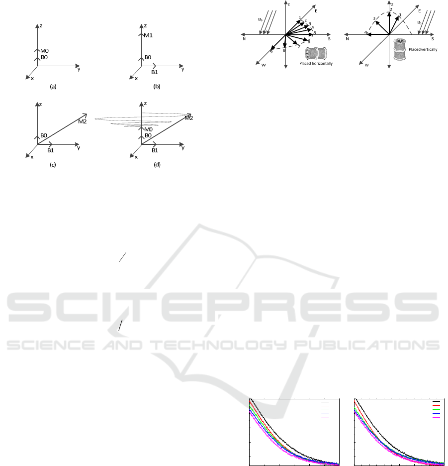
the hydrogen proton will rotate around direction of
geomagnetic field to M0, as shown in Fig.1(d).
Figure 1: Principle of Overhauser magnetometer.
In the procession to the geomagnetic field,
magnetic moment cutting receiving coils. The
Larmor signal induced in the coils can be expressed
as:
00
() sin
t
T
Vt A e t
(1)
Where ω
0
is Larmor frequency, T is the time
constant of signal attenuation. Larmor signal
frequency is proportional to the magnetic field
strength:
0
2
p
fB
(2)
Where f is the Larmor frequency of the proton
precession signal, γ
p
is the gyromagnetic ratio and
the value is 2.67512×10
8
T
-1
S
-1
, B
0
is the magnitude
of the external magnetic field. Magnetic field
strength can be expressed as:
0
23.4874BT zn
f
H
(3)
Therefore, the magnetic field strength can be
calculated by measuring the frequency of the Larmor
signal.
3 EXPERIMENTAL RESULTS
3.1 Experimental program
Two sets of experiments are designed to study the
directivity of the sensor in this paper. Direction of
the geomagnetic field in Changchun, Jilin Province,
is vertical to the south 30 degrees pointing to the
ground. Considering that the experiments are carried
out in both horizontal and vertical planes.
(a) (b)
Figure 2: (a) Schematic of direction in horizontal plane, (b)
Schematic of direction in vertical plane.
As shown in Figure 2(a), nine directions
numbered 1-9 were set from east to west for
experiment in the horizontal plane. The nine
directions are the east direction, 20 degrees east to
south, 40 degrees east to south, 60 degrees east to
south, south direction, 20 degrees south to west, 40
degrees south to west, 60 degrees south to west and
west direction. As shown in Figure 2 (b), four
directions numbered 1-4 were set for experiment in
the vertical plane. The four directions are the
geomagnetic field direction, the vertical direction,
vertical 45 degrees north direction and the north
direction, respectively.
3.2 Effect of Sensor Orientation on the
Larmor Signal
3.2.1 Experimental results when sensor in
horizontal plane
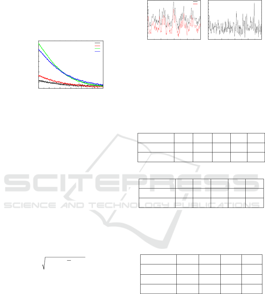
When sensor is placed in different directions as
shown in Figure 2(a), the envelopes of the Larmor
signals received are shown in Figure 3.
0123
0.5
1.0
1.5
2.0
2.5
amplitude/V
t/s
1
2
3
4
5
0.0 0.5 1.0 1.5 2.0 2.5 3.0
0.5
1.0
1.5
2.0
2.5
amplitude/V
t/s
9
8
7
6
5
(a) (b)
Figure 3: (a) The test resaults when sensor in direction
numbered 1~5, (b) The test resaults when sensor in
direction numbered 5~9.
It can be seen from Figure 3 that the amplitude of
the Larmor signal is largest up to 2.50V when the
sensor is placed in east direction and west direction.
As the sensor's major axis approaches the south, the
amplitude of the Larmor signal decreases. When the
sensor is placed in the south direction, the amplitude
of the signal is the smallest, as low as 2.03V.
Experimental Research on the Directivity of Overhauser Magnetometer
561
3.2.2 Experimental results when sensor in
vertical plane
When sensor is placed in different directions as
shown in Figure 2(b), the envelopes of the Larmor
signals received are shown in figure 4.
0.0 0.5 1.0 1.5 2.0 2.5 3.0
0.5
1.0
1.5
2.0
2.5
amplitude/v
t/s
1
2
3
4
Figure 4: Test resaults when sensor in vertical plane.
It can be seen from Figure 4 that the amplitude of
the Larmor signal is the smallest as low as 0.57V
when the sensor is placed in direction 1. Direction 1
represent the direction of the geomagnetic field in
Changchun. In the other three directions, the
amplitude of the Larmor signal gradually increases,
when the angle between the sensor's major axis and
the geomagnetic field increases.
3.3 System sensitivity
3.3.1 System sensitivity experiment
The sensitivity of a magnetometer is expressed by
the standard deviation of multiple measurements. In
this experiment, two sensors are placed in the same
direction with a spacing of 1.5m and perform their
measurements at the same time. The relative
uncertainty of the two sensors is taken as the
sensitivity of the instrument, expressed as:
1
()/(2)
N
i
i
XXN
(4)
Where ΔX
i
is the difference between the ith
measurements of the two sensors and ΔX is the
difference between the mean values of the N
measurements of the two sensors.
In this measurement, the cycle time is set to 3s
for 30 minutes, and the middle 200 groups of data
are taken for sensitivity calculation. Take the
direction 1 in the horizontal plane as an example, the
measurement results when sensor is placed in
direction 1 are shown in figure 5. According to Eq.
(4), the sensitivity reaches 0.07nT. When the sensor
is placed in other directions, the sensitivity is still
calculated by this method.
0 150 300 450 600
54040
54060
54080
54100
54120
54140
54160
B/nT
t/s
B1
B2
0 150 300 450 600
-0.2
-0.1
0.0
0.1
0.2
0.3
0.4
B/nT
t/s
(a) (b)
Figure 5: (a) Magnetic field intensity, (b) Differences of
two sensors.
3.3.2 Analysis of system sensitivity
The signal amplitude and system sensitivity
measured when sensor in 9 directions in the
horizontal plane are listed in Table 1.1 and Table 1.2:
Table 1.1: Experimental data when sensor in position 1~5.
Direction 1 2 3 4 5
Amplitude/V 2.50 2.40 2.27 2.13 2.03
Sensitivity/nT 0.07 0.08 0.08 0.08 0.09
Table 1.2: Experimental data when sensor in position 5~9.
Direction 5 6 7 8 9
Amplitude/V 2.03 2.09 2.18 2.43 2.50
Sensitivity/nT 0.09 0.08 0.08 0.08 0.08
The signal amplitude and system sensitivity
measured when sensor in 4 directions in the vertical
plane are listed in Table 2:
Table 2: Experimental data when sensor in vertical plane.
Direction 1 2 3 4
Angle/゜
0 30 75 60
Amplitude/V 0.57 0.80 2.38 2.05
Sensitivity/nT 0.18 0.16 0.08 0.10
According to Table 1.1, Table 1.2 and Table 2,
system sensitivity and signal amplitude are affected
by the angle between the major axis of the sensor
and the geomagnetic field. The larger the angle, the
higher the sensitivity is.
When the major axis of the sensor is
perpendicular to geomagnetic field, the amplitude of
Larmor signal and the sensitivity can reach 2.50V
and 0.07nT, respectively.
ICECTT 2018 - 3rd International Conference on Electromechanical Control Technology and Transportation
562
4 DISCUSSION
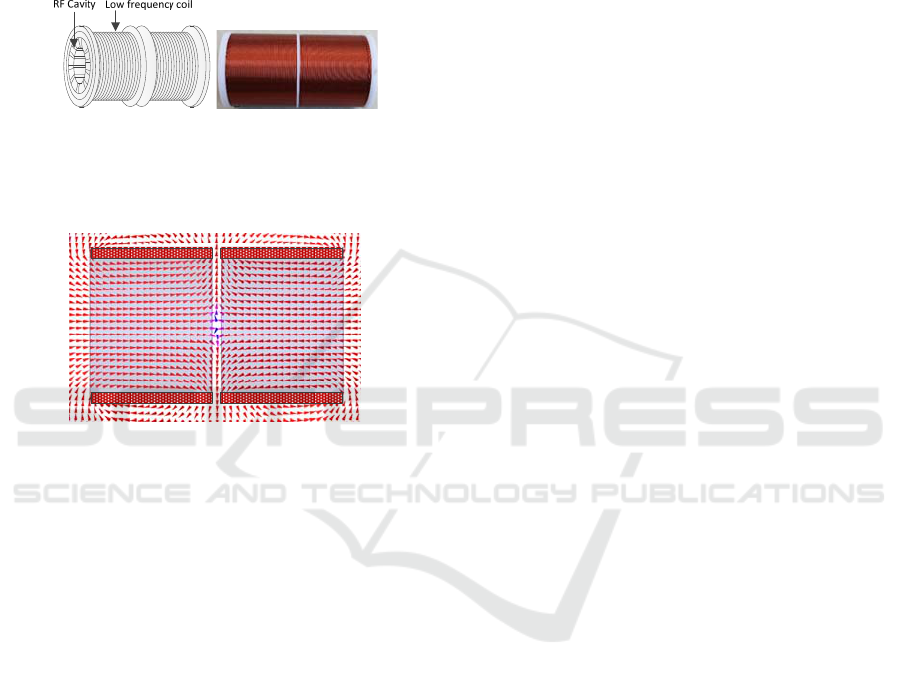
As shown in Figure 6, the sensor of Overhauser
magnetometer is composed of low frequency coil
and radio-frequency cavity. Low frequency coil is
made of a pair of reverse winding coaxial solenoids.
The radio-frequency cavity filled with free radical
solution is inside the low frequency coil.
(a) (b)
Figure 6: (a) Sensor structure, (b) Low frequency coil.
DC magnetic field inside the sensor is simulated
by Ansoft Maxwell software as shown in Fig.7.
Figure 7: Axial magnetic field distruibution.
It can be seen from Fig.7 that the DC
polarization field generated by the low frequency
coil is mainly parallel to the major axis of the coil.
According to the measurement, the sensor can
produce the Larmor signal with maximum amplitude
when the DC polarization field is perpendicular to
the geomagnetic field. Otherwise, the amplitude of
the Larmor signal will be reduced. At the edge of the
coil, the DC polarization field is perpendicular to the
major axis of the coil. When the sensor is parallel to
the geomagnetic field, the low frequency coil can
still induce the Larmor signal. However the signal is
weak and the system sensitivity is poor. The
distribution of the polarization field described above
is the key factor for the directivity of the sensor.
5 CONCLUSIONS
Factors affected directivity of sensor are discussed in
this paper. Considering the direction of Changchun
geomagnetic field is vertical to the south 30 degrees
pointing to the ground. The experiments are carried
out in both horizontal and vertical planes.
The experimental results indicate that when the
sensor is perpendicular to the geomagnetic field, the
signal amplitude and the sensitivity are both the
highest. When the sensor is parallel to the
geomagnetic field, the signal amplitude is the
smallest and the sensitivity is the lowest. According
to the simulation of low frequency coil, DC
polarization field inside the sensor is mainly parallel
to the major axis of the coil. But at the edge of the
coil, DC polarization field is perpendicular to the
major axis of the coil. All of these results reveal that
the direction of DC polarization field can effectively
influence the sensor's directivity. The sensor
discussed in this paper have no dead zones, but poor
omnidirection. An optimized low frequency coil
design with equal perpendicular and parallel
polarization magnetic fields will be investigated in
further study.
ACKNOWLEDGEMENTS
This work was supported by the National Natural
Science Foundation of China under Grant No.
61771218.
REFERENCES
Duret D, Bonzom J, Brochier M, et al. Overhauser
magnetometer for the Danish Oersted satellite[J].
IEEE Transactions on magnetics, 1995, 31(6): 3197-
3199.
Maly T, Debelouchina G T, Bajaj V S, et al. Dynamic
nuclear polarization at high magnetic fields[J]. The
Journal of chemical physics, 2008, 128(5): 02B611.
Zhang X, Jiang X, Zhao J, et al. Design and
implementation of JOM-3 Overhauser magnetometer
analog circuit[C]//Earth Observing Systems XXII.
International Society for Optics and Photonics, 2017,
10402: 104022D.
Fan S, Chen S, Zhang S, et al. An improved Overhauser
magnetometer for Earth's magnetic field
observation[C]//Earth Observing Systems XXI.
International Society for Optics and Photonics, 2016,
9972: 99721N.
Hovde D C, Prouty M D, Hrvoic I, et al. Commercial
magnetometers and their application[J]. Optical
Magnetometry, 2013: 387-405.
Ge J, Dong H, Liu H, et al. Overhauser Geomagnetic
Sensor Based on the Dynamic Nuclear Polarization
Effect for Magnetic Prospecting[J]. Sensors, 2016,
16(6): 806.
Experimental Research on the Directivity of Overhauser Magnetometer
563
