
Technical Development and Analysis of Four-Wheel Aligner for
Automobiles
Sheng Yu, Fuzhou Zhao
1
a
, Yunming Zhang and Xukai Huang
School of Mechanical Engineering, Ningbo University Of Technology,Ningbo, Zhejiang Province, China, 315211
1
Department of Automobile Engineering, Changshu Institute of Technology,Changshu, Jiangsu Province, China, 215500
{ xjz2020@163.com }
Keywords: Four-wheel aligner, technical development, automobile.
Abstract: The development status of four-wheel aligner for automobiles is reviewed in this paper at first. Then the key
technology of developing four-wheel aligner is analyzed. Measuring Datum and positioning mode are the
base of the aligner model. Measuring principle and its theoretical error are illustrated to enhance the
measurement accuracy. Finally this paper gives an outlook to the research of four-wheel aligner.
1 INTRODUCTION
Vehicle wheel alignment parameters which mainly
include the kingpin inclination angle, the caster
angle, the camber angle, the toe-in angle and the
thrust angle reflect the relative position relation
between wheel, steering knuckle and front/rear axle.
They have important influence on vehicle's handling
stability. According to the design requirements, the
wheel alignment parameters need to be adjusted in
advance, but they will change after a period of
driving. Wheel positioning angle deviation from the
design value will result in a series of adverse
consequences such as abnormal tire wear, fuel
consumption increase, and even the car steering
difficulties and path offset. As a special equipment
for detecting wheel alignment parameters, the four-
wheel aligner plays an important role in vehicle
maintenance and fault detection.
2 DEVELOPMENT STATUS OF
FOUR-WHEEL ALIGNER
With the continuous improvement of the accuracy
requirements of the wheel alignment parameters in
modern automobile performance testing, the
research of four-wheel aligner has been flourishing.
At present, there are two kinds of measurement
methods for four-wheel aligner used at home and
abroad, static measurement and dynamic
measurement. Static measurement refers to the mode
of detecting the vehicle wheel alignment in the
stationary state according to the geometrical relation
of the reference point on the center of the wheel. The
equipment with this mode mainly includes leveling
wheel aligner, pull-line wheel aligner, laser wheel
aligner and CCD wheel aligner. The leveling wheel
aligner is simple in structure and easy to carry, but it
has low precision and can not measure the toe-in
angle and the thrust angle. The typical levelling
wheel aligner such as Japan's 900A, WAT2000 and
domestic GCD-I, and is only suitable for the
detection of the front wheel about non-independent
suspension trucks (XU Guan, 2009). The pull-line
wheel aligner adopts the micro-computer to control
the angular displacement sensor to analyze the data,
and then realizes the visual display of the data.
However, the operation complexity and low
precision are still its main drawbacks (LV Xiaojun,
2011). Laser wheel aligner adopts the cooperation of
the lasers and wheel mounted jigs to capture signals.
It can neither be used to accurately measure nor
rapidly detect because of the narrow beam and the
limited range, therefore laser wheel aligner has been
abandoned in the developed countries of the
automotive industry. As an advanced wheel aligner,
CCD wheel aligner integrates with a new type of
semiconductor integrated optoelectronic device,
which makes it wide utilization and high precision.
Whereas there are also disadvantages such as high
manufacturing cost and complex maintenance (DAI
Renqiang, 2013). At present, this type of wheel
aligner manufacturers mainly include HUNTER,
Yu, S., Zhao, F., Zhang, Y. and Huang, X.
Technical Development and Analysis of Four-wheel Aligner for Automobiles.
In 3rd International Conference on Electromechanical Control Technology and Transportation (ICECTT 2018), pages 555-559
ISBN: 978-989-758-312-4
Copyright © 2018 by SCITEPRESS – Science and Technology Publications, Lda. All rights reserved
555

JBC, BEISSBATH, CORCHID, Three Jay Yi , and
so on.
Dynamic measurement refers to the method of
measuring the vehicle wheel alignment in the
moving state. The toe-in angle, track width, the
wheelbase and the inclination angle are all directly
when the vehicle is driving while they are distorted
in the stationary state, which are influenced by many
factors such as rim distortion, chassis clearance,
suspension deformation and heavy load. Thus, the
dynamic measurement becomes the mainstream
measurement method with higher precision. The 3D
wheel aligner is one of the most widely used
measurement equipment in the market, which is
attributed to its use of three-dimensional dynamic
measurement and the fast algorithm to achieve a
qualitative leap in principle, precision and real-time,
such as the JBC-V3D of the United States, the
German BOSCH-FWA4510, etc. The device has
many advantages such as high measurement
efficiency, accurate measurement and low failure
rate.
3 KEY TECHNOLOGY OF
DEVELOPING FOUR-WHEEL
ALIGNER
3.1 Measuring Datum and Positioning
Mode
There are two important rotating axes that affect the
four-wheel alignment, the steering axis of steering
wheel when turning and the rolling axis of the
wheel. Among them, the kingpin inclination angle
and the caster angle are the two-dimensional angle
of the steering axis, the camber angle and the toe-in
angle are two dimensional angles of the rolling axis
(ZHANG Mei, 2008). In addition, the four-wheel
positioning datum also comprises a OXY plane of
vehicle coordinate system, a geometrical centreline
and a thrust line.
The OXY plane refers to a plane formed by the
center of the front and rear axles, and the thrust line
is an imaginary line obtained from the intersection
of the two rear wheels plane and the OXY plane
(ZHAO Qiancheng, 2013). The positioning method
of the coordinate relation between the four wheels
and the suspension in the direction of X, Y and Z
axes is called the four-wheel alignment of the thrust
line, which takes the angular split line of the toe-in
angle of the rear wheel as the body Motion Center,
regardless of the body center offset (WEN Dong,
2009). Using the thrust line positioning, the first step
is to determine the position of the thrust line by
measuring the rear wheel, and then the thrust line is
used as reference to adjust the toe-in angle of the
directive wheel. When the thrust line does not
coincide with the geometrical centerline, the four
wheels deviate from the geometrical centerline,
which means that the deviation direction and
abnormal wear of the tires will appear when the
vehicle is running in a straight line.
The geometric centerline is the connection line
of the midpoint of the front and rear axle of the
vehicle, and it can be used as a reference to adjust
the toe-in angle of the wheel. When the rear wheel is
in the correct position, the adjustment of the front
wheel to the geometric centerline and the thrust line
coincide, the positioning effect is the best. Once the
rear wheel position is offset or the geometrical
centerline is not coincident with the thrust line, the
steering performance of the vehicle will be affected.
Therefore, the rear wheel alignment will be ignored
when the front wheel is adjusted with the geometric
centerline as the datum.
For modern four-wheel aligners, most of them
have the ability of complete four-wheel alignment.
The positioning method of the coordinate
relationship between the four wheels and the
suspension in the direction of X, Y and Z axes which
takes the wheel thrust line as the Body Motion
center line is called the complete four-wheel
alignment (WEN Dong, 2009). The specific
operation is to take the geometric centerline as the
datum, and realize the change of the relative position
between the thrust line and the geometrical center
line by adjusting the thrust angle continuously.
When the thrust line is coincident with the
geometrical centerline, the thrust line or the
geometrical centerline is used as reference, and the
wheel alignment is accomplished by adjusting the
toe-in angle of the directive wheel. Once the four
wheels are adjusted, the direction of each wheel is
parallel to the geometric centerline, at which time
the vehicle has the best running performance. This
method is by far the most ideal adjustment for four-
wheel alignment(XU Guan, 2009).
3.2 Measuring Principle of Typical
Four-wheel Aligners
The traditional four-wheel aligners ,such as pull-line
aligner and laser aligner, all use inclination sensors
to measure the kingpin angle and the camber angle
directly, and the steering wheel is positioned in the
center position before measuring. The measuring
ICECTT 2018 - 3rd International Conference on Electromechanical Control Technology and Transportation
556
beam which forms a closed approximate rectangle
around the wheel is emitted by the measuring head
of the wheel mounting clamp, and the toe-in can be
measured according to the rectangular shape. The
kingpin is a virtual axis without a measurement
reference and is in a general position in space. The
wheel needs to be rotated at a certain angle on the
angle plate. Indirect measurements of kingpin angle
are made using the measured values of two tilt
sensors perpendicular to each other inside the
measuring head and then derived by approximate
linear equations. The standard stipulates that the
accuracy of the camber angle and the toe-in angle
measured by the four-wheel aligners is ±2 ', but the
accuracy of the kingpin inclination is ±6 '(XU Guan,
2007).
The 3D wheel aligner is currently the most
advanced four-wheel alignment equipment, and the
main components include computer, high-resolution
camera, target board and corner plate. The
commonly used target board is mainly planar form,
and the traditional high-precision optical electronic
sensor is replaced by the reflector as a target. The
3D wheel aligner generally adopts the method of
measuring trolley marching, which is divided into
three steps (ZHAO Qiancheng,2013). First of all, the
wheel of the vehicle is fitted with a target board with
a certain pattern, so that it can synchronize with the
wheel movement. Secondly, 2 high-resolution
cameras are used to capture the image information
presented on the target board. Finally, the computer
uses the image collector to analyze the wheel's
stereo posture, and obtains the position relation of
each wheel relative to the measuring datum. The
measuring method is simple and rapid, and the non-
contact measurement is realized by the four-wheel
aligner with the principle of perspective, but it has
strict requirements on the shape and sharpness of the
image on the target board. The following is the
mathematical derivation model of 3D wheel aligner
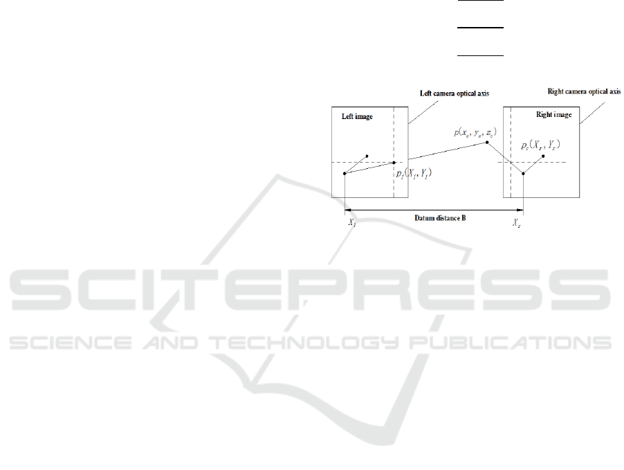
(ZHANG Qixun, 2014).
As shown in Figure 1, the optical axis of the left
camera and the right one is a pair of parallel axes,
and the distance between the two cameras is
recorded as baseline B. When the left and right
camera simultaneously observe the same point P, the
coordinates of point P are recorded as p
l
(X
l
,Y
l
) and
p
r
(X
r
,Y
r
) respectively. Assuming that the image
information collected by two cameras is on the same
plane and the focal length is f, the mathematical
relationship can be derived as follows:
(1)
The space coordinates of point P can be derived
by using the formula (2) in the camera coordinate
system:
(2)
Figure 1: 3D stereoscopic imaging principle
3.3 Error Analysis
As a measuring equipment, the precision of four-
wheel aligner is the main criterion to determine its
application value. Based on the above analysis, it is
concluded that the camber angle and the toe-in angle
can be measured directly, so there is no theoretical
error and can achieve extremely high precision.
However, when measuring the kingpin angle, the
approximate linear formula can only be deduced by
establishing the space geometry model, and then the
wheel alignment parameters are calculated by
combining the data obtained by the inclination
sensor and the approximate linear formula.
However, the linear formula does not reflect the true
motion state. Thus, different mathematical models
will cause different errors, as well as the actual
detection errors, which constitute the main error of
the four-wheel aligner. The following deduction is
taken as an example of measuring the kingpin
inclination angle by using a four-wheel aligner with
inclination sensor.
Taking the left front wheel as an example, when
the wheel turns left or right to , the
relationship between the kingpin inclination angle
and measurement angle is deduced as follows:
(3)
Technical Development and Analysis of Four-wheel Aligner for Automobiles
557
The formula (3) indicates that the kingpin
inclination angle is times that of the
actual measurement angle
. Using the
relationship of times to set the four-wheel
aligner can directly measure the kingpin inclination
angle , then formula (3) is a linear model of the
four-wheel aligner with inclination sensor.
However, in the derivation of formula (3), the
measurement result of the four-wheel aligner is
biased with the real value due to the approximate
treatment of the small angle. When considering the
effect of the small angle on the result, the following
relationships can be obtained:
(4)
(5)
(6)
Among them, the b
1
,c
1
,b
2
,c
2
are all related to the
caster angle , the kingpin inclination angle and
the horizontal rotation angle .
From the above, it can be seen that the
measurement angle
is the function of the
caster angle , the kingpin inclination angle and
the horizontal rotation angle , and the kingpin
inclination angle is obtained by
measurement angle
, so the kingpin inclination
angle is influenced by the caster angle . However,
the linear model of the four-wheel aligner with
inclination sensor does not consider the caster angle
, so it has theoretical error to measure it (XU Guan,
2006).
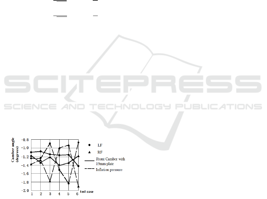
Figure 2: two factors impact on Front Tire Camber
4 CONCLUSION AND
DEVELOPMENT TREND
We found that the static wheel alignment
measurement is not strongly affected by many of the
variables tested. These included, equipment
accuracy, suspension preload, and operator.
However, the largest effects on wheel alignment
accuracy that can be expected to arise in a plant or
wheel alignment shop are caused by levelness of the
platform and errors in tire pressure (Patel H, 2016)
(see Figure 2). Therefore, the four-wheel aligner
based on static measurement will pay more attention
to the levelness of the platform and tire pressure in
the future, while increasing the degree of automation
to reduce human participation.
In addition, the four-wheel aligner based on the
computer vision measurement technology brings
great reform to the traditional wheel alignment (LV
Xiaojun, 2011), and the detection equipment with
3D image as the mainstream is gradually replacing
the traditional four-wheel aligner. However, while
pursuing accurate wheel alignment parameters, other
problems also arise. Among them, the diagnosis of
large amount of information and uncertain factors
are the disadvantages of electronic computing. For
the existing four-wheel aligner, the calibration is still
subject to artificial adjustment, so it is very
important to operate conveniently while ensuring its
stability and reliability. In the future market, people
no longer only focus on the accuracy of measuring
instruments but require as few steps as possible,
which aims to reduce the incidental error caused by
human operation and shorten the training time of
technicians. In this era of rapid development of
automobiles, the automobile industry is gradually
forming more complete information resources. For
the four-wheel aligner, in order to solve the above
problems from the root, I believe that the global
empirical database will be formed in the near future,
at that time automakers and four-wheel aligner
manufacturers will work together to develop the best
data and upload it. At the same time, in order to
achieve the most authentic positioning effect, the
four-wheel aligner can be loaded in the car body.
When the vehicle is running, the four-wheel aligner
will monitor the wheel state in real time and use the
network to compare directly with the standard in the
database. If the result is outside the standard range,
the four-wheel aligner automatically adjusts the
wheel to the proper position when the vehicle stops,
which realizes the integration of detection and
adjustment.
In addition, the new four-wheel aligner can be
added to the active safety system. Such a proposed
active safety system is a lane departure warning
where an driver support system acts as a copilot to
monitor lane –keeping performances, and warn the
driver when a lane departure is predicted (SG Barhe,
2016). Therefore, the invention of a humanized and
ICECTT 2018 - 3rd International Conference on Electromechanical Control Technology and Transportation
558

intelligent four-wheel aligner based on computer
vision measurement technology and ergonomics will
become the common goal of future.
ACKNOWLEDGEMENTS
This work is supported by grant 201611058009 of
National Training Program of Innovation and
Entrepreneurship for Undergraduates.
REFERENCES
XU Guan. Research on vision system of vehicle wheel
alignment parameters and calibrating method[D]. Jilin
:Jilin University, 2009.
LV Xiaojun. Verification device of 3D four-wheel aligner
and Its optimization design[D]. Jilin:Jilin University,
2011.
DAI Renqiang, WANG Mengjun. Research on automobile
Four-wheel aligner and calibration device[J].
Public Communication of Science
& Technology, 2013, 5(8):101-105.
ZHANG Mei, HUANG Rujun. Influence of four-wheel
aligner on vehicle driving performance[J]. Journal of
Chongqing University of Science and Technology (
Natural Sciences Edition ), 2008, 10(3):56-60.
ZHAO Qiancheng, HUANG Dongzhao,YANG
Tianlong,et al. Research on the key techniques of 3D
computer vision four-wheel aligner[J]. Chinese
Journal of Scientific Instrument, 2013, 34(10):2184-
2190.
WEN Dong. 2009 Positioning New Perspective[J]. For
Repair & Maintenance, 2009, (5):28-29.
XU Guan,SU Jian,PAN Hongda,et al. Research on
verification technology of four-wheel alignment
instrument for automobiles[J]. Measurement
Technique, 2007,(8):44-47.
ZHANG Qixun, SHAO Chenghui,ZHANG Zhongyuan, et
al. Research on the key detection technology of 3D
four-wheel alignment calibration device[J].Chinese
Journal of Scientific Instrument, 2014, 35(9):1979-
1989.
XU Guan. Study on the Calibrating Method and
Apparatus of Four-wheel Aligners[D]. Jilin : Jilin
University,2006.
Patel H, Casino M, Noakes D, et al. Suspension Variables
Influencing Static Vehicle Wheel Alignment
Measurements[J]. 2016, 9(2):551-559.
SG Barhe, BG Gawalwad. Measurement of Wheel
Alignment using IR Sensor[J]. 2016, 4(2): 158-161.
Technical Development and Analysis of Four-wheel Aligner for Automobiles
559
