
Research and Application of Visual Odometer Based on RGB-D
Camera
Guoxiang Li and Xiaotie Ma
School of Information Engineering, Beijing Institute of Fashion Technology, Beijing, 100029, China
15510262290@163.com, gxymwj@bift.edu.cn
Keywords: Depth camera, ORB, odometer, nonlinear optimization.
Abstract: Possessing accurate odometer is the basis of simultaneous localization and mapping accuracy of mobile robot.
In view of the huge error and high cost of mobile robot odometer, the visual odometer based on depth camera
(RGB-D) is studied. In this paper, the key points are extracted through ORB features which are matched by
using fast nearest-neighbor algorithm. And the 3D-3D method is used to obtain the change of camera pose
through nonlinear optimization in order to achieve a more accurate visual odometer, which will establish a
stable foundation for precise positioning and mapping of mobile robots.
1 PREFACE
Mobile robot technology is currently one of the most
active areas of research. Its wide range of applications
can greatly facilitate people's production and life.
Autonomous navigation technology (Liu, 2013) is the
basis of being widely used for mobile robots. The
traditional technology uses GPS to position and
navigate, which has more accurate only when used
outdoors. When the robot moves indoors, the GPS
hardly obtain the positioning information and can not
accurately position the robot. However, the
autonomous navigation technology of the mobile
robot requires the robot to accurately locate the robot,
which requires the robot to carry the high-accuracy
odometer. In the past, encoder, camera, laser radar,
etc, are used to satisfy the needs of the odometer.
Cameras are cheap and can get rich information. But
because RGB cameras can only capture RGB images
and can’t capture deep images, which produce huge
odometer errors sometimes. Encoder is cheaper, and
the algorithm is relatively simple. But only using the
encoder can produce greater error because of the
wheel slippery and other factors. The greater error
produces the greater uncertainty for positioning and
mapping later. Although the lidar can accurately
measure the mileage, but the price of lidar is too high
to be applied widely.
In recent years, sensors that produce RGB images
and deep images can solve these problems. In this
paper, the RGB-D camera is Astra. The RGB-D
camera can generate RGB image and depth data at the
same time. And 3D point cloud data can be obtained
after the camera calibrated. RGB-D camera is cheap
and can be used to get color images and depth data.
Therefore, the RGB-D camera can achieve more
accurate mileage and provide accurate mileage
information for positioning and mapping of mobile
robot.
2 EXTRACTION AND
MATCHING OF FEATURES
The visual odometer is based on the information of
adjacent images to estimate the motion of the camera,
which provides a better basis for the precise
positioning and mapping. The visual odometer that
based on feature point method has been regarded as
the mainstream method of visual odometer. It is a
mature solution because of its stable operation and
insensitive to light and dynamic objects.
In this paper, ORB feature (E. Rublee, 2011) is
used to extract feature points and help solve FAST
corner‘s omnidirectional problem. And the binary
descriptor BRIEF make the feature extraction process
be accelerated, which is very representative real-time
image characteristics in current time. The ORB
feature is composed of key points and descriptions.
And the key point is an improved FAST corner. The
descriptor is called BRIEF. Therefore, the extraction
of ORB features has two steps:
546
Li, G. and Ma, X.
Research and Application of Visual Odometer Based on RGB-D Camera.
In 3rd International Conference on Electromechanical Control Technology and Transportation (ICECTT 2018), pages 546-549
ISBN: 978-989-758-312-4
Copyright © 2018 by SCITEPRESS – Science and Technology Publications, Lda. All rights reserved

2.1 Extraction of FAST corner points
Finding the "corner point" in the image and
calculating the main direction of the feature points.
FAST corner points mainly detect the obvious
changes of partial pixel gray. If a pixel is significantly
different from the pixel in the neighborhood, it is
likely to be the corner point. FAST corner detection
method is convenient compared with other corner
detection methods. The process is as follows:
First, selecting the pixel p in the image and
assume the brightness
p
I
;
Setting a threshold T;
Taking the pixel p as the center, selecting a
circle with radius 3 and taking 16 pixels on
the circle;
If the brightness of the continuous N pixels
on the circle is greater than
TI
p
or less
than
TI
p
, then the pixel point can be
considered as a feature point;
Perform the above four steps for each pixel in
the image to extract the feature points;
In general, taking N as 12 (that is FAST-12). In
the FAST-12 algorithm, a predictive test can be added
to quickly exclude pixels that are not angular points
to further improve efficiency. Direct detection is used
on each pixel's neighborhood round 1, 5, 9, and 13
pixel brightness. when there are three quarters of
pixels greater than
TI
p
or less than
TI
p
at the same time, the pixel is likely to be a corner. As
a result of the original FAST corner often appear the
phenomenon of cluster, using the method of non-
maximal value suppression keep only corner points of
the maximum response value in a certain area. The
Harris response value is calculated for each FAST
corner point, and then the top N corner points with
larger response values are extracted as the final
congregation of corner points. Because FAST corner
points are not directional and scale, the ORB adds a
description of scale and rotation to it. Using the
method of gray matter calculates the rotation of the
characteristics by constructing the image pyramid and
using the detection corner at every level of the
pyramid to achieve the invariance of the scale. Hence,
FAST corners of rotation and scale are produced.
2.2 Extraction of the BRIEF descriptor
It is used to describe the image area around the feature
points. Because the ORB calculated the direction of
key points at the extraction stage of FAST feature
points, the "Steer BRIEF" feature of the rotation was
calculated by using the direction information to
calculate the rotation invariance of the ORB.
The ORB can still perform well when it is in
translation, rotation and scaling. The real-time
performance of FAST and BRIEF combinations is
also very good, which ensures the ORB features
applied in the visual odometer. The fast
approximation nearest neighbor algorithm in Opencv
can rapidly deal with matching points. It can be used
to accurately match the feature points in two pictures,
because the algorithm is already very mature. The
extraction of ORB feature points and the method of
fast approximation nearest neighbor calculation can
provide accurate data information for the camera
position transform, and it can meet the real-time
requirement of the odometer.
3 EXTRACT THE POSTURE
CHANGE OF THE CAMERA
RGB-D camera (J. Sturm, 2013) can obtain RGB
image and depth data, and ORB features can extract
and match the features. A number of matching points
can be captured to obtain a better set of matches after
matching the two adjacent images:
nn
ppPppP
,,,,,
11
LK
(1)
From the point obtained by the matching,
assuming the Euclidean transformation R and t can be
obtained:
tpRp
ii
(2)
In this paper, there is no camera model in 3D pose
estimation, so just consider the transformation
between 3D points. In the estimation of the position
(Kerl C, 2013), the method of the nearest point can
solve the pose estimation. ICP is used to refer to the
most recent point method. The problem of ICP can be
solved by linear algebra or nonlinear optimization.
Nonlinear optimization method can obtain the
minimum error for camera position change, but the
method of linear algebra can't guarantee the minimum
error. This paper the method of nonlinear
optimization solved ICP problem, through nonlinear
optimization method to get precise camera position
change.
The definition of error is:
tpRpe
iii
(3)
Research and Application of Visual Odometer Based on RGB-D Camera
547
Therefore, the objective function required by
nonlinear optimization method is obtained:
n
i
ii
pp
1
2
2
exp
2
1
min
(4)
In this paper, Gauss Newton (Kummerle R, 2011)
algorithm is used to solve nonlinear optimization.
Gaussian Newton algorithm is one of the simple
algorithms in optimization algorithm. The function
can be first-order Taylor expansion:
XJxexxe
(5)
J
is the derivative, and it's the Jacobian matrix.
The incremental equation that will be introduced into
Gauss Newton method:
gx
H
(6)
H is
JJ
T
, g is
eJ
T
. The incremental
equations can be found by iteratively finding the
Jacobian matrix and the error.
In nonlinear optimization, the minimum value can
be obtained by continuous iteration. In this paper, the
position of camera is optimized by using g2o
optimized library, and the accurate position
estimation can be obtained.
4 EXPERIMENTS
The experiment environment is ubuntu16.04 with
opencv3 image processing library and g2o
optimization library. The experiment uses Astra’s
depth camera to obtain RGB images and depth
images. The resolution of the RGB image is 640 * 480
and the depth range is 0.6 to 8 meters. First, the two
images captured by the camera are extracted and
matched. The detect function in Opencv can extract
corner points, and the compute function calculates the
BRIEF descriptor based on the corner points to
extract features. Better matching points can be
obtained, and the pose change of the camera can be
estimated through the matching feature points in the
two pictures.
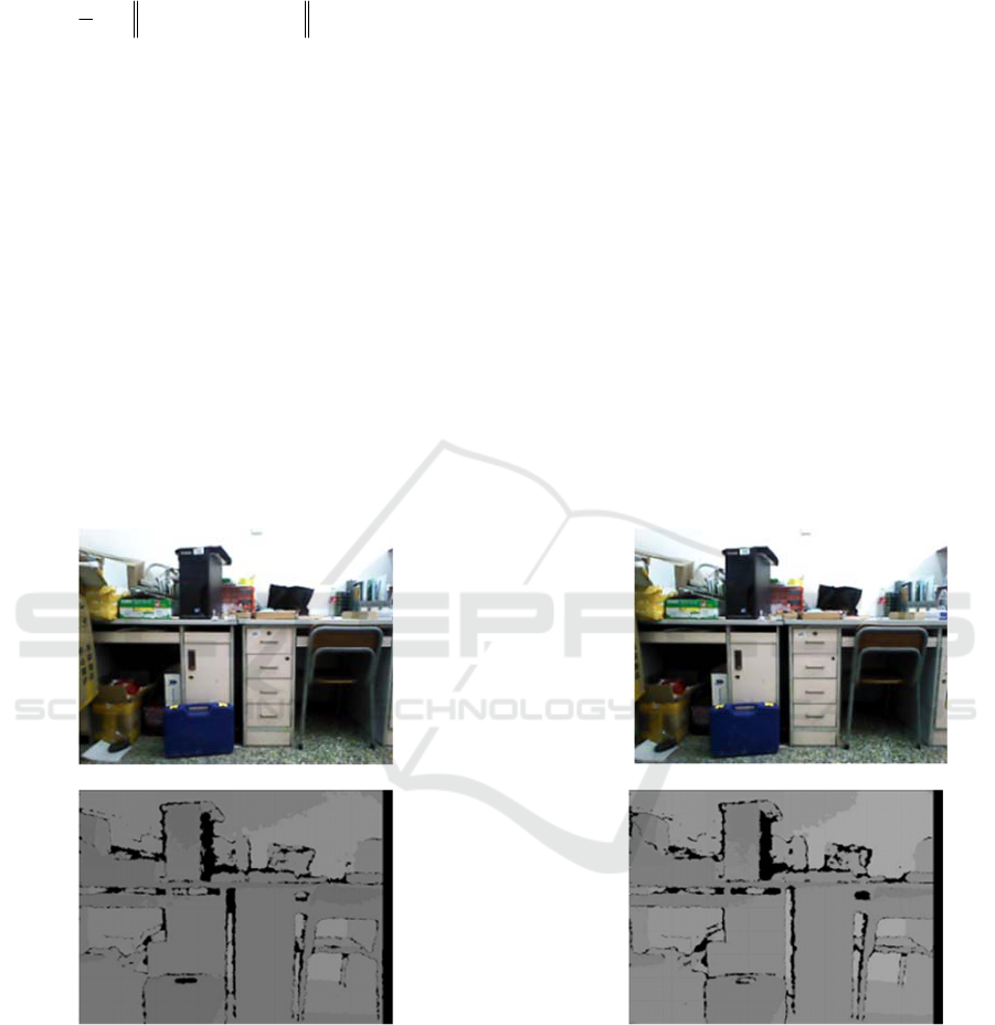
The RGB image and depth image obtained
through the RGB-D camera is shown in the figure
below:
(a) (b)
(c) (d)
Figure 1
In figure 1, (a), (b) are RGB images, and (c)(d) are
the depth images. The RGB image is extracted and
matched by the ORB feature to obtain better matching
points, and the obtained feature points are optimized
in the g2o optimization library to obtain the
transformation matrix T of camera position change. It
is shown in the following figure:
ICECTT 2018 - 3rd International Conference on Electromechanical Control Technology and Transportation
548
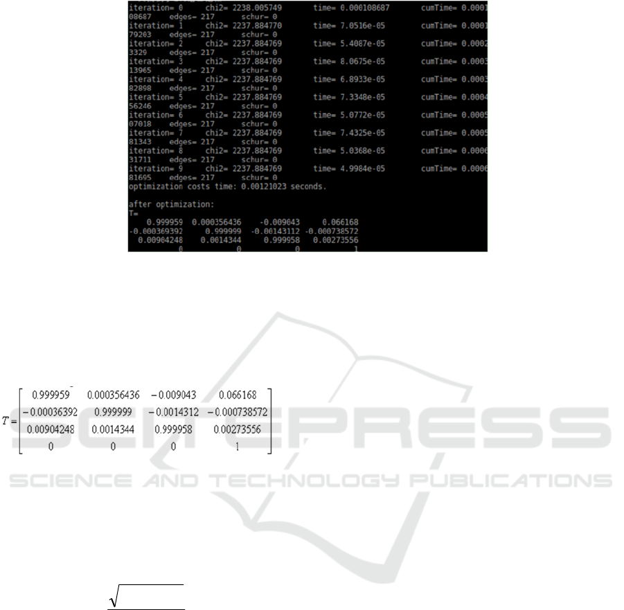
Figure 2
In figure 2, the optimization of ICP has been
stable until the fourth iteration. This shows that the
algorithm has converged after the third iteration.
The resulting transformation matrix is:
According to the transformation matrix, the
camera shifted 0.066168 meters in the x direction,
and shifted -0.000738572 meters in the y direction,
and shifted 0.00273556 meters in the z direction.
The camera shifted very small in y and z, and they
are negligible. Take the
33
x
T
, which is the rotation
matrix R. Convert R to quaternion:
2
1
0
Rtr
q
(7)
R into the equation (7) available
1
0
q
. The
experimental result of this paper is that the camera
translates 0.066168 meters in the x direction
without rotation.
5 CONCLUSIONS
In this paper, RGB-D camera is used to obtain
RGB images and depth images. The visual
odometer can obtain accurate camera’s position
by using algorithm of ORB feature extraction and
nonlinear optimization. The data provide a
foundation to accurately position and map for
mobile robots.
REFERENCES
Liu T,Zhang X, Wei Z, et al. A robust fusion method for
RGB-D SLAM[C]. Chinese Automation Congress.
2013:474-481.
E. Rublee, V. Rabaud, K. Konolige. Bradski, ORB: An
efficient alternative to SIFT or SURF, in Proc. IEEE
Int. Conf. Comput. Vis., 2011, vol. 13, pp. 2564–2571.
Robust Odometry Estimation for RGB-D Cameras (C.
Kerl, J. Sturm, D. Cremers), In Proc. Of the IEEE Int.
Conf. on Robotics and Automation (ICRA), 2013.
Kerl C, Sturm J, Cremers D. Robust odometry estimation
for RGB-D cam eras[J]. 2013:3748-3754.
Kummerle R, Grisetti G, Strasdat H, et al g2o: A general
framework for graph optimization[C]: Robotics and
Automation (ICRA), 2011 IEEE International
Conference on, Shanghai, 2011.
Research and Application of Visual Odometer Based on RGB-D Camera
549
