
Control and Implementation Technology for Horizontal Swivel
Daoping Xie, Dingxu Wen and Zhiwu Xue
(Cccc Wuhan Harbour Engineering Design And Research Co.,Ltd., Wuhan, Hubei, 430070, China)
Keywords: Horizontal swivel method, structural safety, control implementation,Brick wall lock.
Abstract: The horizontal swivel method used in bridge construction can avoid the effect to operation and safety, when we
need to cross the existing railway, highway, bridge and arterial traffic road. This is advantaged than other
construction methods. Through the horizontal swivel of the T-structure bridge of LiMin road, we propose the
corresponding requirements and measures for the construction process, structural safety and construction
control, at the same time, the difference between the brick wall and sand box for temporary locking is analyzed.
According to accurate swivel test data and reasonable control implementation technology, the beam is
accurately swiveled to the design position; this can be used as experience in future similar construction.
1 PROJECT OVERVIEW
The horizontal swivel method install turntable on the
bearing platform of bridge, places the pier shaft and
cantilever beam above it, so that it achieves
gravitational equilibrium. The traction system
provide the moment of couple to rotates around the
center of the turntable.
Liming Road Bridge is located beyond the north
second ring road of Chengdu. The main bridge
crosses the Baoji-Chengdu Railway in s straight line.
The swivel structure incorporates spherical hinges
turning system of slide-way support and central
spherical hinges. T-structure cantilevers are 41+41m.
Angle of swivel is 90 degrees. Total weight of swivel
system is about 68000kN.
Existing railway
Closure segments
Swivel structure
Fig.1: Swivel Bridge overall arrangement
2 KEY POINTS OF
CONSTRUCTION
The swivel construction implementation control
mainly includes: turntable construction phase and
swivel system construction phase.
Before and after the swivel construction, the
posture of the whole swivel structure is ensured to be
in a controllable range, through various control
measures.
2.1 Turntable construction
Turntable construction primarily involves spherical
hinges and slide-way. They are the key factor to
successful swivel implementation, and also directly
impact the precision. So, the installation accuracy
should be controlled strictly.
(1) The deviation between the central position of
spherical hinges and theoretical center is not greater
than ±1mm.
(2) The error of flatness and concentricity of
spherical hinges is less than ±1mm.
(3) The error of slide-way surface is less than ±
1mm.
In order to ensure the installation system of
swivel system, the spherical hinges incorporates one
central measure point and eight horizontal measure
points. The slide-way involves 60 horizontal
measure points with 30 points on inside and outside
surfaces. Measuring points are distributed in Fig.2.
Xie, D., Wen, D. and Xue, Z.
Control and Implementation Technology for Horizontal Swivel.
In 3rd International Conference on Electromechanical Control Technology and Transportation (ICECTT 2018), pages 405-408
ISBN: 978-989-758-312-4
Copyright © 2018 by SCITEPRESS – Science and Technology Publications, Lda. All rights reserved
405
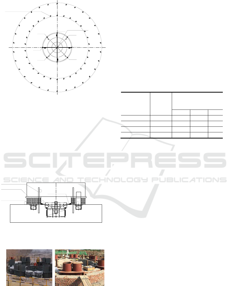
Slide-way
Spherical hinge
Center point
MP 1
MP 2
MP 3
MP 4MP5
MP 6
MP 7
MP 8
Slide measuring point
Fig.2: Measuring points layout of Spherical hinges and
slide-way
In order to avoid swivel and overturn of
turntables before the swivel construction, temporary
locking is installed between the turntables. By
conventional methods, the sand box supports and
screw-thread steel anchors are used to lock at same
time, and the wedge blocks are inserted between
support feet and slide ways to avoid swivel. This
project is supported by the brick wall, and anchored
by six steel rails between the upper and lower
turntables, which can lock together, as shown in Fig.
3.
brick wall locking
Steel rails anchors
1
4
2
3
Mortar bottom
Bottom formwork
Fig.3: The diagram of Brick wall lock
Construction situation of traditional method and
present method is shown in Fig. 4.
Fig.4: Construction situation of traditional method and
present method
2.2 Swivel construction
When the swivel system construction is completed,
the swivel construction can be implemented. Swivel
construction includes test swivel and formal swivel.
Test the swivel before the formal swivel
construction.
Test swivel provides data references to formal
swivel, including the following data: starting force
and time duration for different points, average
distance of beam-end swivel displacement distances
at 3s, 5s and 10s. Relevant data of test swivel
measurement are shown in Table 1.
Table.1: Rotor test results summary of the data
Measurements
number
Traction
force(kN)
When test swivel,the
beam-end moving distance
(
mm
)
3s 5s 10s
1 328 22 29 49
2 315 20 28 48
3 306 19 28 51
Avera
g
e value 316 20 28 49
When test swivel is started for the first time,
greater traction force is 520kN. The subsequent
traction force is relatively uniform stabilize at 316kN.
According to the equation of traction force, the
Friction coefficient of the rotating system is
calculated as 0.034, which less than theoretical
value.
Key points of test and formal swivel:
(1)Based on safety regulations and requirements,
swivel is completed within the limited time.
(2) Observe the gap between support feet and
slide ways; promptly adjust positions of sliding
plates.
(3) Pay extra attention to status and position of
swivel system and lower the swivel speed before
reach the right position to prevent excessive swivel.
The speed and time control of formal swivel:
linear velocity of beam end is 1.2m/min. Angular
velocity is 0.0293rad/min.
2.3 Turntable status and control
In the process of formal swivel, the ball hinge plays
a major role in support the swivel system. At the
same time, due to the influence of moment force and
other factors, the support feet fall on the Slide-way
usually. These combined to support the swivel
system by three points, so as to ensure the stability
of the whole structure. As shown in Fig. 5.
ICECTT 2018 - 3rd International Conference on Electromechanical Control Technology and Transportation
406
Spherical hinges
Support feet
Slide-way
Lower turntable
Upper turntable
R
main
R
help
R
help
Fig.5: The weighing jacks layout
The following measures must be taken,
according to the structural characteristics and
operating requirements of the turntable.
(1) The Slide-way surface should be cleaned to
avoid impurities on the Slide-way to hinder the
normal swivel,before formal swivel construction.
(2) Daub lubricating oil on the Slide-way to
reduce the friction coefficient, and ensure the
clearance distance between the support feet and the
Slide-way no more than 5mm, by filling the PTFE
skateboard.
(3) Construct sealing concrete between the upper
and lower turntable as soon as possible, when formal
swivel is completed.
3 CONTROLS OF SAFETY AND
CONSTRUCTION
3.1 Removal of temporary locking
Temporary locking is removed before swivel
construction. The removal process should involve
safety measures to prevent sudden changes of the
stress states. Main measures are stated as following:
(1) Install the steel bracket to support the
turntable. This as a safety support before and after
the temporary locking is removed.
(2) Look at Fig.3; we need symmetrically
demolition temporary locking by the order form one
to four. Brick bottom dies and brace wedges are
removed, anchor tracks are cut off, and mortar
bottom dies are removed lastly.
Sand box locking and brick wall locking are
compared in the following aspects as Table 2.
Table.2: Comparison of temporary locking methods
No Items
Locking mode
Sandbox method Brick wall method
1 Traits
Sandbox bears the
pressure, and
screw-thread steel
bear’s tension.
Brick wall bears
the pressure, and
the track bears
tension
2 Stress
Small
pressure-bearing
surface.
Large
pressure-bearing
surface.
3
Remo
ve
Sandbox is easy
to remove by
unloading sand.
Brick wall bears
pressure. Remove
difficultly.
Both structures meet requirements of temporary
locking. In construction, brick wall structures have
large pressure-bearing surfaces and small stress. But
temporary lock and template are difficult to be
removed and cleaned.
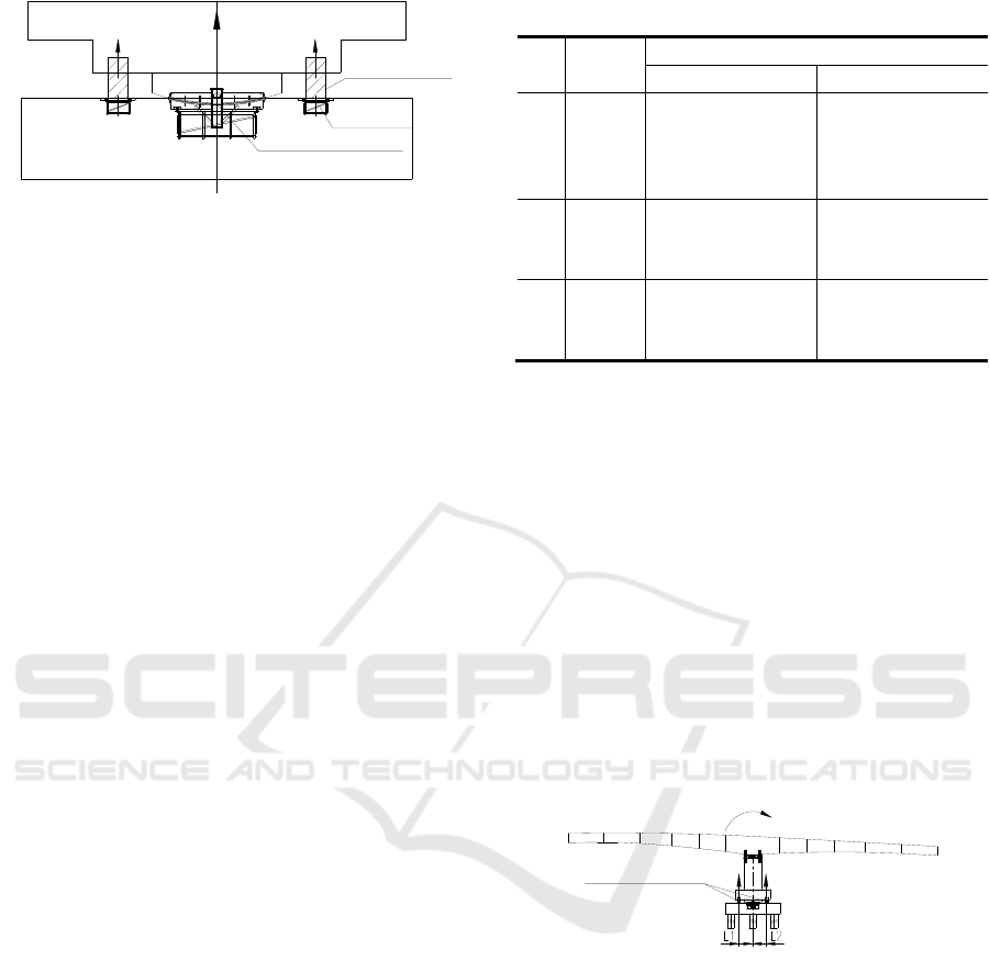
3.2 Weight and balance weight.
It is very important to carry out the weighing
experiment before swivel, which is related to the
balance of the whole swivel system.
The weighing jacks are used for weight
measuring unbalanced moment and frictional
resistance, which installation between the upper
turntable and the lower turntable. The weighing
jacks layout in Fig.6.
Weighing jacks F2F1
Mg
Fig.6: The weighing jacks layout
The principle is: equilibrium between external
lift force, unbalance moment
G
M
and friction
moment
f
M
. This involves two cases: friction
moment is less or larger than unbalance moment.
The actual measurement is that friction moment
is greater than unbalance moment. Left lifting force
1
F
is 2500kN. Right lifting force
2
F
is 4400kN.
The lift arm is
12
LL
=3.3m.
When the
1
F
of the left lifting:
11 fG
F
LM M
(1)
When the
2
F
of the right lifting:
Control and Implementation Technology for Horizontal Swivel
407

22
+
Gf
F
LMM (2)
According to the results of weight, balance
weight and position are determined. 15 00kN.m of
balance moment are needed.
3.3 Swivel process control
During the swivel process, to ensure safe and smooth
operation, the following key points are controlled:
(1) Observe the gaps between support feet and
PTFE skateboard and adjust the position of PTFE
skateboards.
(2) When beam end distance to the design
location is one meter, stop the continuous swivel and
start inching operation, according to the test swivel
result.
(3) The central line and elevation of beam end is
regulated to theoretical position. Continuous jacks
are used to align the central line of beam. Vertical
jacks are used to adjust the horizontal and vertical
gradient and elevation.
4 SUMMARY
After careful preparation, calculation and strict field
control implementation, the formal swivel was
completed within 70 minutes. The precision reached
10mm. The process and key points of swivels are
concluded as following:
(1) This methods of removal temporary locking
can ensure safety of structure, for the temporary
locking use brick wall method.
(2) Test swivel results can be used in formal
swivel, to prevent inadequate or excessive swivel.
(3) Safety and accuracy of formal swivel can be
ensured, by the control implementation technology
of the whole swivel system.
REFERENCES
Zhang J,El-Diraby T E. Constructability analysis of the
bridge superstructure swivel construction method in
China[J].Journal of construction engineering and
management,2006,132(4):353-362.
Ying-jie C. Research and Application of Bridge Swivel
Construction Technique[J].China Municipal
Engineering,2006,2:10.
Jiang L,Gao R. Deformation monitoring during removal of
the supporting of T-type rigid frame bridge constructed
by swivel method[J].Procedia
Engineering,2010,4:355-360.
Qiong Hui Li;Xiang Yang Wang;Li Li Han. Analysis on
Vertical Swivel Construction of Cable-Stayed Bridge
with Steel Arch Pylon[J].Applied Mechanics and
Materials.2013.
Fang Ru Gui.Research on the Monitoring Technology of
Cantilever Construction of Continuous
Girders in Super Large Bridges[J].Applied Mechanics and
Materials,2014,3489(638):1556-1559.
ICECTT 2018 - 3rd International Conference on Electromechanical Control Technology and Transportation
408
