
Design and Implementation of GNSS Disciplined Clock Based on
Unbiased FIR Filter
Qian Liu
1,2
, Junliang Liu
1
, Jianfeng Wu
1
, Yan Xing
1
and Haili Wang
3
1
National Time Service Center, Chinese Academy of Sciences, Xi’an, China
2
University of the Chinese Academy of Sciences, Beijing, China
3
ChinaXi'an Satellite Control Center, Xi’an, China
{
liu
j
unlian
g
, wu
j
ian
f
en
g}@
ntsc.ac.cn, liu
q
ian115
@
mails.ucas.ac.cn
Keywords: phase-locked loop, Unbiased FIR Filter, GNSS, OCXO, disciplined clock.
Abstract: The disciplined clock system aiming at providing frequency signal with excellent frequency stability, which
combines the well short-term frequency stability of the oven controlled crystal oscillator(OXCO) with the
excellent long-term frequency stability of the one pulse per second (1PPS) output of the global navigation
satellite system (GNSS) receiver. Based on the phase locked loop(PLL) structure, a disciplined clock system
mainly consisting of 3 parts has been designed, the clockbias information is get from the UBX protocol
generating by the Ublox receiver, and the unbiased finite impulse response(FIR) filter having a good
performance is used as a loop filter. Some experiments are carried out, and it shows that the Allan variance
of frequency stability of disciplined clock has been improved 2 orders and reached to
11
1.97 10
@10000s
compared to the OXCO whose frequency stability is
9
1.56 10
@10000s.
1 INTRODUCTION
The use of 1PPS signal to discipline the local OCXO
on the relevant research carried out in foreign
countries Earlier. In view of the sawtooth error of
the 1PPS signal and local crystal oscillator
frequency deviation, aging and frequency offset, this
problem was originally proposed in 1982 and Allan
and Barnes proposed using Kalman filter to solve
the problem. In 1999, Yuriy S. Shmaliy found that
the Kalman estimates may become biased when the
noise is not a Gaussian noise. Yuriy S. Shmaliy
studied a variety of ways to weaken these errors. In
2002, he proposed the Unbiased sliding average
filter to reduce the noise and found that this method
is better than the third-order Kalman filter. However,
it is possible that the OXCO will drift due to other
factors such as temperature. In this case, the filter
becomes less effective. In 2003 Nigel C. Helsby
proposed the use of balanced mixers and DDS to
achieve local oscillator frequency drift calibration,
making frequency stability to achieve greater
improvement. In 2006, Yuriy S. Shmaliy proposed
an unbiased FIR filter, which is very effective for
the TIE model. For noise signals that are not
Gaussian white noises, it also has a better inhibitory
effect.
In this paper, using the unbiased FIR filter
method as a loop filter, which is based on PLL
structure, and getting the information of clockbias
by the Ublox UBX protocol. The results obtained
using the symmetricom 5125A. In what follows,
Section 2 presents the system design of the
disciplined clock including the detailed description
of each component. Section 3 describes the
experimental platform and the measurement results.
Finally, conclusions are given at Section 4.
2 DISCIPLINED CLOCK
SYSTEM DESIGN
The disciplined clock system is essentially a phase-
locked loop which consists of three parts, including
the phase detector (PD), the voltage-controlled
oscillator (VCO) and the loop filter (LP). The role
of the phase-locked loop is to output a frequency
signal synchronized with the frequency and phase
of the input reference signal. In the synchronized
state, the phase detector output phase difference
between the input signal and the output signal is 0
or a constant. Its basic structure is shown in Fig.1,
318
Liu, Q., Liu, J., Wu, J., Xing, Y. and Wang, H.
Design and Implementation of GNSS Disciplined Clock Based on Unbiased FIR Filter.
In 3rd International Conference on Electromechanical Control Technology and Transportation (ICECTT 2018), pages 318-322
ISBN: 978-989-758-312-4
Copyright © 2018 by SCITEPRESS – Science and Technology Publications, Lda. All rights reserved
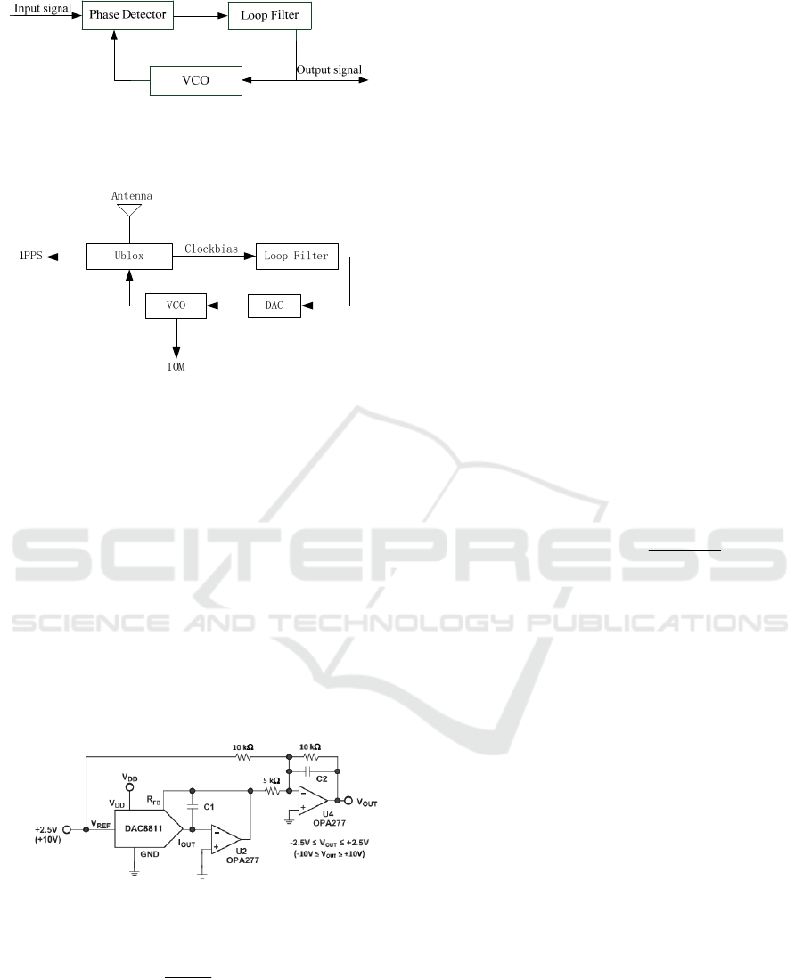
Figure 1: the structure of a phase-locked loop
The realization architecture is given in Fig.2.
Figure 2: realization architecture of the disciplined clock
The Ublox provides accurate measurement of the
external oscillator, and external interface has been
equipped with in Ublox receiver to control the
external oscillator. What’s more, the Ublox can
receive the GPS, GLONASS, BeiDou concurrently,
and it integrates a low phase noise 30.72 MHz
reference oscillator.The measurement of frequency
and phase offset usually given in the UBX protocol,
and the CPU can obtain information by the SPI/I2C.
Voltage control circuit is the most important part
of the disciplined clock system which can adjust
OCXO’s voltage value. As shown in Fig.3., the
system uses a DAC conversion chip, it is a 16-bit
precision DA, DAC8811, providing -12V ~ 12V
voltage control range.
Figure 3: voltage control circuit
The output voltage is formed by
(1)
32768
out ref
D
VV
(1)
Where D is the D/A value of the D/A converter.
Different OXCO’s voltage and frequency deviation
obey a certain function. At first, measuring the
relationship data of the voltage-controlled voltage
and frequency deviation of the OXCO. Then, fitting
their approximate function using the principle of the
least square method,. The relationship between the
output frequency signal and the D/A value is
expressed by
0.0012 39.6692
oxco
fD (2)
Where D is the D/A value of the D/A converter
and
oxco
f
is the frequency of the OXCO’s output
signal.
For the 16 bit D/A, the frequency resolution of
the voltage control circuit is 0.0012Hz. The short-
term frequency accuracy will be reach to
10
10
, the
higher the accuracy, the frequency adjustment will
be more accurate. however, the noise caused by the
circuit board should be little.
For a loop filter in a PLL, the main purpose of
which is to transfer a control signal to the VCO and
to establish the dynamic characteristics of the loop.
According to the OXCO frequency measurement
model, the measurement error can be expanded to
the Taylor series. Considering the characteristics of
the OXCO itself, only the first three terms of the
Taylor series are needed. The model expression is
22
3
112
(0)
() (0) (0)
2
xn
xn x x n
(3)
Where n can be 0, 1, 2, 3, …,
is the frequency
measurement interval,
1
(0)x
is the clock bias,
2
(0)x
is an initial frequency offset of a local clock from
the reference frequency,
3
(0)x is an initial frequency
drift rate,
is a random noise caused by the
oscillator and environment.
Let
22
1
() 0 1
00 1
nn
A
nn
(4)
And
12 3
() [ () () ()]
T
nxnxnxn
is a vector of the
clock states,
123
() [ () () ()]
T
nnnn
is the
observation vector, we have that
() ()(0)nAn
(5)
() () ()nnvn
(6)
Design and Implementation of GNSS Disciplined Clock Based on Unbiased FIR Filter
319
()vn is a mean zero noise, and ()vn
, and we
need to derive
123
ˆ
ˆˆˆ
() [ () () ()]
T
nnnn
the
unbiased FIR estimator of the clock states, using
the N points of the nearest past,
1
0
ˆ
() ()( )
N
i
nHini
(7)
2
1
0
() 0 0
() 0 () 0
00 ()
hi
Hi hi
hi
(8)
and the coefficients have the following properties:
01
()
0
()
l
l
hiN
hi
otherwise
i
(9)
The block diagram of the unbiased FIR filter is
illustrated in the Fig.4,the measurement
1
()n
is
filtered by the FIR
2
()hi and the output
1
ˆ
()
x
n
represents the unbiased estimate of clockbias, the
output
2
ˆ
()
x
n
represents the unbiased estimate of
the derivative of
1
ˆ
()
x
n
,and so forth.
2
()hi
1
()n
1
ˆ
()
x
n
2
ˆ
()
x
n
3
ˆ
()
x
n
11
ˆ
ˆ
() ( 1)xn xn
1
()hi
22
ˆˆ
() ( 1)xn xn
0
()hi
2
()n
3
()n
Figure 4: the block diagram of unbiased FIR filter
2
1
0
1
12
0
1
2111
0
1
3022
0
0
ˆ
() ()( )
1
ˆˆ
ˆ
() ()[ ( ) ( 1)]
1
ˆˆ
ˆ
() ()[ ( ) ( 1)]
N
i
N
j
N
k
xn hi n i
xn hjxn j xn j
xn hkxn k xn k
N
(10)
And the first estimate
1
ˆ
()
x
n
appears at
2
1N
,
the first estimate
2
ˆ
()
x
n
appears at
12
1NN
, and
the first estimate
3
ˆ
()
x
n
appears at
012
1NNN
,
where the FIRs
0
()hi
,
1
()hi
and
2
()hi
are given
respectively
0
1
()hi
N
(11)
1
2(2 1) 6
()
(1)
N
i
hi
NN
(12)
22
2
3(3 3 2) 18(2 1) 30
()
(1)(2)
NN Nii
hi
NN N
(13)
3 EXPERIMENTAL PLATFORM
AND EXPERIMENTAL
RESULTS
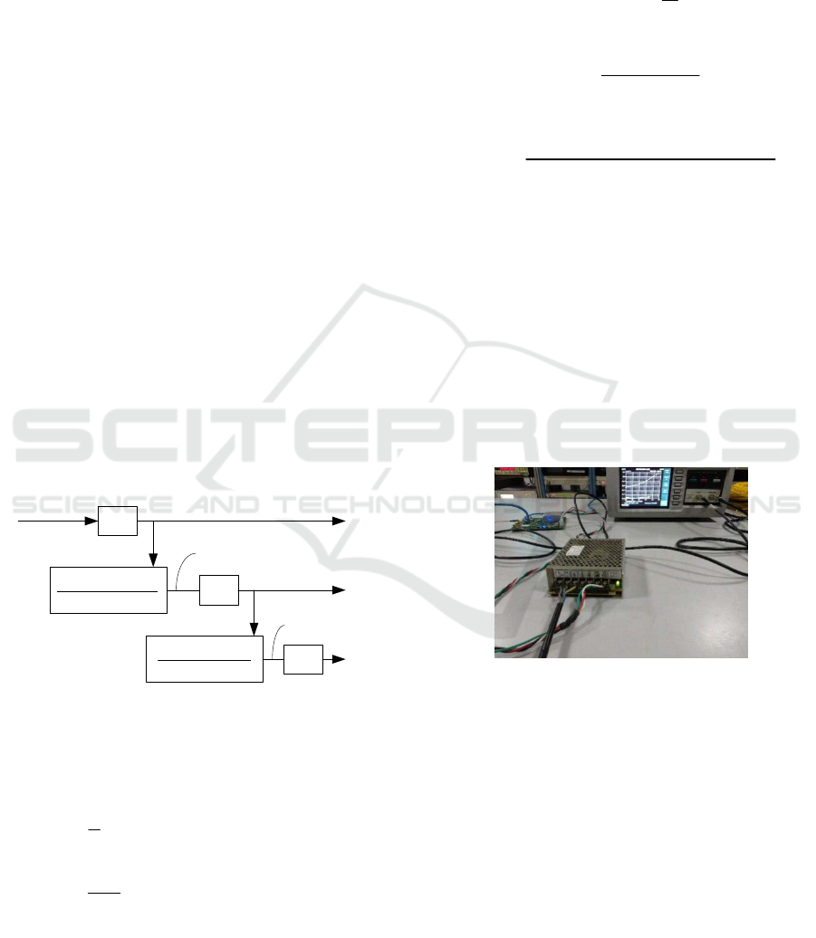
3.1 Experimental Platform
To evaluate the performance of the output frequency
of the circuit board, the measurement set is
organized as shown in Fig.5,
Figure 5:the measurement set
The 10MHz frequency signal of the disciplined
clock goes to the first input of the Phase noise
analyser symmetricom 5125A which has great phase
noise performance, -140dBc/Hz at a 1Hz offset
(10MHz fundamental), makes it the perfect solution
to characterize the lowest noise frequency reference
available, and the reference signal is the 10MHz
signal frequency in NTSC (National Time Service
Center in China) going to the second input of the
symmetricom 5125A.
ICECTT 2018 - 3rd International Conference on Electromechanical Control Technology and Transportation
320
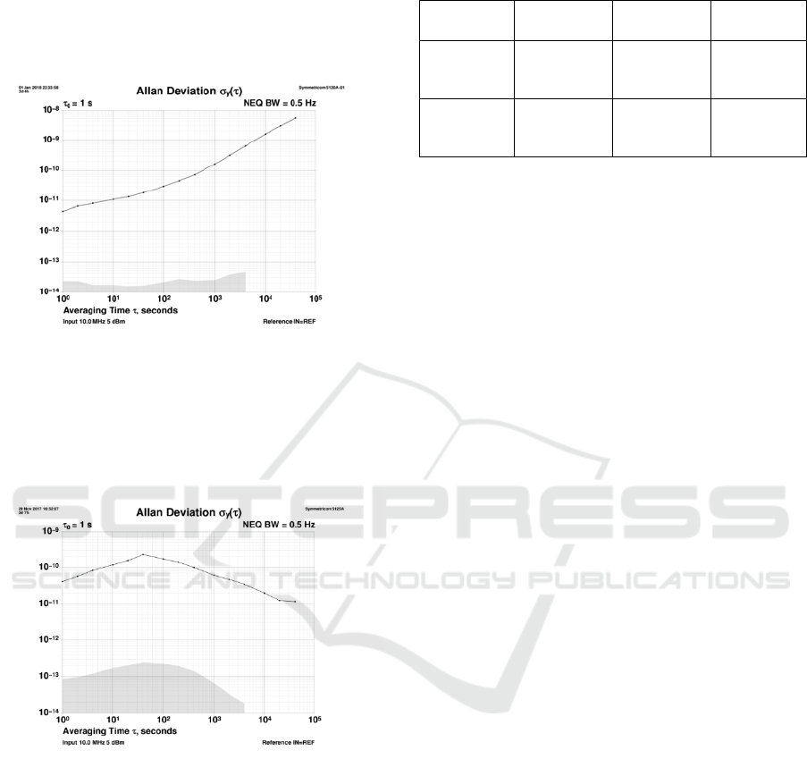
3.2 Frequency stability analysis
After 2 days’ measurement, the Allan deviation
results of each component are shown in Fig.6 and
Fig.7.
Figure 6: the Allan deviation of the OXCO before
disciplined
In Fig.6., The curve goes up with
due to the
frequency drift which is mainly caused by aging and
the temperature drift.
Figure 7: the Allan deviation of the OXCO after
disciplined
In Fig.7., the curve starts to go down when
40
s
owing to the GNSS signal having an
excellent long-term frequency stability.
Table 1: the Allan deviation of the OXCO before
disciplined and after disciplined.
1
s
10
s
10000
s
Before
disciplined
12
4.736 10
11
1.120 10
9
1.56 10
After
disciplined
11
4.040 10
10
1.178 10
11
1.97 10
To compare the Allan deviation of the OXCO
before disciplined and after disciplined, presented in
Table 1, and
is the sampling interval. The short-
term stability of the OXCO become worse, due to
correcting frequency frequently, which cannot be
avoided. However, the Allan variance of long-term
frequency stability of OXCO has been improved 2
orders which is
9
1.56 10
@10000s before
disciplined and then become
11
1.97 10
@10000s
after disciplined.
4. CONCLUSIONS
The paper has presented a method to discipline the
local clock using the unbiased FIR filter as a loop
filter in the PLL, and getting the information of
clockbias by the UBX protocol.
The experiment
shows that it can improve the frequency stability of
crystal oscillator about 2 orders.
ACKNOWLEDGEMENTS
This work is supported by the West Light
Foundation of the Chinese Academy of Sciences
(Grant NO. XAB2015B13). The author would like
to express their gratitude to Prof. Yuriy S. Shmaliy
of the Guanajuato University of Mexico for the
discussions on the unbiased FIR filter algorithm.
REFERENCES
Landgrebe D A. Phaselock Techniques, 3rd Edition[J].
2003.
Allan D W. Statistics of atomic frequency standards[J].
IEEE Proceedings, 1966, 54(2):221-230.
Helsby N C. GPS disciplined offset-frequency quartz
oscillator[J]. 2003:435-439.
Design and Implementation of GNSS Disciplined Clock Based on Unbiased FIR Filter
321

Allan D W, Barnes J A. Optimal Time and Frequency
Transfer Using GPS Signals[C] Symposium on
Frequency Control. 1982:378-387.
Mosavi M R. Use of Accurate GPS Timing Based on
Radial Basis Probabilistic Neural Network in Electric
Systems[C]. International Conference on Electrical
and Control Engineering. IEEE Computer Society,
2010:2572-2575.
Shmaliy Y S, Marienko A V, Savchuk A V. GPS-based
optimal Kalman estimation of time error, frequency
offset, and aging[C]. Precise Time and Time Interval.
1999.
Shmaliy Y S. A simple optimally unbiased MA filter for
timekeeping.[J]. IEEE Transactions on Ultrasonics
Ferroelectrics & Frequency Control, 2002, 49(6):789-
97.
Shmaliy Y S. An unbiased FIR filter for TIE model of a
local clock in applications to GPS-based
timekeeping[J]. IEEE Transactions on Ultrasonics
Ferroelectrics & Frequency Control, 2006, 53(5):862-
70.
Shmaliy Y S, Ibarra-Manzano O, Arceo-Miquel L, et al. A
thinning algorithm for GPS-based unbiased FIR
estimation of a clock TIE model[J]. Measurement,
2008, 41(5):538-550.
Shmaliy Y S, Torres-Cisneros M, Marienko A V, et al.
GPS-based time error estimates provided by
smoothing, Wiener, and Kalman filters: a comparative
study[C] Precise Time and Time Interval. 2000.
Shmaliy Y S, Olivera-Reyna R, Ibarra-Manzano O. The
Trade-Off Between Some State Space and FIR
Algorithms in GPS-Based Optimal Control of a Local
Crystal Clock[J]. 2004.
Kou Y, Jiao Y, Xu D, et al. Low-cost precise measurement
of oscillator frequency instability based on GNSS
carrier observation ☆[J]. Advances in Space Research,
2013, 51(6):969-977.
APPENDIX
1PPS 1 pulse per second
GNSS global navigation satellite system
GPS global positioning system (U.S.)
NTSC national time service center
OCXO oven controlled crystal oscillator
FIR finite impulse response
GLONASS global navigation satellite system
ICECTT 2018 - 3rd International Conference on Electromechanical Control Technology and Transportation
322
