Design of the Wire Repair Tool for the Maintenance Robot with
Electrification Used in Substation
Gang Dong
1
, Xu Dong
2
,Qiang Chen
2
and Yan Zhang
2
1
State Grid Shandong Electric Power Company ,Jinan,China
2
Shandong Luneng Intelligence Technology Co. Ltd. Jinan,China
dxengineer@163.com
Keywords: Open-type Substation, Wire repaired, Worm and Gear, Remote Control.
Abstract: The power transmission lines in open-type substation which long-term exposure to the outdoor environment
easily occurs in the phenomenon of wire breakage in the harsh environment of wind and sun .The broken
wire in lines would appear the phenomenon of vibration breakage due to the role of external forces when
working. The further expansion of the steel core aluminium strand would lead to a decrease in the
mechanical strength of the line, and then resulting in a safety accident. The wire repair tool is the special
operation tools for the maintenance robot with charged used in substation, which is clamped by the
mechanical arm installed at the end of the robot. The wire repair tool with power transmission mode of the
worm and gear and the remote control mode to repair the damage wire of the power transmission line in the
open substation, and then reduces the danger level effectively.
1 INTRODUCTION
As the scale of substation expands gradually, the
stability of transmission lines in substations will
directly affect the reliability and stability of users.
The power transmission lines in open-type
substation which long-term exposure to the outdoor
environment, under the bad environment and the
external force, prone to broken phenomenon. If the
wire is not repaired in time, it will not only affect the
transmission efficiency for a long time, but also
affect the mechanical strength of the line. Power
transmission and transformation line carries the risk
of breaking, and then cause the safety accidents.
According to the relevant provisions, it can be seen
that the loss of damage of the wire at the same place
exceeds 5% but less than 17% of the total tensile
force and the cross-sectional area does not exceed
25% of the total cross-sectional area of the
conductive part, repairing with a repair tube. In the
current stage, the work of wire repair is mainly
repaired by artificial repair, the use of wire crimping
pliers as a crimping tool and the use of repair pipe
on the broken wire repair. The work of artificial wire
is high in strength, low in efficiency, unable to be
charged and a low degree of automation, there is a
certain security risks. There are certain safety
hazards. Researchers of State Grid Shandong
Institute of Electrical have improved the wire
hydraulic plier, and the control mode is changed
from manual to remote controlled operation, as
shown in Figure 1, which is used for 10kV
distribution network operations. The Quebec Water
Research Institute in Canada developed the wire
crimping repair tool is mainly used for overhead
lines, only applies to the line inspection robot,
cannot be used in the substation power transmission
line. At present, there is no related research about
the wire repair tool which is used in substation for
the electric maintenance robot of substation.
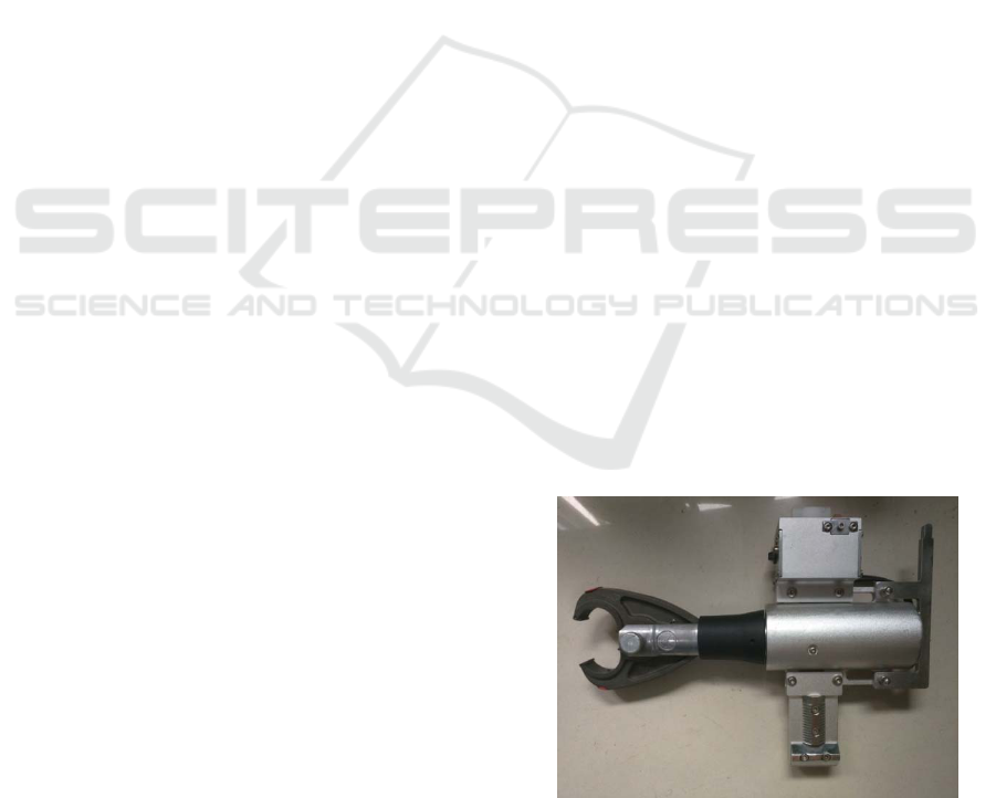
Fig.1 The wire hydraulic plier
In order to solve the problems existing in the
above research, overcome the difficulties and
Dong, G., Dong, X., Chen, Q. and Zhang, Y.
Design of the Wire Repair Tool for the Maintenance Robot with Electrification Used in Substation.
In 3rd International Conference on Electromechanical Control Technology and Transportation (ICECTT 2018), pages 131-135
ISBN: 978-989-758-312-4
Copyright © 2018 by SCITEPRESS – Science and Technology Publications, Lda. All rights reserved
131
limitations of the wire repair operation in the
substation, improve the efficiency of the wire repair
work, reduce the labor intensity of the operator,
improve the mechanical strength of the damaged
wire, and ensure the stability of the power supply of
the substation. According to the repair requirements
for damaged line of 220kV and below the voltage
level substation and the operating requirements for
the substation electromechanical operation of the
robot, a wire repair tool is designed to conduct the
repair mission which is used for the maintenance
robot with charged used in substation.
2 DESIGN OF MECHANICAL
STRUCTURE
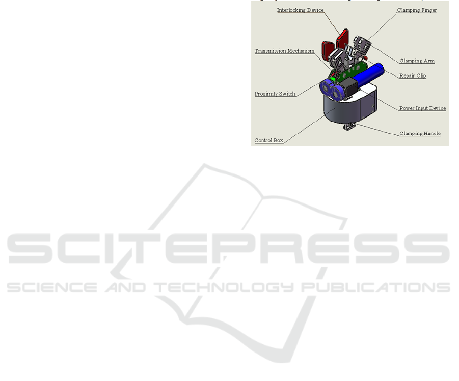
The wire repair tool is mainly composed of a repair
clip, a pair of clamping fingers and clamping arm,
the interlocking device and transmission mechanism,
the power input device, the proximity switch, control
box and clamping handle. The schematic diagram of
the wire repair tool is shown in Figure 2. The repair
clip is made with material of aluminum, which
thickness is 2mm. The material of aluminum sheet
can make the repair clip has good ductility and
mechanical strength, and it cannot spread the
aluminum strand of the broken wire. The main role
of the interlocking device is to loose stranded strand
straight and close the wire to repair clip clamping
easily, and then improve the repair efficiency. The
interlocking device uses POM which is the
insulating material to prevent the tip discharge from
occurring during contact with the wire. The
clamping fingers are the executing agencies at the
end of the tool and make the repair clip to produce
the deformation to achieve the purpose of wire
repair in the operation of the clamping arm. The
clamping fingers are also made by POM. A
miniature camera is installed in the center of the
repair clip and the position of the wire can be
observed in real time. Both ends of the clamping
arm are equipped with proximity switches to control
the travel of the clamping arm. The transmission
mechanism using worm gear drive mechanism, with
the advantages of single-stage speed ratio of worm
gear mechanism to transfer power to the clamping
fingers for operation. The power input device is the
power source of the wire repair tool, and the motor
drive mode is adopted to facilitate precise control,
and the actuator is connected to the transmission
mechanism by the decelerating mechanism of the
servo motor. The clamping handle is the manipulator
clamping part of the tool, the main body of the
clamping handle is made of hard aluminum alloy,
and the anti-wear material is used in the clamping
part with the handle in order to achieve the purpose
of the use of lightweight and ease of use. The
clamping handle can be replaced periodically.
Fig.2 The schematic diagram of the wire repair tool
3 DESIGN OF CONTROL
SYSTEM
The control system of the wire repair tool is mainly
composed of the remote control terminal, the
wireless transceiver, motor and actuator and Beckoff
control system. The block diagram of control system
for the wire repair tool is shown in Figure 3. The
remote control terminal sets the start-stop and status
button, respectively corresponding to the motor's
start-stop and state control. The communication
between remote control terminal and Beckhoff
controller through WIFI wireless, Beckhoff
controller according to the collected key information
output corresponding to the digital to EL2024 digital
output module when press the button. Digital output
module connected with the transmitter so that the
transmitter can automatically send the corresponding
signal to the receiver, and the receiver connected
with the motor. So that the motor could start and
stop, forward and reverse by the remote control
terminal. The control flow diagram is shown in
Figure 4.
ICECTT 2018 - 3rd International Conference on Electromechanical Control Technology and Transportation
132
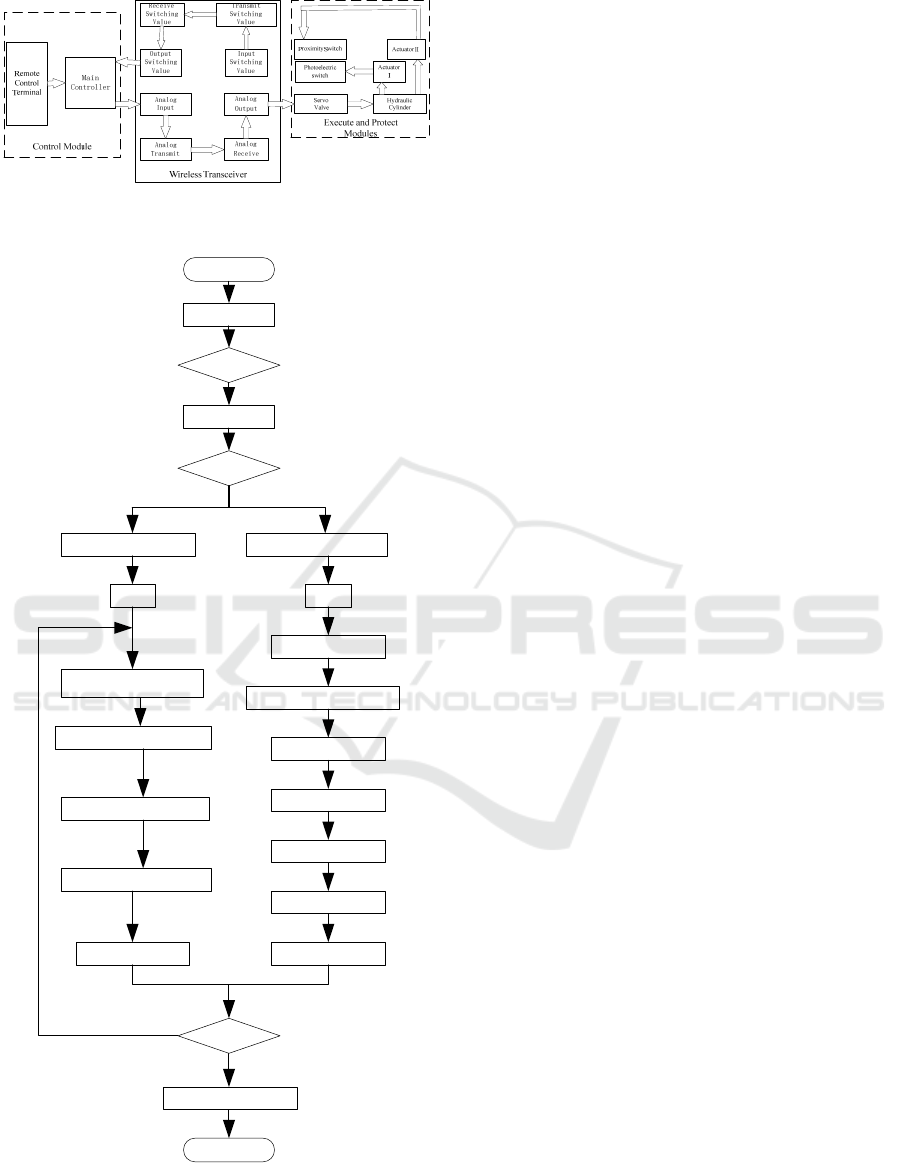
Fig.3 The block diagram of control system for the wire
repair tool
Start
Initialization
Button
Click
Read key value
K1/K2/K3…K10
D / I ?
K1/K2/K3…K8
Km Kn
Input Switching Value
Analog Input
Transmit Switching Value
Receive Switching Value
Main Controller Processing
Analog Transmit
Analog Receive
Main Controller Processing
Motor Driver
Servo Motor
Operating ToolsActuator
End
Proximity Switch
Location?
D
I
Yes
No
Fig.4 The control flow diagram
(1) Motor control
The remote control terminal output a continuous
control signal (set to "-127 ~ 127") ,and the remote
terminal communicates with Beckhoff controller
through WIFI wireless, and the receives the signal (-
127 <X <127) at the same time, and then output a 0
to 5v analog signal to EL4104 after DA conversion.
The EL4104 module is connected with the analog
wireless transmitting device and outputs the analog
signal to the transmitting device, the wireless
transmitting device and the wireless receiving device.
The wireless receiving device outputs the "0-5V"
analog signal. The wireless receiving device are
connected with the motor driver "IN1", and then the
analog signal is outputted to the "IN1" port to
complete the control of the motor.
(2) Limited control
The proximity switch would be triggered when
the clamping finger moved to the limit position, and
the proximity switch outputted a voltage signal of
5V. The proximity switch outputted signal is
connected to the wireless transmitter, and the
voltage signal is inputted to the wireless transmitter.
Since a wireless transceiver can only transmit two
signals, the limit position of one clamping finger is
detected and the other is synchronized. The wireless
transmitting device communicates with the wireless
receiving device, the wireless receiving device
synchronously outputs a voltage signal (12V) to the
wireless receiving device. The output of wireless
receive device is connected with the EL1144 module
and outputs the signal to the one of the channel. The
controller corresponds to receiving the high and low
voltage signal to control the motor's start-stop when
the proximity switch corresponds to the high and
low voltage signal.
4 THE PROCESSING OF
REPAIRING
The wire repair tool is held by the mechanical arm
and the repair process is shown in Figure 5. The wire
repair tool is clamped by the mechanical arm, and
the mechanical arm holds the wire repair tool to
enter from the undamaged side of the wire. The
mechanical arm clamps the wire repair tool slowly
moves from the damaged side to the undamaged side,
in order the clamping fingers could align the wire
through videos from the camera on the wire repair
tool. The broken wire is closed under the action of
the interlocking device. The mechanical arm stops
Design of the Wire Repair Tool for the Maintenance Robot with Electrification Used in Substation
133
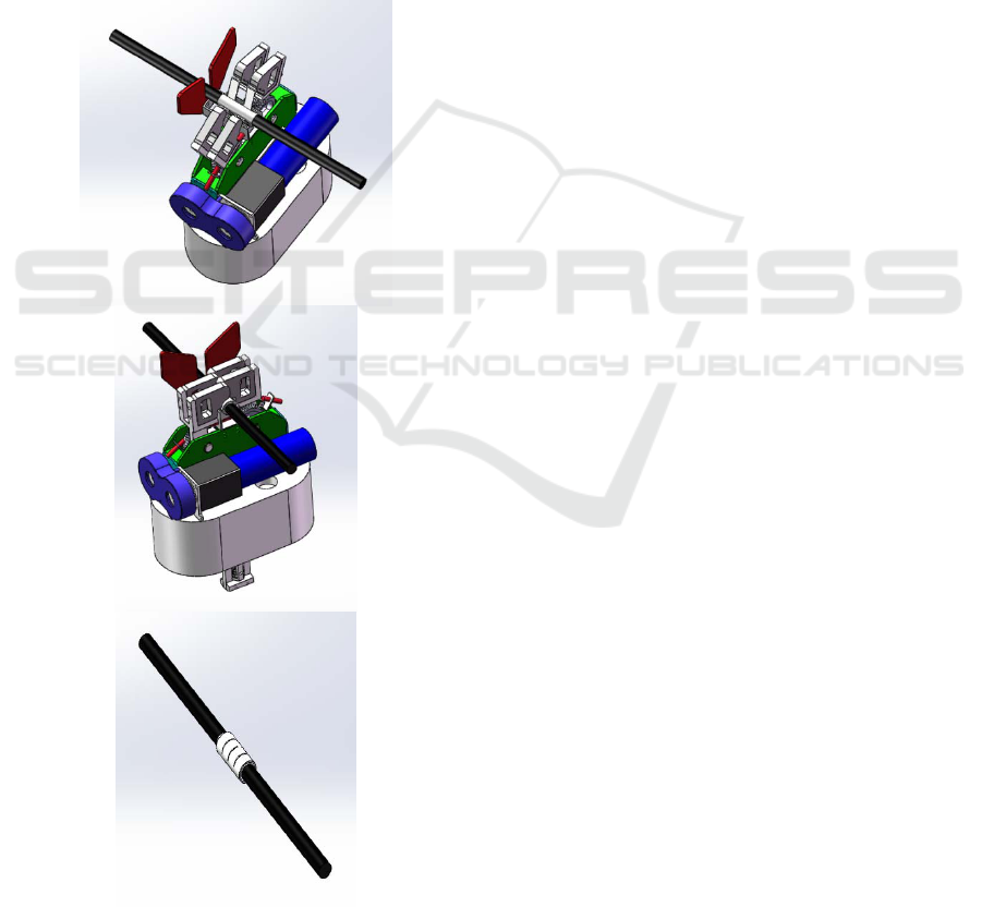
moving when the center position of the repair clip is
on the broken wire through the camera to observe,
and then the motor of the wire repair tool is
controlled by the remote controller to conduct the
repair work. The proximity switch on the wire repair
tool can detect the position of the clamping arm to
control the travel of the work. When the job is
completed, the clamping arm is rotated in the
opposite direction under the action of the motor, and
the position of the clamping arm is detected by the
proximity switch, and then the motor would stopped
after the clamping arm fully opened. The mechanical
arm holds the wire repair tool to move directly
below the wire after the repair clip is clamped in 3
times (the repairing work), and the wire repair tool is
pulled out of the wire.
Fig.5 The repair process of the wire repair tool
5 CONCLUSIONS
The work of wire repair in open type substation is of
great significance to the safe and stable operation of
substation. At this stage, the repair work in the
substation is mainly in the stage of manual with
power failure, which is in a low degree of
automation and poor economic efficiency. This
paper designs a wire repair tool for the maintenance
robot with charged used in substation, which can
repair the damaged wires in the substation without
power failure. The wire repair tool adopts the
transmission mode of the worm and gear and the
control mode of the remote control operation to
repair the power transmission line which is broken
in open type substation. The design of the wire
repair tool for the maintenance robot with charged
used in substation can improve the operation of
automation, reduce the number of blackouts, and
improve economic efficiency at the same time.
ACKNOWLEDGEMENTS
Key Technology and System Research of Robot for
Operation and Maintenance of Grid Equipment
(Technology project of China Southern Power Grid
Co., Ltd. No. 090000KK52150073)
REFERENCES
Guo Hui Ma Jing.Application of charged Wire Repair
Method of Double Circuit Tower with High-pressure
Line Getting into Strong Electric Field[J]. Journal of
Henan Science and Technology, 2015,Vol.567(7):144-
146.
ZHU Difeng, XU Yangyong, WU Kunxiang, LIU
Hongxin. New Type of Pre-Twisted Splice Bar
Application on EHV/UHV Transmission
Lines[J],2017,35(2):79-81.
CHE Li-xin YANG Ru-qing GU Yi. Design of High-
voltage Hotline Sweeping Robot Used in 220/330kV
Substation [J],ROBOT ,2005,27(2):102-107.
C.Y.G.Design of substation equipment HV hot-line
sweeping robot[J]. Robot. 2005,27(2):102-107.
F. Research of hot-line sweeping robot mobile carrier[D].
Shang Hai:Shanghai Jiao tong University, 2008.
Caccavale F, Natale C , Siciliano B, et al. Integration for
the next generation:embedding force control into
industrial robots[J]. IEEE Robotics and Automation
Magazine, 2005(9): 53-64.
Shouyin Lu, Peisun Ma and Hui Qi. Research on high
voltage electric power live line working robot.
Automation of Electric Power Systems, 2003(17).
ICECTT 2018 - 3rd International Conference on Electromechanical Control Technology and Transportation
134

A.Santamaria, R.Aracil and A.Tuduri. Teleoperated
Robots for Live Power Lines Maintenance
(ROBTET) . In: Proc of 14th International Conference
and Exhibition on Electricity Distribution,
1997,3(31):1-5.
K. Study and design of control system ultra-high voltage
hot-line sweeping robot[D]. Shang Hai: Shanghai Jiao
tong University, 2008.
Design of the Wire Repair Tool for the Maintenance Robot with Electrification Used in Substation
135
