
The Adaptive Control of Aircraft Brake Based on Asymmetric
Barrier Lyapunov Function
Jiuli Lu, Zhaohui Yuan and Bo Liang
School of Automation, Northwestern Polytechnical University, 710129, Xi’an, Shaanxi, China
lu
j
iulilove
@
163.com
Keywords: Anti-skid Brake, Asymmetric, Slip Rate Constraint, Brake Efficiency.
Abstract: Considering the complexity, non-linearity and uncertainty of aircraft antiskid control system, the author
takes such shortcomings of traditional “PD + PBM” control methods into account as low braking efficiency
and deep skidding on hybrid runways, and puts forward the constraint control algorithm of slip rate based
on asymmetric barrier Lyapunov function, which meets the purpose of adaptive full-regulation from the
concept of system integration that the slip ratio is also satisfied in the stable region where it is constrained,
so as to improve the braking efficiency. By comparing with the simulation results of the traditional “PD +
PBM” control algorithm, the author tries to show that the braking process has a good follow-up performance
and a smooth brake curve, which avoids the problem of low-speed skidding, optimizes the braking
performance and improves braking efficiency based on adaptive control algorithm of slip rate constraint.
1 INTRODUCTION
Aircraft anti-skid braking system is a complex non-
linear and uncertain system, which is affected by
many uncertainties during the landing brake process
of aircraft. It makes the structural parameters have
time-varying characteristics. Therefore, it is the key
and difficulty in the field of aircraft brakes how to
ensure the superiority of braking performance
through system design. However, the design of
system control algorithm is the key factor affecting
the braking performance of the system and the most
important factor in system design. At present, the
conventional “PID with pressure offset” control is
mostly used in practical engineering in China, that is,
the “PD + PBM” control method. Although the
system has some intelligence through the PBM
pressure bias design and the performance of the dry
runway is good, the system still has the problems of
low speed slippage and poor adaptability to the wet
runway. In the AC NO.25-7A, this method was
identified as “quasi-regulation” mode, and wet
runway braking efficiency was only identified as
50%. While such overseas professional
manufacturers are now using adaptive “full
regulation” control method as Goodrich, Safran and
Meggitt. “Full regulation” control mode was
identified as the braking efficiency of 80%, which
can meet the requirements for braking performance.
Some research has been made on adaptive
control theory of aircraft braking system at home
and abroad, mainly including feedback linearization
theory (
TANELLI M, ASTOLFI A, SAVARESI S M,
2008
), fuzzy control (R.Babuska, H.B.Verbruggen,
1996), iterative learning (MI C T, LIN H, ZHANG Y,
2005
), robust control (BASLAMISLI S C,K SE I E,
ANLAS G,2007
), synovial control (TANELLI M,
FERRARA A, 2013; CHO D-W, CHOI S, 1999; CHOI S,
CHO D-W, 2001; HEBDEN R G, EDWARDS C,
SPURGEON S K, 2004
), model- control (Shi Wei, Liu
Wensheng, Chen Jianqun, 2012
), etc. But the
confidentiality and competition is taken into account,
the relevant literature abroad only involves a brief
description of the principle for its aircraft brake
control, without the specific control algorithm in
detail. However, most domestic methods are devoted
to obtaining better control performance by adjusting
the expected value of slip ratio. Direct consideration
is rarely given to the working state of the aircraft
anti-skid braking system and its impact on the entire
aircraft system.
Based on this, the author presents a slip-rate-
adaptive control based on asymmetric barrier
Lyapunov function. The adaptive control law is
designed based on the stability of the constrained
slip ratio. On the one hand, the system works in a
stable area from the system integration level; on the
102
Lu, J., Yuan, Z. and Liang, B.
The Adaptive Control of Aircraft Brake Based on Asymmetric Barrier Lyapunov Function.
In 3rd International Conference on Electromechanical Control Technology and Transportation (ICECTT 2018), pages 102-109
ISBN: 978-989-758-312-4
Copyright © 2018 by SCITEPRESS – Science and Technology Publications, Lda. All rights reserved

other hand, it achieves the purpose of adaptive full-
regulation, thus improves braking efficiency.
2 NONLINEAR MATHEMATICAL
MODEL OF AIRCRAFT ANTI-
SKID BRAKING SYSTEM
2.1 Aircraft ground friction model and
dynamic model
The brake control needs to establish a simplified
mathematical model on the basis of reasonable
assumptions (Wang Jisen, 2001; Qiu Yanan,
2016).Taking aerodynamic characteristics into
account, the equilibrium equations in the
longitudinal, vertical and pitch directions are:
⎪
⎩
⎪
⎨
⎧
+=+−
=−−−
=−−+
hnfanNhVKTbN
NnNFG
mVnfFVKT
tXV
y
XXXV
1102
21
10
)(
0
(1)
In which,
2
5.0
XXX
SVCF
ρ
=
,
2
5.0
Xyy
SVCF
ρ
=
,
11
Nf
μ
=
Assuming that the landing gear is a rigid body,
that is, ignoring the heading speed caused by the
deformation of the landing gear. According to the
principle of brake rotor inertia, the equation of wheel
dynamics is
J
MRN
J
MM
sgSj
−
=
−
=
1
μ
ω
&
(2)
g
RV
ω
ω
=
(3)
By formula (1) ~ (3) :
hba
h
m
VKT
b
m
SVC
g
m
SVC
m
VKT
V
t
XV
Xy
Xy
XV
X
μ
ρ
μ
ρ
++
+
−
⎟
⎟
⎠
⎞
⎜
⎜
⎝
⎛
−
−
−
+
=
0
2
2
0
2
2
&
(4)
()
J
M
hba
hVKT
nJ
R
hba
bSVCmg
nJ
R
StXV
g
Xy
g
−
++
+
−
++
⎟
⎠
⎞
⎜
⎝
⎛
−
=
μ
μ
μ
ρ
μω
0
2
1
2
1
1
&
(5)
In the process of landing braking, the wheel
speed of aircraft is less than or equal to the
longitudinal speed of aircraft under the braking
torque, that is,
X
VV ≤
ω
, the rate of relative
movement is defined as slip rate, namely:
X
g
X
X
V
R
V
VV
ω
σ
ω
−=
−
= 1
(6)
The derivation of the above formula can be
obtained:
X
gX
X
g
X
g
V
RV
V
R
V
R
ωσ
ω
ωσ
&
&
&
&
−−
=
+−=
)1(
2
(7)
The formula (4) and formula (5) are put into the
above formula, and then:
S
X
g
S
X
g
X
g
XXV
X
M
JV
R
f
M
JV
R
JV
NR
m
NnFVKT
V
+=
+−
−−+
⋅
−
=
)(
1
1
2
10
σ
μ
μ
σ
σ
&
(8)
In which,
JV
NR
m
NnFVKT
V
f
X
g
XXV
X
1
2
10
1
)(
μ
μ
σ
σ
−
−−+
⋅
−
=
(9)
The definition of parameters in the above
formula is the same as (Wang Jisen, 2001; Qiu
Yanan, 2016) in the references.
2.2 Drive Mechanism and Actuator
Model
For aircraft hydraulic brake system, the drive
mechanism is composed of hydraulic servo valve,
which converts the brake current into brake pressure
via hydraulic servo valve and applies to the brake of
The Adaptive Control of Aircraft Brake Based on Asymmetric Barrier Lyapunov Function
103
the actuator to convert it into braking torque, which
interacts with the combined torque provided by the
ground, in order to decelerate the aircraft until it
stops the aircraft.
2.2.1 The mathematical model of brake
pressure servo valve
Electro-hydraulic servo valve is an important part of
the aircraft hydraulic control system, and the
pressure characteristics of electro-hydraulic servo
valve is one of the important features of the servo
valve by changing the input port of the control
current size and direction. The output pressure can
be changed in the size of the direction, according to
the nozzle baffle servo valve structure and working
principle
(Chen Zhaoguo, Li Zhigang, Huang Qi, 2005),
and the pressure equation of the dynamic equation
is:
c
e
t
q
f
L
ks
V
k
X
P
+
=
β
4
(10)
θ
rX
f
=
(11)
1
2
/1
2
2
++
⋅
=
Δ
s
s
kk
I
mf
mf
mf
tmf
ω
ξ
ω
θ
(12)
The anti-Laplace transformation of the formula
(10) is:
f
t
qe
L
t
ce
L
X
V
k
P
V
k
P
β
β
4
4
+−=
&
(13)
The formula (11) is brought intoit and then:
θ
β
β
t
qe
L
t
ce
L
V
rk
P
V
k
P
4
4
+−=
&
(14)
Similarly, the anti-Laplace transform of the
formula (12) is:
I
k
k
mfmf
mft
mfmf
mf
Δ⋅++−=
ξ
ω
ω
θ
θ
ξ
ω
θ
2
)(
2
2
&&
&
(15)
The meaning of the letters in the above formula
is described in
(Chen Zhaoguo, Li Zhigang, Huang Qi,
2005) of the references.
2.2.2 The mathematical model of brake
device
Through the overlap and installation of dynamic and
static disks, the brake device forms a larger friction
area, and absorbs the heat transformed by kinetic
energy in the process of aircraft braking, that is, the
so-called “hot reservoir”. The pressure-torque
characteristic of the braking device is one of the key
factors that influence the control performance of the
aircraft. The mathematic model is derived as
follows.
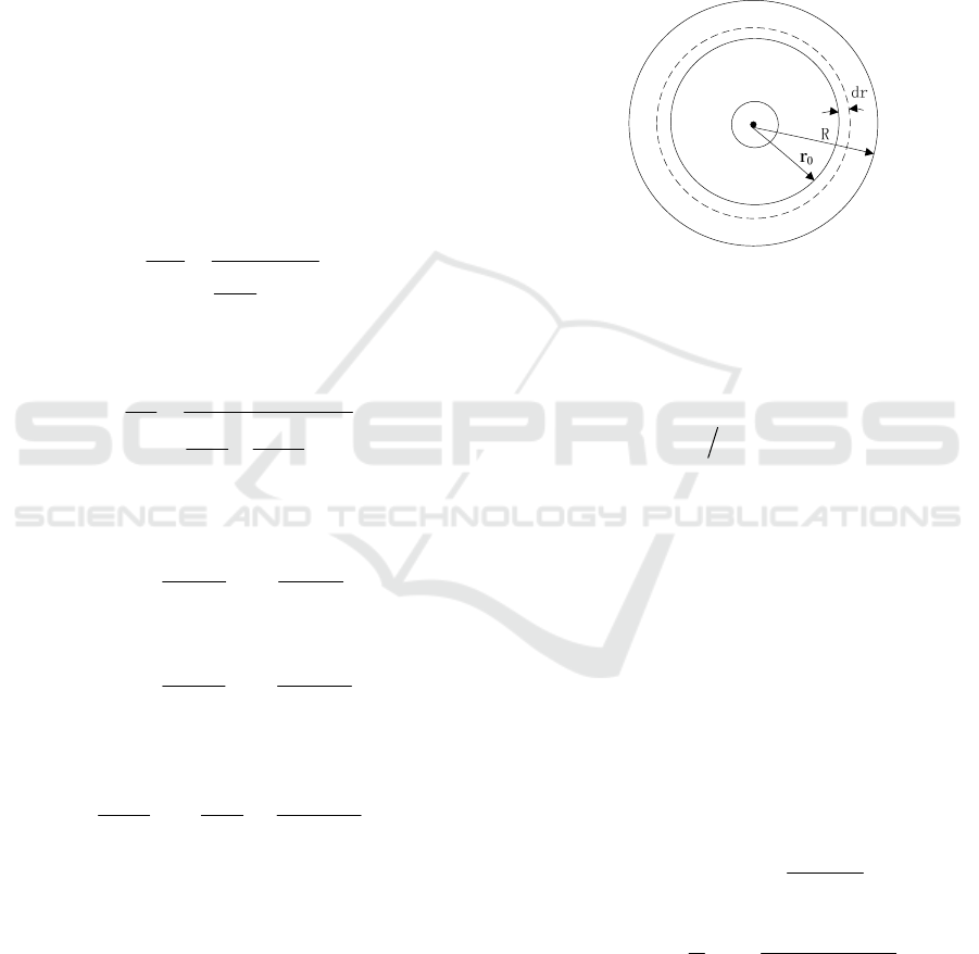
The friction outer radius of brake is defined as R, the
friction inner radius as
0
r , and the ring of the friction
surface is taken as
dr
, which is shown in Figure 1.
Figure 1: Diagram for friction surface of brake device
Assumptions: (1) the friction coefficient remains
constant during braking;(2) the thrust force of piston
on the brake disc is even.
The pistons thrust per unit area is:
()
[
]
π
⋅−=
2
0
2
rRSF
Tp
(16)
The ring
dr is taken, then the piston thrust
withstood by ring
dr
is:
drFdF
p
⋅=
(17)
The friction generated by piston ring
dr is:
rFdFdf
pss
π
μ
μ
2dr ⋅⋅=⋅=
(18)
Torque generated by piston ring
dr
is
rdrFrdfrdM
pss
π
μ
2⋅⋅=⋅=
(19)
Then the torque generated from the upper piston
thrust
Rr →
0
is:
0
2
00
2
2
0
2
2
rR
r
3
2
r
2
2
0
0
+
++
=
−
⋅=
⋅=
∫
∫
RrR
S
dr
R
S
r
rdrFrM
Ts
R
r
T
s
R
r
pss
μ
μ
πμ
(20)
In the formula:
s
μ
——friction coefficient of brake
disc,
()
vPf
s
,=
μ
ICECTT 2018 - 3rd International Conference on Electromechanical Control Technology and Transportation
104
T
S
——total piston thrust,
nSPS
LT
**=
L
P
——brake pressure;
S
——piston area;
n
——piston number.
Namely, the relationship between brake torque
and brake pressure is:
LLsS
KPP
rR
rRrR
SM =
+
++
=
0
2
00
2
n
3
2
μ
(21)
In which,
0
2
00
2
n
3
2
rR
rRrR
SK
s
+
++
=
μ
The overall nonlinear mathematical model of
aircraft brake control system in the above can be
sorted out:
⎪
⎪
⎪
⎩
⎪
⎪
⎪
⎨
⎧
Δ⋅++−=
+−=
+=
I
k
k
V
rk
P
V
k
P
P
JV
KR
f
mfmf
mft
mfmf
mf
t
qe
L
t
ce
L
L
X
g
ξ
ω
ω
θ
θ
ξ
ω
θ
θ
β
β
σσ
2
)(
2
4
4
)(
2
&&
&
&
&
(22)
Equation (22) can then be written as the
following equation of state with strict feedback,
namely:
⎪
⎩
⎪
⎨
⎧
=
+=
=+=
+
,1
33333
1
,)()(
,2,1,)()(
xy
uxgxfx
ixxgxfx
iiiiii
&
&
(23)
In which:
σ
=
1
x
)(
1
σ
ff =
JV
KR
g
X
g
=
1
L
Px =
2
L
t
ce
P
V
k
f
β
4
2
−=
t
qe
V
rk
g
β
4
2
=
θ
=
3
x
)(
2
2
3
mfmf
mf
f
ω
θ
θ
ξ
ω
&&
+−=
mfmf
mft
k
k
g
ξ
ω
2
3
=
Iu Δ=
3 THE CONSTRAINT
CONTROLLER DESIGN OF
SLIP RATE BASED ON
ASYMMETRIC BARRIER
LYAPUNOV FUNCTION
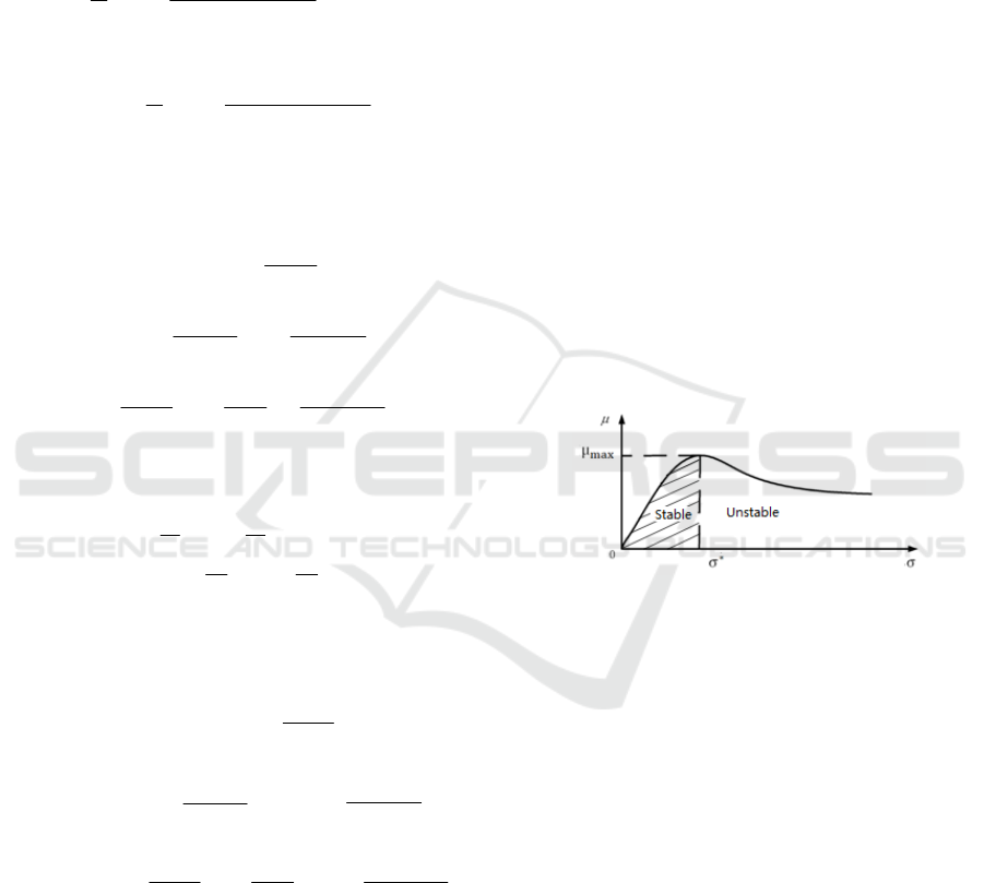
Considering the stability and instability of the slip
ratio in the aircraft anti-skid braking system, the
control method is designed as shown in Figure 2.
The slip ratio is divided into the stable and unstable
regions by the slip ratio
*
σ
corresponding to the
maximum combination coefficient
max
μ
.When
*
0
σ
<< A
is for the stable area, then
1
*
<< A
σ
for the unstable area. The purpose of
the constraint adaptive controller design for slip rate
based on asymmetric barrier Lyapunov function is to
ensure that the brake control system works at the
optimal slip ratio
*
σ
and the working range is
confined in the stable region of the tire runway
model. Meanwhile, the tracking error of slip
ratio
σ
converges to a small set of zeroes.
Figure 2: Friction model for tire runway
The error items
*
1
σσ
−=−=
d
yyS ,
iii
zxS −=
and 3,2=i are defined. During the
operation for the entire control system of aircraft
brake, the adaptive controller will stop when the
aircraft reaches the non-slip failure speed (typically
25Km / h), so the speed of aircraft
0>
X
V
.Then
for all
0,0 >>
i
gt
and 3,2,1=i is known, which
is a prerequisite for the control method.
The initial value
*
)0(
σσ
< of slip rate is
defined. The constant
25.0
1
=
c
k is selected as the
output constraint for the upper bound of slip rate,
and the output constraint
)0(
2
σ
=
c
k for the lower
bound of the slip rate. Then from the constrained
lower bound
)0()(
*
21
σσ
−=−=
cda
kytk and
The Adaptive Control of Aircraft Brake Based on Asymmetric Barrier Lyapunov Function
105

the constrained upper
bound
*
111
)(
σ
−=−=
cdcb
kyktk of
corresponding tracking error
1
S ,it is easy to judge
that both
)(
1
tk
a
and )(
1
tk
b
are bounded.
Virtual filter function
2
z
is introduced, and
from:
iiii
zz
α
τ
=+
+++ 111
&
,
)0()0(
1 ii
z
α
=
+
,
2,1=i
The first-order filter error is obtained:
iii
z
α
χ
−=
++ 11
,
1
1
1
+
+
+
−=
i
i
i
z
τ
χ
&
Based on asymmetric barrier Lyapunov function,
the following Lyapunov function is constructed:
⎪
⎪
⎪
⎪
⎪
⎩
⎪
⎪
⎪
⎪
⎪
⎨
⎧
+=
++=
+
−
+
−
−
=
2
323
2
3
2
212
2
2
2
1
2
1
2
1
2
1
2
1
2
1
1
2
1
2
1
2
1
2
1
)(
)(
log
2
)(
)(
log
2
1
SVV
SVV
Stk
tk
q
Stk
tk
q
V
b
b
a
a
χ
χ
(24)
In which,
⎩
⎨
⎧
≤
>
=
0,0
0,1
1
1
S
S
q
Based on the above analysis and combined with
the characteristics of slip control for aircraft braking
control system, the constraint control law of slip
ratio for the braking control system is obtained:
[]
⎪
⎪
⎪
⎪
⎪
⎪
⎩
⎪
⎪
⎪
⎪
⎪
⎪
⎨
⎧
⎥
⎦
⎤
⎢
⎣
⎡
−−−−=
⎥
⎦
⎤
⎢
⎣
⎡
−−
−
−
⎥
⎦
⎤
⎢
⎣
⎡
−
−
−−=
+−−=
=
==+
++++
3
3
22333
3
2
2
2
2
1
2
1
1
2
2
1
2
1
1122
2
2
111
1
1
1111
1
)
)(
(
1
)
)(
1
(
1
1
2,1
),0()0(,
τ
χ
τ
χ
α
α
αατ
SgfSk
g
u
f
Stk
q
Sg
g
Stk
q
SgSk
g
yfSk
g
i
zzz
b
a
d
iiiiii
&
&
(25)
Formula (23) is substituted into the above
formula, the output restraint control law of slip ratio
for the aircraft anti-skid braking system is obtained
based on asymmetric barrier Lyapunov function as
follows:
[]
⎪
⎪
⎪
⎪
⎪
⎪
⎪
⎪
⎪
⎪
⎩
⎪
⎪
⎪
⎪
⎪
⎪
⎪
⎪
⎪
⎪
⎨
⎧
⎥
⎦
⎤
⎢
⎣
⎡
−−
⎥
⎥
⎦
⎤
⎢
⎢
⎣
⎡
++−=
⎥
⎦
⎤
⎢
⎣
⎡
−+
−
−−
−
−
−=
+−−=
=
==+
++++
3
3
2
2
33
2
2
2
1
2
1
1
22
2
1
2
1
1
2
111
1111
42
)(
2
2
4
4
)
)(
(
44
)
)(
1
(
4
)(
2,1
),0()0(,
τ
χ
β
ω
ξ
ω
θ
θ
ξ
ω
ω
ξ
τ
χ
β
β
ββ
β
α
σα
αατ
S
V
rk
k
k
Sk
k
k
u
P
V
k
rk
V
Stk
q
JV
KSR
rk
V
rk
SkV
Stk
q
JV
KSR
rk
V
yfSk
KR
JV
i
zzz
t
qe
mft
mfmf
mf
mf
mf
mft
mfmf
L
t
ce
qe
t
bX
g
qe
t
qe
t
a
X
g
qe
t
d
g
X
iiiiii
&&
&
&
(26)
4 RESULT ANALYSIS OF
PERFORMANCE SIMULATION
Through the simulation of the entire anti-skid
braking system of aircraft with Matlab, there are the
following two hypotheses: (1) assuming that the
aircraft does not perform turning operations during
braking, but maintains a straight-line movement
landing;(2) assuming that the load and grounding
conditions of both left and right main landing gears
are the same, and the brake control system is
simplified into a single-wheel control model. Based
on the above assumptions, the control law based on
the slip rate constraint and the control law of the
traditional “PD + PBM”were simulated and
analyzed under different runway conditions. The
simulation curves of the wheel speed and the brake
pressure are seen in Figure 3 ~ Figure 5.
ICECTT 2018 - 3rd International Conference on Electromechanical Control Technology and Transportation
106
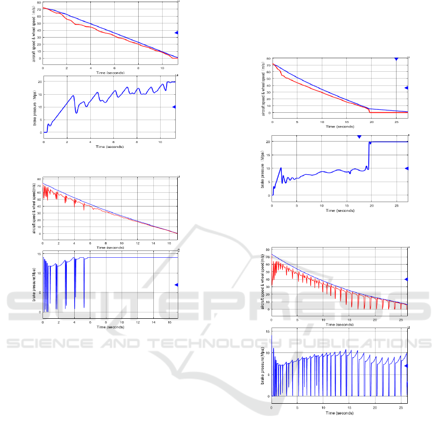
(a) Simulation curves of adaptive control law
(b) Simulation curves of traditional PD + PBM control law
Figure 3: Simulation results under dry runway conditions
It can be seen from Figure 3, the adaptive control
algorithm based on the slip rate constraint can be
compared with the traditional PD + PBM control
algorithm under the condition of dry runway. The
brake control system under the adaptive control
algorithm can be adjusted in the maximum range (0-
21Mpa) within the regulation of brake pressure. The
maximum can be adjusted to 20.8Mpa, so as to
obtain a larger braking torque, braking efficiency is
higher, the slip rate of about 95% efficiency, and
braking distance of 372m; and throughout the
braking process, the system can work
near the optimal slip ratio corresponding to the
maximum binding coefficient and always stay in a
stable region of the curve
σ
μ
−
. The slip rate
always fluctuates around 0.13 except for the initial
slow pressure rise until the anti-slip is released.
Under the traditional PD + PBM control algorithm,
the maximum braking pressure is limited to
13Mpain order to prevent torque charge, the
utilization rate of the ground is reduced, the system
cannot obtain the maximum braking torque, and the
braking distance increases to 574.4mrelative to the
adaptive control algorithm, slip rate efficiency is
about 85.5%, and braking efficiency is significantly
reduced.
(a) Simulation curves of adaptive control law
(b) The Simulation Curves of Traditional PD + PBM
Control Law
Figure 4: Simulation results under wet runway conditions
It can be shown in Figure 4 that the combination
coefficient provided by the ground reduces under
wet runway conditions. To balance the matching
torque, the brake pressure provided by the brake
control system reduces accordingly. The maximum
brake pressure is down to about 8Mpa. However,
during the entire braking process, the brake pressure
under the adaptive control algorithm based on the
slip rate constraint can respond quickly and can be
accurately adjusted within a small range. In addition
to the slowly rising phase of the initial pressure, the
slip rate always fluctuates around 0.15 until the slip
at the 19.4s is released. No deep slippage appears in
The Adaptive Control of Aircraft Brake Based on Asymmetric Barrier Lyapunov Function
107
the process of entire braking, which can maintain a
higher braking efficiency. The braking efficiency is
about 88% and the braking distance 711.8m; but
under the wet runway condition, the wheel in the
traditional PD + PBM control is always in a slippery
condition, and many deep slippage occurs, which
makes the tire more wear and tear and reduces the
service life of the tire and the braking efficiency.
The braking efficiency is 74.8% and the braking
distance is 871.1m.
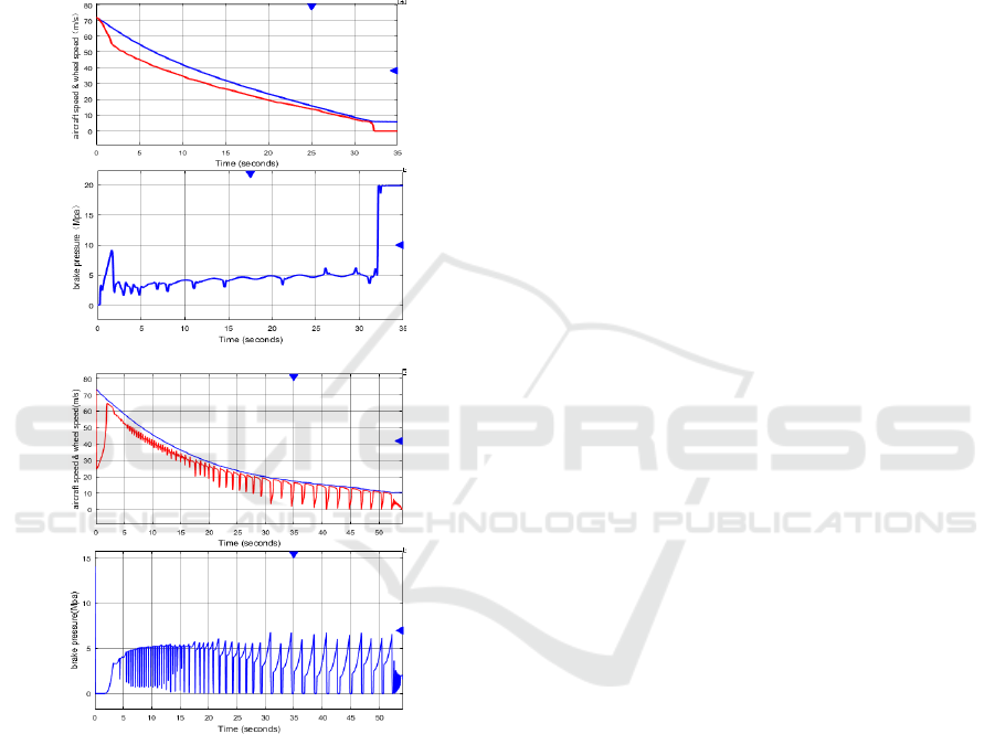
(a) Simulation curves of adaptive control law
(b) Simulation curves of traditional PD + PBM control law
Figure 5: Simulation results under Ice runway conditions
As can be seen from Figure 5, the combination
coefficient provided by the ground significantly
reduces under the ice runway conditions. In order to
prevent the occurrence of bodily defects and locking,
the maximum braking force of the brake device
applied by the brake control system is significantly
reduced, about 5Mpa. However, the adaptive control
algorithm based on slip rate constraint is smoother
throughout the braking process and does not appear
deep slipping. The braking time is 32.8s and the
braking distance is 883.2m. However, the braking
time of the conventional PD + PBM control law is
52.3s and the braking distance is 1543m. The
response of the brake pressure regulation is slow
during the entire braking process. There is deep
slippage, which is worse than the adaptive control
algorithm based on the slip ratio constraint.
5 CONCLUSION
Based on the analysis of the non-linear mathematic
model for the aircraft anti-skid braking system, the
author puts forward an adaptive control method of
slip ratio constraint based on asymmetric barrier
Lyapunov function. The simulation tests show that
under different conditions of dry, wet and ice
conditions:
(1) The anti-skid braking system of aircraft has
the characteristics of high-order non-linear
parameters such as time-varying. Due to the
influence of runway environment, design parameters
of driving mechanism and actuator, aerodynamics
and other factors, linear control theory cannot
guarantee that brake operating point is located in a
stable region.
(2) Compared with the traditional PD + PBM
control algorithm, the adaptive control of slip rate
constraint based on the asymmetric Lyapunov
function can quickly adjust the brake pressure so
that the system can maintain the curve
σ
μ
−
under
all conditions in the stable area, the system can make
full use of the frictional resistance provided by the
ground, make the whole brake control system and
the wheel have a good match, and reduce the
frequency of skidding, shorten the braking distance
and improve the braking efficiency.
(3) Through the application of adaptive control
method, no slippage or lock-up occurs, the wear on
the braking device is reduced and the service life of
the brake disc is increased, thereby the economy of
use is improved.
To sum up, the adaptive control method of slip
rate constraint asymmetric barrier based on
Lyapunov function is a design method with high
performance and economy, which will be an
important evaluation index in the field of civil
aircraft development. Therefore, this method is
proposed to provide the direction and basis for
engineering application in the field of adaptive full-
regulation control of aircraft skid braking system.
ICECTT 2018 - 3rd International Conference on Electromechanical Control Technology and Transportation
108

REFERENCES
AC NO.25-7A , Flight Test Guide for Certification of
Transport Category Airplanes.FAA.
TANELLI M, ASTOLFI A, SAVARESI S M,
2008.Robust nonlinear output feedback control for
brake by wire control systems[J]. Automatica. Vol.44,
p:1078~1087.
R.Babuska, H.B.Verbruggen, 1996.An Overview of Fuzzy
Modeling for Control. Control Engineer Practice.
p:1593~1606.
MI C T, LIN H, ZHANG Y, 2005.Iterative learning
control of antilock braking of electric and hybrid
vehicles[J]. IEEE Transactions on Vehicular
Technology. Vol.54, p: 486-494.
BASLAMISLI S C,K SE I E, ANLAS G,2007.Robust
control of anti-lock brake system[J]. Vehicle System
Dynamics, Vol. 45,p: 217-232.
TANELLI M, FERRARA A, 2013. Switched second-
order sliding mode control with partial information:
Theory and application[J]. Asian Journal of Control.
Vol.15,p: 20-30.
CHO D-W, CHOI S, 1999.Control of wheel slip ratio
using sliding mode controller with pulse width
modulation[J]. Vehicle System Dynamics. Vol.32,p:
267-284.
CHOI S, CHO D-W, 2001.Design of nonlinear sliding
mode controller with pulse width modulation for
vehicular slip ratio control[J]. Vehicle System
Dynamics, Vol.36,p: 57-72.
HEBDEN R G, EDWARDS C, SPURGEON S K,
2004.Automotive steering control in a split-manoeuvre
using an observer-based sliding mode controller[J].
Vehicle System Dynamics, Vol.41,p:181-202.
Shi Wei, Liu Wensheng, Chen Jianqun, 2012.Application
of Model Free Control Technology on the Aircraft
Anti-skid Brake Systems. Computer Measurement &
Control. Vol.20,p:1552-1554.
Wang Jisen, 2001.Nonlinear Control Theory and its
Application to Aircraft Antiskid Brake Systems [D].
Doctoral Thesis of Northwestern Polytechnic
University.
Qiu Yanan, 2016.Constrained Control for Nonlinear
Systems and its Applications [D]. Doctoral Thesis of
Northwestern Polytechnic University .
Chen Zhaoguo, Li Zhigang, Huang Qi, 2005.Study on the
Pressure Characteristics of the Electro-hydraulic Servo
Valve of Two Nozzle Baffles. [J]. Engineering
Machinery.Vol. 36 ,p:28-30.
Chen Xiaolei, 2016.Research on Control Strategy of
Electromechanical Actuation Servo System for More
Electric Aircraft [D]. Doctoral Thesis of Northwestern
Polytechnic University .
SU Jun-ming, etc., 2011. Effects of braking velocity and
pressure on aircraft brake discs' friction and wear
properties [J]. Materials Science and Engineering of
Powder Metallurgy. Vol. 16,p:212-217.
Xiong Xiang, 2004.Investigation of Braking Properties of
Carbon-Carbon Composites [D]. Doctoral Thesis of
Central South University.
The Adaptive Control of Aircraft Brake Based on Asymmetric Barrier Lyapunov Function
109
