
Solar-Tracking Phone Charger
Haoyu Liu, Esther Xu, Josiah Soegiharto, Mohammed Bamhraz and Daisy Zhao
The University of British Columbia Vancouver Canada
Corresponding author: 2316544785@qq.com
Keywords: Solar energy, temperature sensors, the solar panel, store, environmental concerns.
Abstract: This project uses solar energy from the light, then stores it and finally converts it into electric energy. The
electric energy is used to charge any electronics. In our project solar panels absorb the energy and
temperature sensors detect the temperature and change the direction of the solar panel to follow the
direction of the light. Thus, temperature sensor plays an important role in our project. Then the electricity
stores in the capacitor and go into the electronics by wire. In the introduction, the main steps of the project
are provided, similarly, the purpose and importance of project are shown. In the discussion section, the
details of coding, solidwork drawing and actual work are examined. The experimental setup lists the
materials that are used in the project and show how the process is carried out to achieve the goals.
1 INTRODUCTION ON THE
PROJECT CONCEPT
The increasing functionality and performance of
mobile phones increases the demand for a power
recharging and storage technology that can allow
phone batteries to last longer and to be recharged
more practically. The device that we made in our
project provides a way of recharging and storing
power for mobile phones that satisfies this
increasing need. Our device is a portable external
battery (also known as power bank) that contains
embedded solar panels, which allow it to be
recharged using solar energy. The battery can orient
itself to face towards the light source that yields the
highest energy. Due to its capacity of being recharge
mobile phones and thus is very helpful when
traveling long distance. Furthermore, its capability
of being recharged by solar energy allows the
mobile phone to be moved around while it is being
charged, provided that the solar panels are exposed
to enough light or some power remains in the
batteries, unlike the charging process using electrical
energy. If light is not available, the device can be
recharged using a conventional power socket. The
device is composed of components that are
compatible with the Arduino hardware and soft ware;
its casing is 3D printed.
2 EXPERIMENTAL SET UP
2.1 Design and drawing
Firstly, all parts needed were ordered online, after
the parts were picked up, it’s necessary to measure
the dimension of parts in order to design the shape,
electrical part and mechanical part by drawing by
hand. Then the solidworks is needed to setup the 3D
shape, all dimensions should suit the real parts.
2.2 Mechanical of solar tracker
Tracker is a dual axis tracker, meaning it tracks in
both X -axis and Y-axis. To put it into even more
simple terms, it goes left, right, up, and down. This
means once the tracker was set up nothing need to
change or adjust, since anywhere the sun moves the
tracker will follow. This also impresses people at
parties because a flashlight can be tracked around.
This method gives the best results for power
generation.
2.3 Assemble of parts
To start out the Servos are attached to their mounts
Liu, H., Xu, E., Soegiharto, J., Bamhraz, M. and Zhao, D.
Solar-Tracking Phone Charger.
In 3rd International Conference on Electromechanical Control Technology and Transportation (ICECTT 2018), pages 23-26
ISBN: 978-989-758-312-4
Copyright © 2018 by SCITEPRESS – Science and Technology Publications, Lda. All rights reserved
23
Open up the bag the Servo came in. There will
be three screws. Two pointy wood screws with large
heads, and one small machine screw. Place the
single machine screw to the side, we won't be using
it now.
Pick up the large round wooden piece without an
arrow on it. The Servo is mounted on the bottom of
the piece.
Line the servo up with the screw holes, and then
carefully use the two Servo screws to secure it in
place. Once in place give it a little tug to make sure
it's secure. Find the second wooden Servo mount.
We'll be doing the same thing here with our second
Servo. Mount it on the "back" of the mount with the
two screws it came with.
Grab the very base plate, the four legs, and the
large round piece that now has a Servo attached to it.
You'll also need 8 of the 6-32 Screws and 8 nuts.
First attach the four legs to the round servo
holder. The Servo needs to be inside all the legs,
between the the base plate and the round servo
holder. Don't tighten the screws all the way, leave
them a bit loose.
Now fit the four legs into the base plate. Make
sure that when you do this the servo wire is
positioned so that it's coming out towards the back
where all our electronics will be.
Once all our legs are screwed into the base plate
go back and tighten the four screws that attach the
legs to the round servo holder.
Lastly, put the four rubber feet on the bottom of
the base plate so that the screw heads don't scratch
up your work surface.
At this time you can also put together the LED
display holder. The LED display just fits between
the two wooden holders and is secured by two
screws and nuts.
Grab the large solar array face. It's the one that
says "Solar Cell Here" on it. We'll also need the two
triangle wings, the small rounded corner square
piece, and the two small sensor divider pieces. To
connect it all we'll need six 6-32 Screws and nuts.
Put the face plate on the table in front of you so
that you can read the words. Attach the triangle wing
piece with the servo arm on the right side, and the
other triangle wing piece onto the left side. We want
the plastic servo arm to be facing the inside.
Use four screws and nuts to hold that together.
Now use the three remaining pieces to build the
sensor divider. Rounded square first, then the tall
skinny piece, and finally the longer piece with the
two screw T slots. Once it's all together use two
screws and nuts to secure it.
Servos move in 180 degrees. The Servo knows
where "zero" degree is and where "180" degree is.
Since we don't want or need full 180 degree range
on our servos we want to set our "zero" degree to
some very specific locations.
Start with the Base plate Servo. Without using
the little screws push the Servo Arm that’s attached
to the Center into the servo. This may take a little
effort, so you may wish to brace the
servo with your other hand. Once together,
slowly rotate the Center counter clockwise until
there servo stops. This is "zero" degrees on the
Servo.
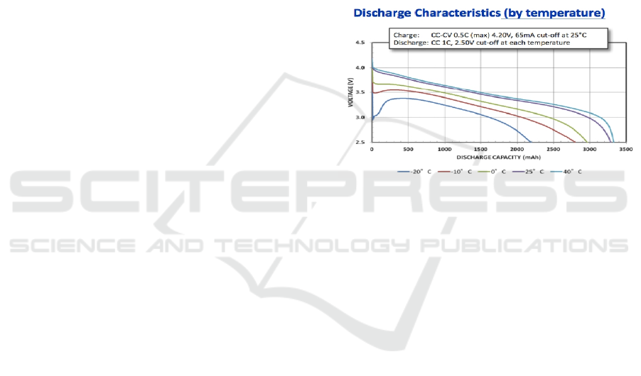
The relationship between battery voltage and
capacity is shown in Figure 1.
Figure 1: Voltage vs. Discharge capacity.
2.4 Assemble of Sensors
Take Connectors. Snip off the ends of the wires and
then strip the wires.
Grab four Light Sensitive Resistors. The legs are
way too long. Remove 2/3rds of their legs.Push one
Light Sensitive Resistor into each of the four
Connectors. The should go in easily.Thread one
Female JST Connector through each of the four
holes around the Sensor Divider.
Now have 8 wires handing down through the
Top around the Sensor Divider.
A diagram of the full circuit with the battery
indicators is shown in Figure 2.
ICECTT 2018 - 3rd International Conference on Electromechanical Control Technology and Transportation
24
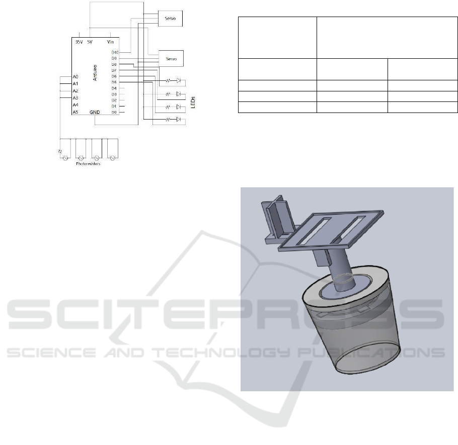
Figure 2:The full circuit with the battery indicators.
3 MATERIALS
Breadboard, Photoresistors, Ardunino, Jumper,
Servo Motor, Resistor (10k ohm), Tactile Switch,
Diode,LED,Voltage regulator switch,Porttermind
Block 2x5,Porttermind Block 2x4,
Cable Wraps,Screws.
4 RESULTS
The theoretical output voltage of the circuit to the
USB boost converters, which powers the Arduino
board and the phone, is 5V. The battery capacity is
3400mAh.
The tracking system is very sensitive as it is
capable of responding to small changes in angle of
light in high speed.
The functionality of the device makes it useful
when one is travelling long distances, or to places
where access to the power socket is limited. The
device can also double as both a house ornament and
renewable power supply. It can also be useful for
outdoor events, such as an outdoor party.
The values of the voltages of the battery at its
corresponding power remaining in the battery used
for the coding of the battery indicator may be very
slightly inaccurate. These values changes as the
temperature of the battery changes, and in the code
only the values at temperature of 25 degrees is used.
Table 1:Table of results
Length of Time Needed to Fully
Charge a Running Samsung Galaxy
S5 with 73% Battery
(minutes)
DU Battery
Save
r
Battery Doctor
(
Batter
y
Saver
)
Char
g
in
g
circuit 35 40
Power socket 35 40
Laptop 40 61
5 SOLIDWORK DRAWING
The Solidwork Drawing is shown in Figure 3.
Figure 3: a sample design of solidworks.
6 DISCUSSION
The solar tracking system is able to rotate 180
degrees horizontally and vertically and its
effectiveness in tracking the light is limited to this.
The solar tracking system will not be able to follow
the light after it reaches its maximum.
The speed of the charging circuit in charging the
cell phone, according to two phone battery saving
applications; the DU Battery Saver and Battery
Doctor (Batter Saver), is as fast as the power socket,
and faster than charging by connecting the phone to
the laptop. According to DU Battery Saver, when
the phone battery is at 73%, charging the phone
using the power socket, the charging circuit and the
by connecting it to the laptop takes 35 minutes, 35
Solar-Tracking Phone Charger
25

minutes and 40 minutes, respectively. According to
Battery Doctor (Battery Saver), it takes 40 minutes,
40 minutes and 61 minutes to charge the phone
using the power socket, the charging circuit and the
by connecting it to the laptop, respectively, when the
phone battery is at 73%.
7 CONCLUSION AND FUTURE
APPLICATION
One of the most important features of this project is
that it is able to track the source of energy. It
incorporates a solar tracking system that is able to
turn 360 degrees in both vertical and horizontal
direction. This helps to get a great amount of solar
energy. The solar energy is converted to chemical
energy and stored in the battery. In this project not
only can charge the electronics but also can indicate
the remaining amount of the battery. This prevent to
overcharging the electronics thus protect the
electronics. In the future study, improvement of the
shape can be made to increase the efficiency of the
converting process.
ACKNOWLEDGEMENTS
Our team would like to express their appreciation to
Dr. Ray Tehari, school of engineering, The
University of British Columbia Okanagan campus
for his valuable and high professional support. Our
Team also wish to acknowledge the TAs and
professor from Electrical and engineering
department from their valuable help.
REFERENCES
Awingot, A. R. (2016). A solar radiation tracker for solar
energy optimisation. British Journal of Applied
Science & Technology, 14(4), 1.
Juang, J., Radharamanan, R., & Beaver, J. (2013). A low
cost solar tracker design for renewable energy.
Journal of Management & Engineering Integration,
6(2), 15.
Wei, W., & Shaoyuan, L. (2012). Model predictive control
of 2-axis solar tracker for solar energy system. Paper
presented at the 4177-4182.
ICECTT 2018 - 3rd International Conference on Electromechanical Control Technology and Transportation
26
