An Alternative Method for Kinematic Modelling Applied to the Human
Joint Position
Bibiana Hern
´
andez-Hern
´
andez
1,2
, Cesar Ramos-Villa
1,2
, Dulce Martinez-Peon
1,2
,
Eduardo Torres-Sarmiento
1,2
and Ernesto Olgu
´
ın-D
´
ıaz
3
1
Division of Studies and Postgraduate Research, Institute of Technology of Nuevo Leon, Mexico
2
National Technological Institute of Mexico, Mexico
3
Robotics and Advanced Manufacturing Group, Cinvestav, Coahuila, Mexico
Keywords:
Kinematic Modelling, GRyMA Methodology, Biomechanics.
Abstract:
The kinematic description of a mechanical structure is an essential part of the motion analysis. In human-
like structures, kinematics works as a biomechanical base for the analysis of the human motion in areas
like rehabilitation and sports. While nowadays the standard is based on the Denavit-Hartember convention,
which has been defined for industrial mechanical use, this approach may need virtual reference frames when
having non orthogonal systems and complex geometries like human body. This work presents a kinematic
analysis focused on lower limbs using an alternative to the Denavit-Hartenberg convention for reference frames
assigment in kinematic modelling, called the GRyMA methodology. Finally, the paper also shows Matlab
c
-
based simulation of a CAD model emulating the human lower limbs motion. The kinematic analysis could be
used in the assessment of the joint position of individuals with some walk or sports disability, and therefore
also in the correct treatment or posture improvement.
1 INTRODUCTION
Biomechanics is the science that involves the study of
the mechanical features of living organisms, mainly
focused on human anatomy, (Hall, 2012). There are
two important concepts within this discipline: Ki-
nematics, a part of mechanics field that studies the
motion of objects regardless of the forces applied to
them, including displacement, velocity and accelera-
tion; and Kinetics, which studies the forces that pro-
duce the body motion and its changes, (Bergmann and
Peterson, 2011).
Human motion analysis observes in detail the hu-
man motion in order to gather quantitative informa-
tion about the mechanics of the body when executing
different tasks. In this branch, the study of the human
gait is very important because of its use in clinical ma-
nagement like planning and treating individuals with
some walking or sports disability; or to estimate the
joint positions of a healthy runner, (Lu and Chang,
2012). The kinematic field provides an accurate des-
cription of the human motion and it is fundamental to
understanding its biomechanics, (Knudson, 2007).
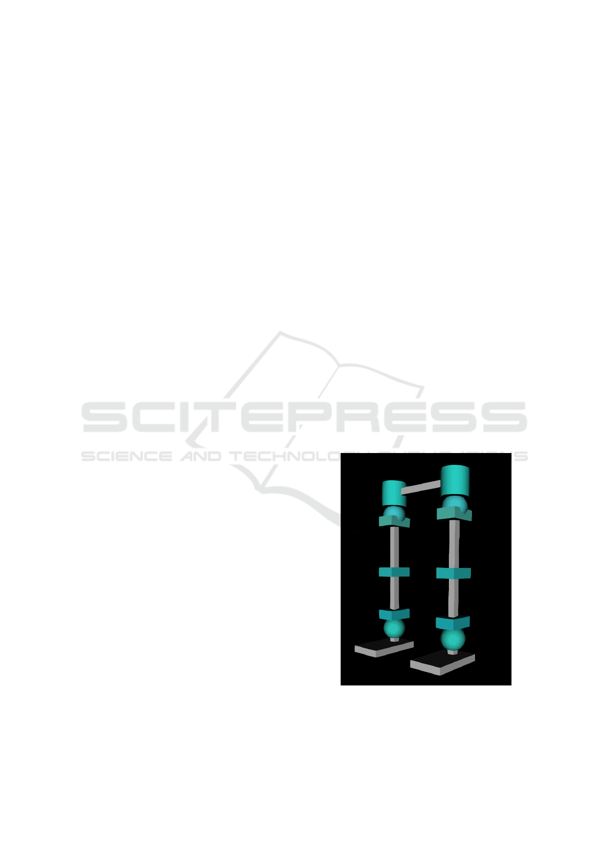
In sports, posture analysis is fundamental and
Figure 1: 12 DoF lower limbs model (6 for each leg).
must be obtained precisely. Some analysis techni-
ques includes numerical methods like small series of
kinematic patterns, (Bharatkumart et al., 1994), pre-
Hernández-Hernández, B., Ramos-Villa, C., Martinez-Peon, D., Torres-Sarmiento, E. and Olguín-Díaz, E.
An Alternative Method for Kinematic Modelling Applied to the Human Joint Position.
DOI: 10.5220/0006937301390144
In Proceedings of the 6th International Congress on Sport Sciences Research and Technology Support (icSPORTS 2018), pages 139-144
ISBN: 978-989-758-325-4
Copyright © 2018 by SCITEPRESS – Science and Technology Publications, Lda. All rights reserved
139

dictions of length patterns of in-vivo ligaments with
global position vectors, (Lewis and Lew, 1978), mo-
dels estimation for anatomical joints with minimum
squared error, (Sommer and Miller, 1980). Scott,
purpose a software to analyse musculoskeletal struc-
tures from input parameters provided by user where
kinematics is solved using transformations (orthogo-
nal translations and rotations) between axes having
as a reference the HUMERUS and ULNA segments,
(Delp and Loan, 1995). Hanavan takes advantage of
computers as an useful tool when modelling human
body and purposes a 15 geometric solid mathemati-
cal model for body modeling, based in antropometric
dimensions, and describes body positions with Euler
angles, (Hanavan JR, 1965); while Bogert and their
colleagues designed a software system able of calcu-
lating forward and inverse kinematics of 44 degrees of
freedom (DoF), (Bogert et al., 2013). Baldisserri and
Castelli made a 3D kinematic model considering four
bones (tibia, fibula, talus and calcaneus) to emulate
passive motion; the analysis was made using Denavit-
Hartenberg transformation matrices, (Baldisserri and
Castelli, 2010).
In addition to the aforementioned techniques,
there are alternative marker-based methods, (Rab
et al., 2002) that can be subdivided in two catego-
ries: contact based techniques, including accelerome-
ters and goniometers sensors, and non-contact based
techniques using active LEDs (Light-emmiting dio-
des) or passive markers (tags), (Prakash et al., 2015).
Nonetheless, there is still much to do in technologi-
cal improvement, mathematical modelling of muscu-
loskeletal system and more techniques to quantify and
reduce measurement errors, (Lu and Chang, 2012).
In Kinematics, the most common method to des-
cribe the link structure of an articulated body is the
well known Denavit-Hartenberg method, (S.Kajita,
2014); although it is not always practical when ana-
lysing complex systems. Therefore the present work
proposes an alternative method in the assignation of
reference frames known as GRyMA methodology,
(B
´
aez and Olgu
´
ın-D
´
ıaz, 2013).
This work is organized as follows. In Section 2,
the alternative approach of the forward kinematics is
explained, detailing the algorithms to allocate the re-
ference frames as well as the structure of the homo-
geneous tranformations. Section 3 presents a case of
study representing the basic motion of human lower
limbs by appliying the alternative GRyMA methodo-
logy. In Section 4, simulation on a 3D CAD model
is presented using the GRyMA procedure in order to
show the simplicity and functionality of the proposed
method. Finally, the conclusions are stated in Section
5.
2 METHODOLOGY
DESCRIPTION
The most common method used to calculate kinema-
tics within a kinematic chain consisting of articulated
bodies is by using order 4 homogenous transformati-
ons as:
A =
R d
0 1
∈ SE(3)
Each of these transformations represents a rotation
(through the 3 DoF Rotation matrix R ∈ SO(3)) and a
translation (through the 3 DoF displacement d ∈ R
3
).
Then by assigning a reference frame (normally under
the right hand rule) in each rigid body in the kine-
matic chain, it arises an homogenous transformation
between these frames upon which any position and
hence its time derivative values can be calculated.
These homogeneous transformations needs 6 li-
neally independent parameters to be described. In
this sense the Denavit-Hartenberg convention impo-
ses two restrictions on each two consecutive frames,
which reduces the complexity of each homogeneous
transformation to only four parameters. Even more,
for articulated bodies in a kinematic chain, only one
of these parameters is variable becoming the relative
joint value, while the remanent 3 constant parame-
ters describes the kinematic chain. This methodology
has been proven to be very useful and simple even in
complex systems. However it has been designed spe-
cifically for mechanical systems where the two con-
straints needed are always fulfilled.
These constraints are seldom fulfilled on complex
systems like biomechanical ones, for which most of
the time an additional virtual frame in each articula-
tion has to be included to guarantee the validity of the
methodology. In these cases, the number of parame-
ters needed to describe a single articulation increases
to 8 (with only one variable) which renders the ho-
mogeneous transformation more complicated than the
original of 6 DoF without the DH convention.
An alternative approach for the assignation of
these frames is the GRyMA method (After Grupo de
Rob
´
otica y Manufactura Avanzada), where the origin
of every reference frame Σ
i
is placed at any user cho-
sen point along the articulation axis, and always pa-
rallel to the inertial frame at the home position of the
system. Then the homogeneous transformation of the
child/parent frames (A
i
: Σ
i−1
→ Σ
i
) can be expressed
as, (B
´
aez and Olgu
´
ın-D
´
ıaz, 2013):
A
i
=
R(λ
Ri
, q
i
(t)) d
i
+ λ
Ti
q
i
(t)
0 1
(1)
icSPORTS 2018 - 6th International Congress on Sport Sciences Research and Technology Support
140
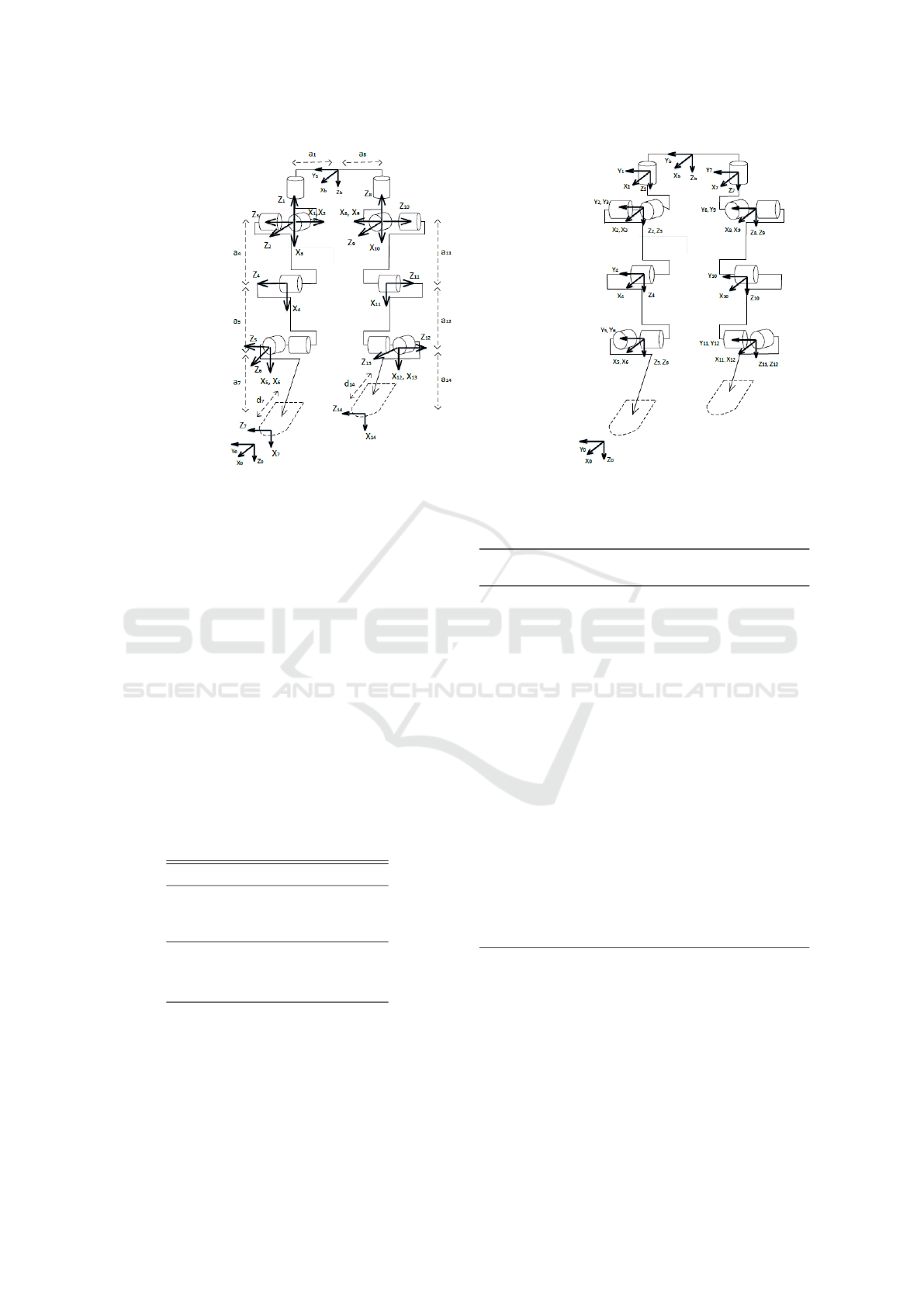
(a) using DH convention (b) using GRyMA methodology
Figure 2: Reference frames, note that in figure b all the axes including global reference frame are oriented in the same
direction.
where q
i
is the variable generalized coordinate corre-
sponding to the articulation; the 3D distance d
i
∈ R
3
in coordinates of the parent frame i-1, is the con-
stant position of the origin of the child’s frame; the
unit director vectors λ
Ri
and λ
Ti
(composed of 3 ele-
ments each), also in coordinates of parent frame, de-
fine whether the articulation is rotational or prismatic
(respectively) and the rotation matrix is defined upon
the axis/angle representation.
Then the mode and direction of the articulated
joint is given by the kinematic director λ
i
(θ
i
) =
(λ
T
Ri
, λ
T
Ti
)
T
∈ R
6
, where λ
i
can be codified with the
scalar parameter θ
i
according to the Table 1, using
only 4 constant parameters and one variable for each
articulation. The GRyMA methodology uses Algo-
rithm 1 to place the reference frames.
Table 1: Kinematic director.
θ 0 1 2 3 4 5 6
0 1 0 0 0 0 0
λ
Ti
0 0 1 0 0 0 0
0 0 0 1 0 0 0
0 0 0 0 1 0 0
λ
Ri
0 0 0 0 0 1 0
0 0 0 0 0 0 1
Where:
θ Indicate which axis will have a movement
λ
Ri
Indicate rotation movement
λ
Ti
Indicate translation movement
Algorithm 1: GRyMA methodology for Frame Assignment,
(B
´
aez-Golubowski, 2015).
1: Identify the motion axes of the articulations in the
system.
2: Assign the root (not always the inertial one) re-
ference frame Σ
0
in a way that the position and
orientation are strategically defined with the mo-
tion axes of the system. Allocating it along the
first articulation is useful because it would sim-
plify the parameters.
3: Assign each reference frame Σ
i
of the i-link with
the origin along the articulation axis and taking
the same orientation as defined in the inertial
frame. If possible the origin may be allocated to
intersect the motion axis of the parent frame too,
in order to make one of the three position para-
meters equal to zero and simplify the parametric
definition.
4: Define the distance vector d
i
∈ R
3
from the Σ
i−1
frame to the Σ
i
frame.
5: Codify the direction parameter θ according to Ta-
ble 1.
3 EXPERIMENTAL WORK
In this section, GRyMA methodology is applied to the
3D study case model, which stands for 7 segments of
the human lower limbs.
The assignment of the reference frame Σ
0
defines
the orientation of the other frames at initial or home
An Alternative Method for Kinematic Modelling Applied to the Human Joint Position
141

position. The restriction is that all articulation axes
have to be aligned to any axis of the frame Σ
b
in order
to simplify the analysis to 4 constant parameters and
one joint variable, shown in Table 2 according to the
Table 1, for the same case of study. Figure 2(b) shows
the corresponding frame assignment.
Table 2: GRyMA kinematic parameters.
Joint d
x
d
y
d
z
θ Σ Parent
1 d
x1
d
y1
d
z1
6 Σ
b
2 d
x2
d
y2
d
z2
4 Σ
1
3 d
x3
d
y3
d
z3
5 Σ
2
4 d
x4
d
y4
d
z4
5 Σ
3
5 d
x5
d
y5
d
z5
5 Σ
4
6 d
x6
d
y6
d
z6
4 Σ
5
7 d
x7
d
y7
d
z7
6 Σ
b
8 d
x8
d
y8
d
z8
4 Σ
7
9 d
x9
d
y9
d
z9
5 Σ
8
10 d
x10
d
y10
d
z10
5 Σ
9
11 d
x11
d
y11
d
z11
5 Σ
10
12 d
x12
d
y12
d
z12
4 Σ
11
The homogeneous transformation matrixes that
define the position and orientation of the links refe-
rence frames are obtained after equation (1). The ho-
mogeneous transformation matrix of the final effector
frame respect the root frame, its obtained again after
expression (2).
T =
n
∏
i=1
A
i
i−1
=
R
e
(q) d
e
(q)
0 1
(2)
Given this, the value of position d
e
and orienta-
tion R
e
of the final effectors (also known as Forward
Kinematics) is obtained as functions of the joint coor-
dinates (θ
1
. . . θ
14
).
4 RESULTS
To test the kinematics results obtained by the GRyMA
methodology, a 3D CAD model for the 7-segment
model was made using V-Realm Builder tool of Mat-
lab
c
to simulate the motion in human lower limbs.
The joint structure shown in Figure 1 has 12 actuated
DoF (the 6 DoF of the root frame has been constraint
to have no motion), the hip joint has 3 DOF which al-
lows the abduction-adduction, flexion-extension and
rotation of the upper leg segment; the knee joint has
1 DoF for the flexion-extension lower leg segment;
and the ankle is provided with 2 DOF, including the
frontal flexion-extension and rotation of the foot.
The block diagram made in Simulink
c
to simu-
late the positions of the links can be appreciated in
Figure 3.
Figure 3: Simulation block diagram.
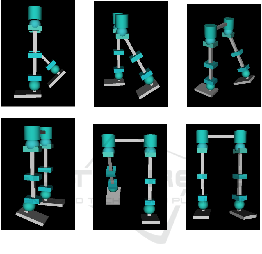
Anthropomorphic measures were taken into ac-
count to set the lenght of the links of the 3D CAD
model as well as the tridimensional translation d
i
∈
R
3
for the reference frames of the system. Hu-
man motion in lower limbs like rotation, extension-
flexion, adduction-abduction and inversion-eversion
were simulated. The results of the implementation of
the GRyMA methodology are presented in Figure 4,
which displays an aproximation of the desired beha-
vior of the system in the virtual world when perfor-
ming different postures.
5 CONCLUSIONS
The Denavit-Hartenberg convention is the most com-
mon mathematical methodology in the assignment of
frames to produce the kinematic study of articulated
rigid multi-bodies systems but when it comes to more
complex systems, auxiliar reference frames are nee-
ded, which can generate confusion when defining the
centers of mass of the links, besides it makes the kine-
matic analysis harder by elevating the parameters by
4 each time an auxiliar frame is used.
One of the advantages of the GRyMA methodo-
logy is that the allocation of the children frames can
be done (by definition of the GRyMA methodology)
in such a way that also intersects the motion axis of
the parent frame, this allows to make one of the three
position parameters equal to zero and simplify the pa-
rametric definition.
Having a simplified homogeneous transformation
becomes handy for the solution of the inverse kine-
matics, as an alternative to existing solutions.
ACKNOWLEDGEMENTS
We would like to thank CONACYT for the scho-
larships granting with numbers 612807, 605806 and
607608, which supported the studies of the students
during their master.
icSPORTS 2018 - 6th International Congress on Sport Sciences Research and Technology Support
142
(a) (b) (c)
(d) (e) (f)
Figure 4: Representation of different movements in virtual model by applying the GRyMA methodology to the kinematic
modelling: a), d) Sagittal displacement of the knee and the ankle respectively; b), e) Sagittal displacement of the hip; c)
Frontal displacement of the hip; f) Horizontal displacement of the hip and Frontal displacement of the ankle.
REFERENCES
B
´
aez, G. and Olgu
´
ın-D
´
ıaz, E. (2013). Control cinem
´
atico en
el espacio operacional de un robot b
´
ıpedo en fase de
doble soporte. In Congreso Internacional de Control
Autom
´
atico, pages 502–507. AMCA and CICESE.
B
´
aez-Golubowski, G. I. (2015). S
´
ıntesis del ciclo completo
de la marcha b
´
ıpeda de un robot humanoide. Master’s
thesis, Centro de Investigaci
´
on y de Estudios Avanza-
dos del Instituto Polit
´
ecnico Nacional CINVESTAV.
Baldisserri, B. and Castelli, V. P. (2010). A new spatial kine-
matic model of the lower leg complex: A preliminary
study. In Pisla, D., Ceccarelli, M., Husty, M., and Cor-
ves, B., editors, New Trends in Mechanism Science,
pages 295–302. Springer, New York.
Bergmann, T. and Peterson, D. (2011). Chiropractic Techni-
que. MOSBY.
Bharatkumart, A. G., Daigle, K. E., Pandy, M. G., Cait,
Q., and Aggarwalt, J. K. (1994). Lower limb kinema-
tics of human walking with the medial axis transfor-
mation. IEEE Workshop on Motion of Non-rigid and
Articulated Objects, pages 70–76.
Bogert, A. J. V. D., Geijtenbeek, T., Even-Zohar, O., Steen-
brink, F., and Hardin, E. C. (2013). A real-time system
for biomechanical analysis of human movement and
muscle function. Medical & Biological Engineering
& Computing, pages 1069–1077.
Delp, S. L. and Loan, J. P. (1995). A graphics-based soft-
An Alternative Method for Kinematic Modelling Applied to the Human Joint Position
143

ware system to develop and analyze models of musco-
loskeletal structures. Computers in Biology and Me-
dicine, 25:21–34.
Hall, S. J. (2012). Basic Biomechanics. McGraw-Hill, New
York, NY.
Hanavan JR, E. (1965). A personalized mathematical model
of the human body. Journal of Spacecraft and Rockets,
3:446–448.
Knudson, D. (2007). Fundamentals of Biomechanics.
Springer, New York, NY.
Lewis, J. L. and Lew, W. D. (1978). A method for locating
an optimal fixed axis of rotation for the human knee
joint. ASME Journal of Biomechanical engineering,
pages 187–193.
Lu, T.-W. and Chang, C.-F. (2012). Biomechanics of hu-
man movement and its clinical applications. Kaohsi-
ung Journal of Medical Sciences, 28:S13–S25.
Prakash, C., Gupta, K., Mittal, A., Kummar, R., and
LAxmi, V. (2015). Passive marker based optical sy-
stem for gait kinematics for lower extremity. Procedia
Computer Science, 45:176–185.
Rab, G., Petuskey, K., and Bagley, A. (2002). A method
for determination of upper extremity kinematics. Gait
and Posture, 15:113–119.
S.Kajita (2014). Introduction to Humanoid Robotics.
Springer-Verlag, Berlin Heidelberg.
Sommer, H. J. and Miller, N. R. (1980). A technique for
kinematic modeling of anatomical joints. ASME Jour-
nal of Biomechanical engineering, pages 311–317.
icSPORTS 2018 - 6th International Congress on Sport Sciences Research and Technology Support
144
