
Development of a Network-based Autonomous Firefighting Robot
Md. Hazrat Ali
*
, Sultan Shamishev and Aidos Aitmaganbayev
School of Engineering, Nazarbayev University, 010000 Astana, Kazakhstan
Keywords: Automated, Firefighter, Network, Sensor.
Abstract: This paper presents the design and development of a prototype of network-based automated firefighting
robot. It addresses the water-based extinguishing system for fire using the spray gun and pump. For this
purpose, a mini car washer is used. Gas sensors are integrated to create network system to navigate robot to
the target distance. The proper navigation depends on the algorithm of obstacle avoidance. Currently, fire
extinguish become challenging especially in a multi-storey building. This work gives a solution to
extinguish fire automatically to prevent danger in a residential premise. The prototype is built from the low-
cost materials available at the laboratory.
1 INTRODUCTION
Today, the rapid development of science and
technology makes it possible to apply new technical
approaches, and fire extinguishing means in
extinguishing fires, of varying complexity. Among
all the possible varieties of novelties in the field of
firefighting, it is necessary to single out fire robots
in a separate item. Fire robots are the technical
means that can radically distinguish fire. A fire robot
is a sophisticated technical device designed to
extinguish a fire. Depending on the ability to move,
there are stationary and mobile robots. Fire robots
are used in a situation where people cannot enter
near the fire as there is a direct danger to their health
and life. The use of fire robots can significantly
facilitate the work on extinguishing fires at various
industrial facilities, transport, and sometimes even
fire robots are irreplaceable, for example, fires on
radioactive, chemically hazardous objects. The focus
of this research is the design, assembly, and
development of a model of an intelligent fire robot
that can switch to a fire source offline and extinguish
it. This work project includes the electrical,
mechanical and computer programming. The sensor
network conducts the fire detection. The network of
the gas sensors divides the room into sections and
detects the presence of fire in them. By the wifi
communication between the network and robot, the
destination is calculated and navigates the robot
accordingly. By implementation of Bayesian
Algorithm and using three ultrasonic sensors, the
robot reaches the fire. After reaching the fire, the
robot starts the pump and water splashes toward the
fire, and as a result, fire is extinguished.
There are cases when the fire cannot be extinguished
by the conventional ways: the difficulty of reaching
by firefighters, the places where the conventional
splinker systems cannot be implemented. All these
generate the need for a new method of fire
extinguishing. The fire extinguishing contains
several ways to be performed; the work is dedicated
to decreasing the temperature of the fuel. To perform
that, the development of the autonomous firefighting
robot is crucial. The robot prototype detects the
presence of fire, and autonomously extinguish it.
The research focuses on existing robots and the
methods of elimination of fire.
There are many ideas for creating mobile robots that
can work, collect data and information, and look for
victims in a dangerous environment for humans.
These ideas are continuously enhanced and
upgraded. To date, there are models of robots that
are effectively used to rescue and evacuate people
caught in extreme conditions, such as a burning
building or environment of toxic gases. Robots are
used to extinguish the flames, both autonomous and
remote controlled. Controlled robots are often
equipped with a monitoring system and work
through a wireless communication system, while
autonomous robots are equipped with obstacles
avoidance system embedded into its autonomous
navigation system. Remote controlled robots are
equipped with microphones and acoustic systems to
Ali, M., Shamishev, S. and Aitmaganbayev, A.
Development of a Network-based Autonomous Firefighting Robot.
DOI: 10.5220/0006928305250533
In Proceedings of the 15th International Conference on Informatics in Control, Automation and Robotics (ICINCO 2018) - Volume 2, pages 525-533
ISBN: 978-989-758-321-6
Copyright © 2018 by SCITEPRESS – Science and Technology Publications, Lda. All rights reserved
525

communicate victims with the operator during
emergency situations. Also, these robots are often
equipped with cameras to capture the site of the fire
and sensors for measuring the temperature and
concentration of CO2 and O2 (Kim, 2009). It allows
data transfer, such as video and audio, and also
allows us to track the position of the robot itself.
Since both autonomous and controlled robots are
designed for extreme places, they usually withstand
high temperatures, are waterproof and have a shock
resistance function.
The shape and design of robots also have a wide
variety. Often, crawler mechanisms are used for
movement as they consist of metals and are steady to
fire, but non-standard types of robots are also found.
For example, the rescue robot BEAR (Battlefield
Extraction-Assist Robot) from Vecnarobotics is
created in the form of a humanoid. This type of
robot is used for prospecting since it can raise and
carry victims, but its cost is not comparable to its use
(Vecna Robotics Co., 2012).
In most of the cases, the movement of fire robots is
due to sensor systems or vision-based systems. A
sensor-based system is monitored by feedback from
various sensors, while a vision-based system uses
cameras and the image processing techniques to find
the target position. However, there are also robots
that use other systems for movement. For example,
Tehzeeb is a robot that uses a laser scanner module,
a manipulator and map generation algorithms for
localization and navigation (Kim, 2009). This
system is more effective than vision-based systems
in conditions of poor visibility, for example, in
dense smoke. The flame sensors detect the flame.
The analog output from the flame sensors was fed
into the input terminal of the analog converter
(ADC) with the microcontroller. A minimum value
was set based on the desired sensitivity, and its
gradual increase means that the robot moves towards
the source of the fire.
Obstacles avoidance system is also an important
measure that provides free movement without any
collisions during the navigation process in robot
creation. For this purpose, the robotic technology
uses ultrasonic sensors or range sensors (Harwayne-
Gidansky, 2007). In this project, this task was
realized with the help of ultrasonic sensors. The
obstacle avoidance module is implemented by
converting the analog output from an ultrasonic
sensor to a digital form (Scott Dearie, 2004). Since
the angle to which these sensors operate is limited,
this project uses three sensors that are located at a
certain angle to capture a sufficient distance for the
robot to travel. After the flame sensor detects the
source of the fire, the robot moves to the required
distance and the fire extinguishing system is
activated. For the test, a candle is used as a source of
the fire.
2 DESIGN AND DEVELOPMENT
2.1 Conceptual Design
The concept of the model is based on the primary
objective which is to develop an autonomous
firefighter robot by considering the following
criteria:
(a) Autonomous fire detection
(b) Navigate robot automatically to the fire
detected by the network-sensor
(c) Autonomously extinguish the fire
The network gas sensor is used to meet the first
criteria. The network is designed by using gas
sensors placed at different locations in a room and
connected to one Arduino board. The Arduino board
is connected to the laptop and Bluetooth module of
the robot.
The robot has to move towards the fire automatically
to meet the second criterion. In the accomplishment
of this task, the problem is in identifying the
destination toward which the robot should move,
and avoiding the obstacles towards the destination. It
is done by the Bluetooth module connected to the
Arduino board which receives the location of fire by
the sensor network. The obstacles are avoided by the
ultrasonic sensor which detects the object and avoids
it and finds the way towards the flame. The third
criterion is to extinguish fire autonomously. The
mini car washer is used to meet this criterion. The
car washer pump located in the water tank turns on
when the robot reaches the destination. It leads to
spray the water by the pistol of the car washer.
2.2 Microcontroller Selection
The Arduino Uno is the microcontroller, which
based on ATMega328P and is widely used in
robotics. The Arduino Uno board has a dimension of
length 68.6 mm and width 53.4 mm. The operating
voltage is 5V, and an input voltage varies from 7V
to 20V, for our purpose this value corresponds to
12V. The number of digital input and output pins of
14 is sufficient for this research. One Arduino board
ICINCO 2018 - 15th International Conference on Informatics in Control, Automation and Robotics
526
is used to communicate two DC motors by H-Bride,
H-bridge also controls three Ultrasonic sensors,
Bluetooth module, and pump motor. The second
Arduino Uno board is used to communicate with the
three gas sensors in the network systems with
Bluetooth. The inputs of each gas sensors translated
to specific outputs in Bluetooth. The Bluetooth
module establishes the wireless communication
between these two board module.
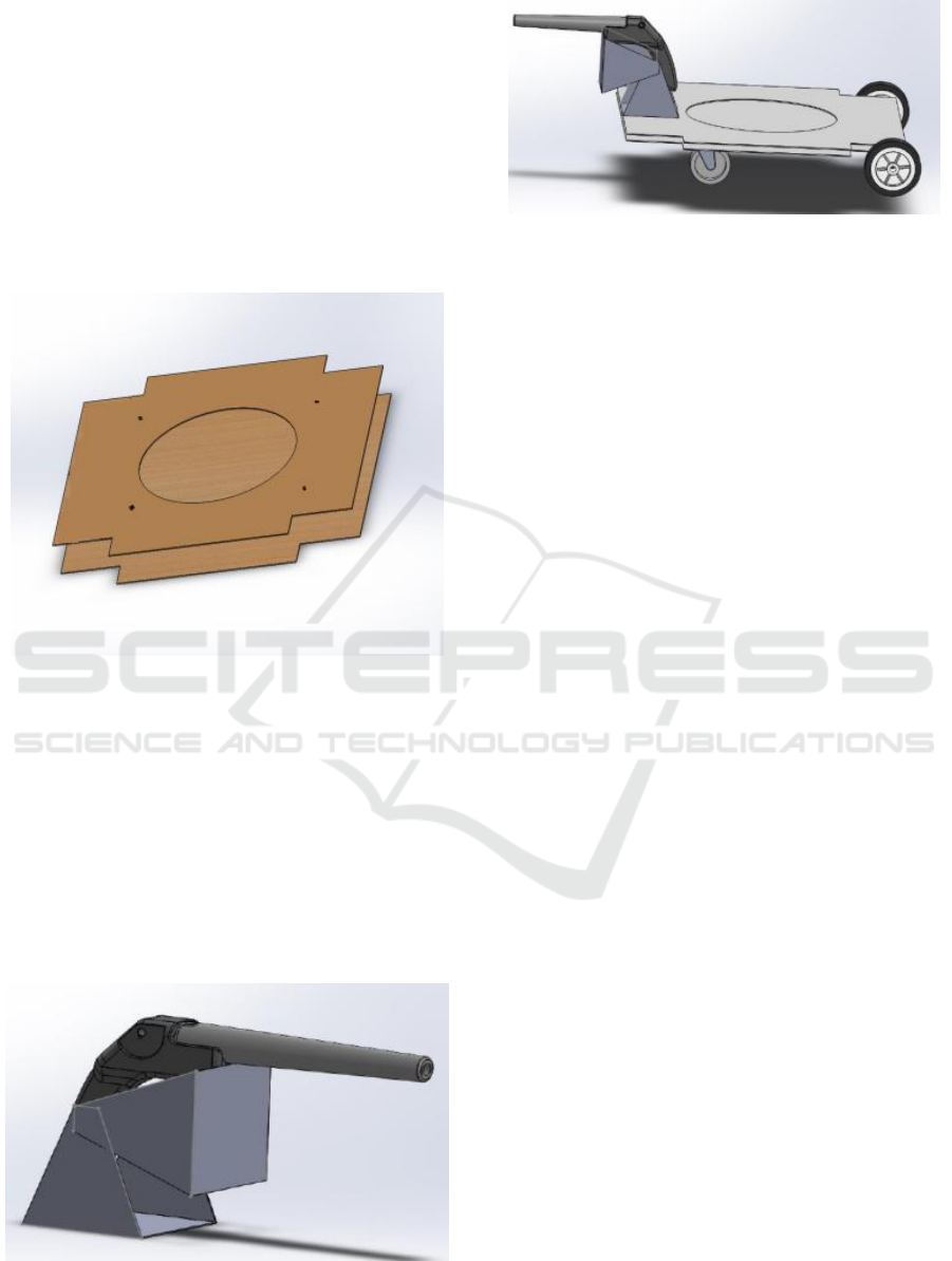
2.3 Base Platform Design
Figure 1: The assembly of the base platform.
Figure 1 shows the base of the firefighter robot. The
lower basement part has a dimension of 0.5m x 0.5m
and cut-outs of 0.1m x 0.05m. The cut-outs are made
to adjust the wheels insides of the robot. The upper
part has a dimension of 0.5m x 0.5m and cut-outs of
0.1m x 0.05m and a circular cut in the middle with a
diameter of 0.27m. The circular cut is made for the
purpose to set up a water tank. Figure 2 and 3 show
handles connected to the pistol as well as the base
connected to the handles and pistol.
Figure 2: The connection of handlers and pistol.
Figure 3: The base prototype.
2.4 Motor Selection
Motor’s key parameters are selected based on the
following calculations.
2.4.1 Required Speed
The speed of the robot is assumed to be 150 cm/s.
This assumption is made to find the RPM, which is
provided by the DC motor. The speed conversion
from cm/s to RPM is done in the following way:
V = r * ω (1)
Where V=velocity, r=radius of the tire, and
ω=angular velocity.
By substituting the values, ω=V/r, ω=(150cm/s)/5cm
ω=30rad/s , RPM=ω/2π (2)
RPM=(30rad/s)/2π*60
RPM=286.47rpm.
A minimum 286.47 RPM is needed to meet the
desired 150cm/s speed.
2.4.2 Required Torque
The required torque is the next property that needs to
be taken into account while selecting the DC motor.
The torque produced by the DC motor should be
sufficient to carry the total weight of the robot,
including the tank with the water. First, the force is
calculated as follows:
F = μ
r
* N (3)
Where, F=Force, μ
r
=Rotational friction co-efficient,
N=normal force. By substituting the values of the
rotational friction coefficient and normal force for an
assumed total weight of 27 kg, we get:
F = 0.015*(27kg*9.8m/s^2)
F = 3.969N
The equation of the torque:
T = D* F (4)
Development of a Network-based Autonomous Firefighting Robot
527
Where, D=distance (in this case D is r=radius of the
tire), T = 5cm* 3.969N, T = 19.845 cmN, The
selected DC motor needs to provide at least 286.47
rpm and a torque of 19.845 cmN.
3 ALGORITHM DEVELOPMENT
3.1 Obstacle Avoidance Algorithms
In the productive activity and life of the human
society, automation becomes increasingly essential.
In recent years, due to the significant decrease in
resources, global climate change, and population
growth, the role of automation is amplified, and it is
being expanded. To date, there are practically no
technical devices without automation elements -
from simple devices used in everyday life to
sophisticated industrial installations. Modern
humanity uses various devices, without which today
it is impossible to imagine a comfortable and safe
daily life.
For an autonomous vehicle, the ability to detect and
avoid obstacles in real time is a significant
embodiment and a fundamental guarantee of a
ground mobile robot for performing various tasks.
Consequently, there are some studies and solutions
to this problem, but most of these solutions require a
significant computational load and are complicated,
some even completely impossible. In general, there
are two types of avoidance technology: the first is
based on the global map, and the other is based on
sensors. In this work, two algorithms for preventing
obstacles in the implementation of low-cost control
structures based on microcontrollers and sensors,
namely, Bug1 and Bug2 are used.
Bug1 and Bug2 are motion planning algorithms that
are applied to mobile robots. For these algorithms,
sensors of the sonar range are used as sensing
elements. Mobile robots create new traffic planning
in those cases when they meet an unknown obstacle
while moving towards the goal. Bug's algorithms
create a path for moving the robot to the target in a
straight line if the path to the target is clear;
otherwise, the robot follows the obstacle border with
which it encounters (Lumelsky, 1990). These
algorithms are based on three assumptions about the
mobile robot: i) the robot is a point, ii) it has an ideal
localization, and iii) its sensors are accurate (James,
2007).
Bug1 is an algorithm by which a mobile robot
moves directly to the target unless it encounters an
obstacle. In the event of a collision with an obstacle,
the robot examines the outer lines of the obstacle
until it moves to the target is available
(Sankaranarayanan, 1990). As soon as it encounters
an obstacle, it bypasses the obstacle on one side, and
then determines the breakpoint, calculating the
distance between the current position and the
position of the target G while traveling around the
object. The remaining point is the nearest point
around the obstacle to the target. The robot then
determines the shortest path to this nearest point to
reach the breakpoint, and changes or maintains its
direction of the wall, following the shortest path to
return to the breakpoint. Then the robot goes to the
breakpoint and sends an obstacle in the direction G
along the new line. When it encounters the second
obstacle, the same procedure applies. This method is
inefficient but ensures that the mobile robot can
reach any possible goal point (Isabel Ribeiro, 2005).
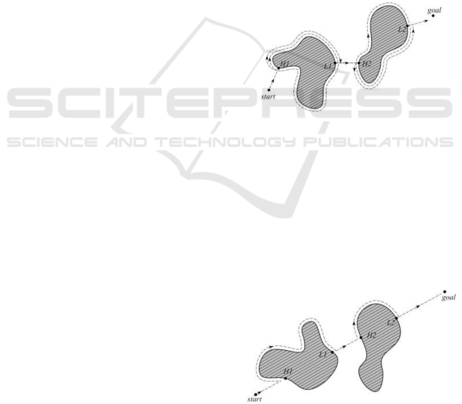
Figure 4 shows the Bug algorithm.
Figure 4: Illustration of the Bug algorithm.
According to the algorithm Bug2 as shown in Fig. 5,
the mobile robot follows a constant slope, calculated
initially between the positions S and G. The mobile
robot maintains its motion to G if the path on the
slope is not interrupted by the obstacle. If the robot
is in front of it, the robot follows the edges of the
obstacle, using its sonar sensors in a clockwise
direction until it finds its original inclination again.
This property leads to shorter paths than Bug1, but
in some cases the path may take longer than Bug1,
for example, searching for a labyrinth (Magid,
2004).
Figure 5: Illustration of the Bug2 algorithm.
ICINCO 2018 - 15th International Conference on Informatics in Control, Automation and Robotics
528
3.2 Movement
One of the primary requirements of the robot is the
movement. The following components provide the
movement of the robot:
(a) Wheels (2 of the conventional and 1 of
omnidirectional)
(b) DC motors (Two 12V DC motor)
(c) The connection between the wheels and DC
motor, as well as the connection of DC
motor and basement
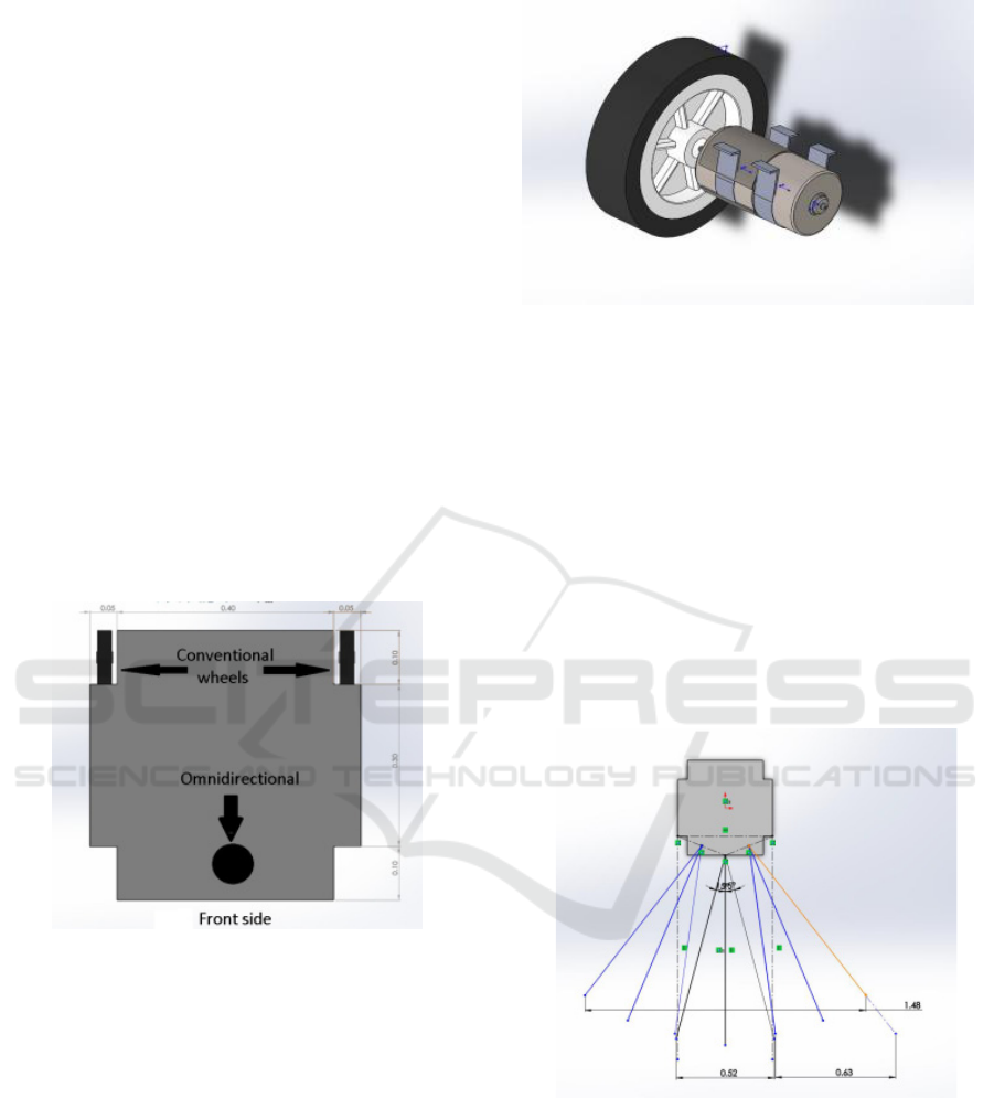
The following Fig. 6 illustrates the positions of
wheels in black color (2 conventional and 1
omnidirectional wheels). All the three wheels
provide the forward movement. The turning is
resulted by the stop of one back conventional wheel
and rotation of another. The omnidirectional wheel
provides the turning of the front side, as it can turn
in any direction and provide movement.
Figure 6: Positions of the wheels.
Two standard wheels are connected to a DC motor
by the metallic part by welding. The easiest and
reliable way of connection is welding. It leads to
simultaneous rotation of the wheels and the DC
motor’s rotational output. Each DC motor with the
conventional wheel is connected to the basement by
the two metal strips by screwing them into the lower
basement. The omnidirectional wheel is connected
to the lower basement by four screws. The following
Fig. 7 illustrates those as mentioned earlier (3)
connections.
Figure 7: The connection of (1) wheel, (2) DC motor and
metal two strips.
3.3 Navigation
The navigation is done in the following way:
(a) The gas sensor gives the location of the fire
(b) Wi-Fi module transfers the destination to
the robot
(c) The robot moves toward the fire by
avoiding the obstacles using ultrasonic
sensors. Figure 8 explains the location of
the ultrasonic sensors.
Figure 8: Ultrasonic sensors positioning.
3.4 Gas Sensor Network
The gas sensors are located in the room forming a
network to detect the smoke. The MQ-9 gas sensor
is used as a smoke detector. The amount of smoke is
directly proportional to the voltage output. The
supply voltage used in MQ-9 is 5V. Figure 9 shows
the gas sensor.
Development of a Network-based Autonomous Firefighting Robot
529
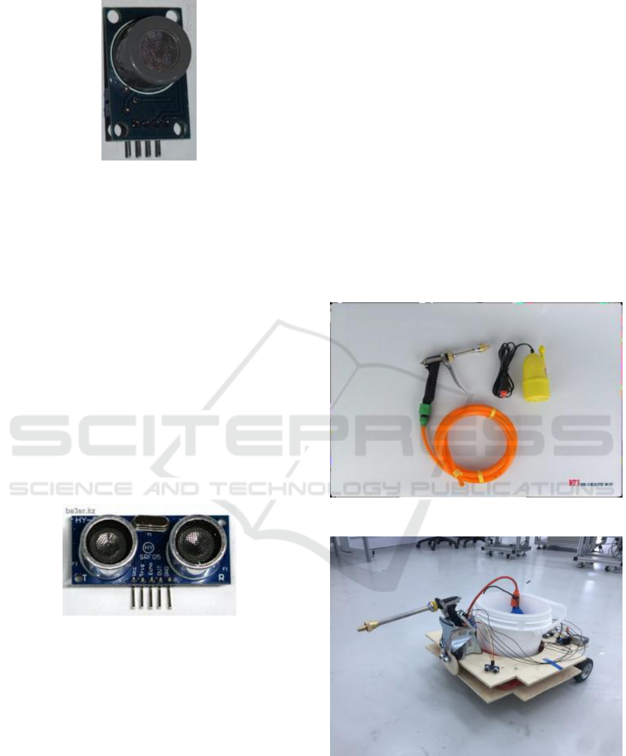
Figure 9: MQ-9 gas sensor.
As the network the room is divided into three
divisions, the following positioning is determined.
The network follows the following logic: when the
fire is detected at the location of the first sensor, the
destination is to be at first 150 x 100cm division of
the room; if the second sensor detects the smoke the
location is to be a second division, and the third for
the third division.
3.5 Obstacle Avoidance
When the robot moves toward the fire, detection of
the obstacles on the path
should be considered. In
the literature review, the logic of the obstacle
avoidance is suggested. As the way to avoid an
obstacle, the Ultrasonic sensor SRF05 is used. The
operating voltage of the sensor is 5V, and the
measurement angle is 30 degree.
Figure 10: SRF05 ultrasonic sensor.
Figure 10 shows the ultrasonic sensor used for this
research.
4 ASSEMBLY AND TEST
RESULTS
4.1 Fire Extinguishing
Water is used to extinguish the fire in this research.
The following components and technique are
incorporated into the system.
4.1.1 Gun and Water Pump
The last action for the robot is to extinguish fire
autonomously. The fire is extinguished by the
elimination of heat from the fuel, one of the
consistent of the fire triangle, by decreasing its
temperature by adding water into it. The water
stored in the water tank needs to be splashed into the
fire. For this purpose, the "minicar washer" is used.
The mini car washer system consists of the
following components.
(a) Pump
(b) Water Hose
(c) Water spray or gun
(d) Waterproof power wire
Figure 11: Mini car washer.
Figure 12: Isometric view of the prototype.
The total weight of the "minicar washer" system is
800g. The operating voltage is 12V. Figure 11
illustrates the "minicar washer". Figure 12
highlights the isometric view of the developed
prototype.
ICINCO 2018 - 15th International Conference on Informatics in Control, Automation and Robotics
530
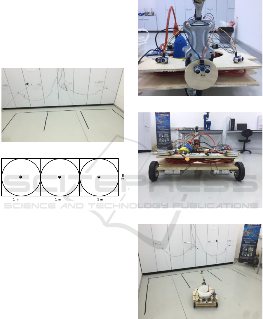
4.2 Network Room Set up
The network room is built in the laboratory by
dividing the 1m x 3m area into three 1m x1m
sections. Then, three gas sensors are placed above
each section and connected to an Arduino Uno. The
Wi-Fi module connected to this Arduino sends the
reading of each sensor to the robot. Figures 13 and
14 show the sensor networking.
Figure 13: Network room.
Figure 14: Gas sensor network.
4.3 Prototype Development and
Testing
Figures 15 and 16 show the front and rear view of
the robot. Figures 17 and 18 demonstrate the robot's
action during fire detection. The testing started with
the adjustment of the network room sensors. The
height for placement of each sensor and reading
range of each sensor configured simultaneously to
cover the sections. The robot’s navigation is done by
changing the Arduino code according to the path of
each sector. Then, by implementing Bayesian
Algorithm, the code is modified based on the
presence of an obstacle. The testing is done using a
candle as a source of the fire. The candle is placed in
each section and at different places with respect to
the sensor location.
Figure 15: Front view of the robot.
Figure 16: Rear view of the robot.
Figure 17: Robot in action.
Development of a Network-based Autonomous Firefighting Robot
531
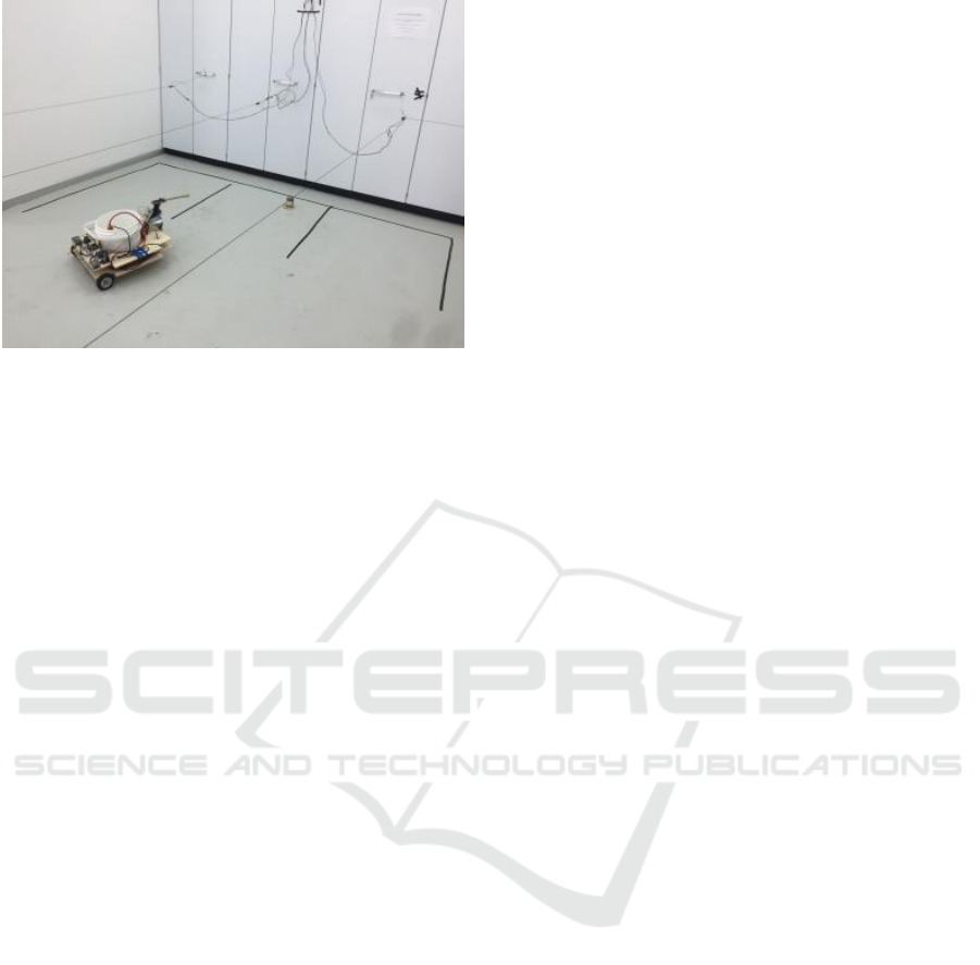
Figure 18: Side view of the robot during fire extinguish.
5 CONCLUSIONS
The focus of this research was the design, assembly,
and development of an intelligent firefighter robot
that would be able to extinguish a fire source
automatically. This work includes electrical,
mechanical and mechatronics systems. The sensor
network is needed for the fire detection. The
network of the gas sensors divide the room into three
sections and then detect the presence of fire within
the range. By the Wi-Fi communication between the
network and robot, the destination signal is
transmitted to the robot. By the implementation of
Bayesian Algorithm and using three ultrasonic
sensors to avoid an obstacle, the robot reaches the
fire. After reaching the fire, the robot starts the pump
and water splashes toward the fire, and as a result,
fire is extinguished. The test results were obtained
after several trials to reach the desired destination.
Overall, the primary objective of the research; such
as autonomous fire detection, robot navigation, and
autonomous fire extinguishing is met.
REFERENCES
Moore, R., Lopes, J., 1999. Paper templates. In
TEMPLATE’06, 1st International Conference on
Template Production. SCITEPRESS.
Smith, J., 1998. The book, The publishing company.
London, 2
nd
edition.
B. Li “Analysis of the Fire Fighting Robot”. 2011 “Child
strength first”. 2000 Product Safety and Testing
Group, Institute for Occupational Ergonomics and
Division of Manufacturing Engineering and
Operations Management, University of Nottingham,
University Park, Nottingham.
E. Krasnov and D. Bagaev, "Conceptual analysis of
firefighting robots' control systems," 2012 IV
International Conference "Problems of Cybernetics
and Informatics" (PCI), Baku, 2012, pp. 1-3. doi:
10.1109/ICPCI.2012.6486328
Evgeni Magid and Ehud Rivlin, CAUTIOUSBUG:
ACompetitive Algorithm for Sensory-Based Robot
Navigation, Proceedings of 2004 IEEE/RSJ
International Conference on Intelligent Robots and
Systems, Sendal - Japan, September 28 – October 2,
2004.
“Green seal report”, 2003. Green Seal Inc. url:
https://www.sandiego.gov/sites/default/files/legacy/en
vironmental-services/pdf/ep3/cgr_tires_rr.pdf.
James Ng and Thomas Bräunl, Performance Comparison
of Bug Navigation Algorithms, J Intell Robot Syst,
Springer Science 50:73–84 DOI 10.1007/s10846-007-
9157-6, 2007.
Jared Harwayne-Gidansky; Michael Sudano; “A Low-
Complexity Navigation Algorithm for a Scalable
Autonomous Firefighting Vehicle”, Research and
Development, the 5th Student Conference-SCOReD
2007, 11-12 December 2007.
M. Engin, "Embedded and real-time system design: A case
study firefighting robot," 2016 5th Mediterranean
Conference on Embedded Computing (MECO), Bar,
2016, pp. 18-21. doi: 10.1109/MECO.2016.7525712
Maria Isabel Ribeiro, Obstacle Avoidance, 2005.
M. K. Rangan, S. M. Rakesh, G. S. P. Sandeep and C. S.
Suttur, "A computer vision based approach for
detection of fire and direction control for enhanced
operation of firefighting robot," 2013 International
Conference on Control, Automation, Robotics and
Embedded Systems (CARE), Jabalpur, 2013, pp. 1-6.
doi: 10.1109/CARE.2013.6733740
S. C. Purbarani, Q. A'yunina MOA, G. Jati, M. A.
Ma'sum, H. A. Wisesa and W. Jatmiko,
"Implementation of grid mapped robot planning
algorithm in a continuous map for firefighting robot,"
2015 International Symposium on Micro-
NanoMechatronics and Human Science (MHS),
Nagoya, 2015, pp. 1-7. doi: 10.1109/MHS.2015.74
38292
Sankaranarayanan, A., Vidyasagar, M., A new path
planning algorithm for moving a point object amidst
unknown obstacles in a plane, Proc. of the IEEE Int.
Conf. Robot. Autom. 3, 1930–1936, 1990.
Scott Dearie; Kevin Fisher; Brian Rajala; Steven Wasson;
“Design and Construction of a Fully Autonomous Fire
Fighting Robot”, 2004 IEEE, Pages: 303-310.
Tawfiqur Rakib, M. A. Rashid Sarkar, "Design and
fabrication of an autonomous firefighting robot with
multisensor fire detection using PID controller", 2016
International Conference on Informatics, Electronics
and Vision (ICIEV), vol. 00, no. , pp. 909-914, 2016,
doi:10.1109/ICIEV.2016.7760132
“Ultrasonic ranging module: HC-SR04" URL:
http://www.micropik.com/PDF/HCSR04.pdf
V. Lumelsky and T. Skewis, Incorporating range sensing
in the robot navigation function, IEEE Transactions on
ICINCO 2018 - 15th International Conference on Informatics in Control, Automation and Robotics
532

Systems Man and Cybernetics, vol. 20, pp. 1058 –
1068, 1990.
Vecna Robotics Co.; “Battlefield Extraction-Assist Robot
(BEAR)”, Available: http://www.vecnarobotics.com/
robotics/product-services/bear-robot/ [Accessed: June
27, 2012]
Young-Duk Kim; Yoon-Gu Kim; Seung-Hyun Lee;Jeong-
Ho Kang; Jinung An; “Portable Fire Evacuation Guide
Robot System”, Intelligent Robots and Systems,
IEEE/RSJ International Conference, 11-15 October
2009. Pages: 2789-2794.
Development of a Network-based Autonomous Firefighting Robot
533
