
Geometrical Picture Integration in SEMI-CAVE Virtual Reality
Dariusz Sawicki
1
, Łukasz Izdebski
1
, Agnieszka Wolska
2
and Mariusz Wisełka
2
1
Warsaw University of Technology, Institute of Theory of Electrical Engineering,
Measurements and Information Systems, Warsaw, Poland
2
Central Institute for Labour Protection - National Research Institute (CIOP-PIB), Warsaw, Poland
Keywords: Image Stitching, Multimedia, Virtual Environment, Immersive VR, CAVE.
Abstract: Virtual reality (VR) is the most fascinating multimedia solution of recent years. Cave (Cave Automatic
Virtual Environment) is the most advanced example of VR installation. The aim of the work is to present an
image stitching problem in specific cave installation. The low-budget installation called SEMI-CAVE has
been built to study the impact of visual environment on human psychophysiology at the workplace. Six
projectors display images on four walls of a relatively large room. Correct stitching of images with perfect
geometry is the deciding factor in ensuring good immersion in VR under these conditions. We have
developed a special image stitching subsystem working in the SEMI-CAVE solution. The subsystem makes
it possible to easily combine individual images to ensure the correct geometry of the displayed content. In
addition, the implementation of the stitching subsystem was carried out at the shader level, which ensured
the fastest possible technical solution. The work presents subsystem assumptions, the method of
implementation and conducted tests.
1 INTRODUCTION
1.1 Motivation
Virtual reality (VR) is one of the most attractive
computer science solutions in recent years.
Attractive not only for players of computer game
and advertising specialists, but also scientists from
many fields. Cave (Cave Automatic Virtual
Environment) is the most spectacular example of VR
installation. Cave is a solution known for many
years, but due to the costs and many technical
problems this solution is relatively rarely used.
The realization discussed here – SEMI-CAVE –
is an example of cave implementation, projected and
developed in recent years in the Central Institute for
Labour Protection - National Research Institute
(CIOP-PIB). It is one of the laboratories which were
built as a part of Tech-Safe-Bio project (TECH-
SAFE-BIO, 2015). The research plans related to the
SEMI-CAVE laboratory include interdisciplinary
study on health and safety of employees. VR
solutions will allow the researchers to study the
impact of physical environment on workers. The
laboratory was initially launched in the end of 2015.
After the first work (technical issues and calibration)
we focused on experiments with acquiring images
for preparing VR environment. The impressions of
viewers have confirmed the correctness of the
project concept – i.e. sufficient immersion into VR.
The quality of the displayed image in CAVE
installations, is a key issue determining the
correctness of immersion into the virtual reality
created inside the installation. Most often, two
aspects of this problem are discussed (Slater, 2003):
• Immersion Into The Virtual Environment.
This concept defines how well VR represents
the real world. We can list the following
parameters: correctness of stitching and image
geometry, color rendering and perception,
viewing angle, image resolution, etc.;
• Presence. An aspect relating to the perception
of virtual reality by the user. In practice, not
measurable, connected with the person using
the installations at a given moment. This
parameter depends on: the content presented
for a long time inside the installation and the
emotional state. It depends on the quality of
the immersion in VR.
The first thing SEMI-CAVE users see when
entering a room is of course the whole image
displayed on all four walls. The impression of
100
Sawicki, D., Izdebski, Ł., Wolska, A. and Wisełka, M.
Geometrical Picture Integration in SEMI-CAVE Virtual Reality.
DOI: 10.5220/0006922701000107
In Proceedings of the 2nd International Conference on Computer-Human Interaction Research and Applications (CHIRA 2018), pages 100-107
ISBN: 978-989-758-328-5
Copyright © 2018 by SCITEPRESS – Science and Technology Publications, Lda. All rights reserved

immersion is determined at this point by the
correctness of building virtual reality through
component images (displayed on individual walls).
The decisive influence is the quality of stitching the
images and maintaining the correct image geometry
throughout the entire installation.
1.2 The Aim of the Article
The main aim of this paper is to present the stitching
subsystem in the SEMI-CAVE laboratory. The
geometrical integration of the images is one of the
most important task in preparation of the VR
installation environment. The proposed and tested
tools in SEMI-CAVE allow for correcting geometry
of the displayed images regardless of the projector
settings, always in the same, easy way.
2 THE STITCHING PROBLEM IN
CAVE INSTALATION
The most advanced VR installation called CAVE
(Cave Automated Virtual Environment) was
introduced in 1991 (Cruz-Neira et al., 1992). Using
this idea, several different solutions (CAVE2, wall
of monitors) were created later (Kim et al., 2013).
There are also many publications on the technical
aspects of CAVE solutions. The review works
deserve special attention (Zhou et al., 2009, Kim et
al., 2013, Muhanna, 2015).
The problem of stitching images in CAVE
installations involves two independent issues; both
are essential for our SEMI-CAVE laboratory:
• display stitching, and thus stitching to correct
the properties of display devices. Aspects such
as changes and inaccuracies in projectors
position, changes and differences in
displaying information are taken into account;
• panorama stitching, thus stitching the images
prepared for display in the CAVE installation.
In our laboratory also, the previously prepared
fragments must be combined into a single
unit, which enables proper display in the
entire SEMI-CAVE installation (on all walls).
2.1 Display Stitching
In an ideal (theoretical) situation, the projector
should be set so that the image it generates is
perfectly rectangular (undistorted). At the same
time, the image generated by this projector is
adjacent to the second image in such a way that
together they form a coherent image with an
unnoticeable boundary (connection). Of course, this
situation should occur for each pair of neighboring
images and the projectors that generate them. In
practice, it is not possible to achieve such an ideal
situation. Additionally, all parameters of device
(including optical) change (degrade) over time. The
only way to solve this problem is to use software
that corrects the image geometry. The software
should meet the following requirements:
• the possibility of geometry correction on the
principle of converting a quadrilateral into a
quadrilateral with the determination of
appropriate colors inside the resultant
quadrilateral by interpolation;
• software support implemented by means of a
simple, intuitive interface enabling easy shape
correction;
• the ability to visually check the correctness of
the proposed geometry correction by using (or
comparing with) a well-recognized pattern;
• two software operating modes: standard mode
(when displaying images) and editing mode,
during which geometry and color can be
corrected. It can be assumed that the editing
mode (correction) will be used relatively
rarely (once a month or less frequently);
• the correction mode of the software should,
above all, meet one basic condition. It must
work all the time while displaying each image
in the SEMI-CAVE installation. The
implementation of this task should be done in
the most effective way, using the computer
resources as little as possible.
2.2 Panorama Stitching
Currently, several algorithms are used to combine
images. The most popular methods based on feature
extraction are the SIFT and SURF algorithms. SIFT
(Scale Invariant Feature Transform) was proposed
by David Lowe in 1999 (Lowe, 2004). Initially, it
only included the problem of detecting the object,
that was sought in the photo. It was quickly
extended to stitch fragments (Evans, 2009) and to
the creation of panoramas (Hess, 2010). The SURF
(Speeded Up Robust Features) algorithm was
developed by Herbert Bay in 2006 (Bay et al.,
2008). It is used to detect and describe images based
on characteristic points (Evans, 2009, Hess, 2010).
The SURF algorithm is partially based on SIFT, but
is estimated to be several times faster in its standard
form than the SIFT. (Schweiger et al., 2009).
Geometrical Picture Integration in SEMI-CAVE Virtual Reality
101
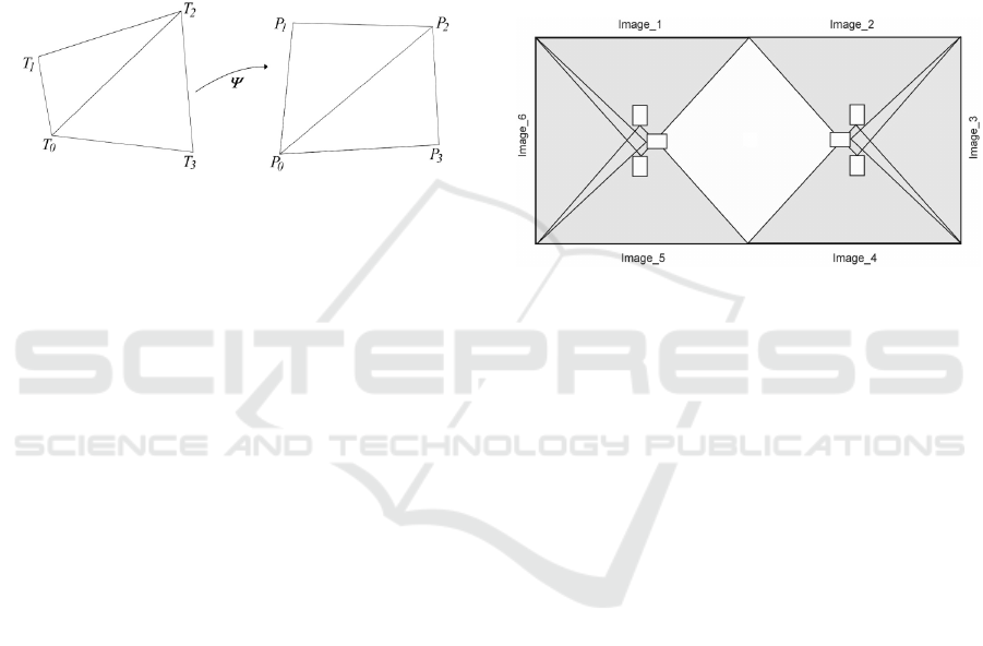
2.3 Quadrilateral into Quadrilateral
Transformation
Let points T
0
T
1
T
2
T
3
define quadrilateral. We are
looking for a transformation
Ψ
, which allows for
converting quadrilateral T
0
T
1
T
2
T
3
into quadrilateral
P
0
P
1
P
2
P
3
assuming the appropriateness of vertices.
Vertex T
i
is converted to vertex P
i
(Figure 1).
Conversion of a quadrilateral into a quadrilateral
is a geometric problem occurring in computer
graphics (Heckbert, 1989), image processing
(Bahram, 2002) and machine vision (Davies, 2005).
Figure 1: Transformation of the quadrilateral T
0
T
1
T
2
T
3
,
into the quadrilateral P
0
P
1
P
2
P
3
.
From a formal point of view, the transformation
of a quadrilateral into a quadrilateral is described by
homographic functions. This issue we can find in
many books related to image processing. The
simplest solution to this problem is to propose an
algorithm that uses a bilinear transformation.
Comparative analysis of various solutions of this
problem (Augustynowicz and Sawicki, 2016) shows
that it is difficult to indicate one universal algorithm
that would always carry out the task in the most
effective way. In specific conditions of a particular
application, it is worth considering the choice of
method. Nevertheless, in contemporary textbooks
(Hartley and Zisserman, 2004), the authors
recommend the DLT (Direct Linear Transformation)
algorithm (Abdel-Aziz and Karara, 1971) as the
best, practically universal solution. At the same
time, the DLT method is often cited in the literature
as the basic method for camera calibration in the
implementation of projection (Bardsley and Li,
2007, Dubrofsky, 2009).
3 SEMI-CAVE LABORATORY
Our installation (SEMI-CAVE) was dedicated to
study the impact of visual environment of the
workplace on human psychophysiology. The VR
installation and the virtual environment created in
this way should allow different working tasks to be
performed in a proper – specific environment. This
way the most important argument for choosing the
type of VR installation was the need for relatively
large room dimensions (VR space). We have
assumed that our virtual reality will be realized in a
room of dimensions: 8.6m x 4.3m with internal
projection. The minimum height of the image on the
wall is 2.8m and there are no images on the floor
and the ceiling. Such assumptions provide a
practical compromise between the simulations of the
working environment and the immersion benefits of
the virtual environment. Details of SEMI-CAVE
technical aspects were presented in (Sawicki et al.,
2017).
Figure 2: Arrangement of projectors that create six images
on the four walls.
We used six projectors for displaying images
(Figure 2). The main parameters are: brightness at
the level of 4000 lm ANSI, WUXGA resolution
(1920x1200), LCOS matrix, short throw optics with
Lens Shift and Keystone Correction in two
directions. These parameters make it possible to
obtain the expected shadow-free work area. The
projector has a built-in edge blending mechanism
which allows for basic stitching of the images. This
mechanism was used in the initial stage of the
installation. Initial, precise settings of projectors and
their hardware calibration ensured the correct
display and stitch of images. However, growing
mismatches have been observed over time. They
mainly result from vibrations and aging of the
supporting structure on which the projectors are
mounted. The problem turned out to be so important
that a few months after installation, there are
significant deviations between the images displayed
by individual projectors. This has an important
impact on the perception of images, and thus on
immersing into VR. Using the installation for a year
has shown that from time to time a correction of the
image stitching is required.
The standard operating scheme in our laboratory,
as in CAVE installations, allows for separating the
work of visualization algorithms into stages. On the
CHIRA 2018 - 2nd International Conference on Computer-Human Interaction Research and Applications
102
other hand, stitching the panorama in the SEMI-
CAVE installation is a rather rare task, although it is
necessary to combine real images with VR. It is
advisable to use known and available software
packages that allow for professional combination of
panoramas. A well-known analysis of the available
software (Comparison, 2018) has been published
and shows that Hugin program is currently one of
the most effective programs using feature extraction
methods (Hugin, 2018). This program uses the
PanoTools library (PanoTools, 2013) and is free
software distributed under the GNU GPL. An
additional advantage is that it is a software that
allows you to use a very wide set of different
projections – in particular: rectilinear, cylindrical,
spherical, and many others such as Mercator and
sinusoidal projections. This advantage was decisive
when choosing a solution – the proper projection in
CAVE installations has a decisive impact on the
immersion in the virtual world.
The camera calibration is compatible with the
calibration of projectors in the SEMI-CAVE
installation. Analyzing these known solutions, we
assumed that the DLT method is practically the best
solution to the problem of quadrilateral to
quadrilateral conversion for the SEMI-CAVE
installations. On the other hand, in our software the
algorithm of transformation will be used in two
situations: as a standard driver at the shader level
and as one of many applications for preparing
images of real objects to be used in SEMI-CAVE.
4 PROPOSED METHOD OF
CORRECTION FOR DISPLAY
STITCHING
In a small room of a typical CAVE installation (e.g.
2m x 2m x 2m), the VR space in relation to the real
space can be set practically arbitrarily. Even slight
deviations from the vertical should not be
noticeable. It is enough to match the quadrilateral
images between each other to stitch the images. In
SEMI-CAVE we deal with relatively large real
space and stitching operation is not so simple. The
basic problem is the need to define the reference
level of the VR space and match it to the selected
reference level of the real space. Theoretically, this
is the adjustment of the horizon, but in practice
"horizon" may mean a certain pre-arranged reference
level relevant (and important) to the given content of
the displayed image.
We assumed that the horizon line can be
independently defined for each image. This means
that it can be placed in any image height defined
independently (Figure 3). This approach gives the
possibility to define a common horizon line for all
six displayed areas in a convenient way. The horizon
understood in this way becomes the reference line
for the displayed information in the entire SEMI-
CAVE installation. It is worth emphasizing that in
such a situation it is possible to determine the
horizon line in the displayed areas, and then
compare this line (and its possible correction) with
the line pattern obtained from the laser level set in
the SEMI-CAVE laboratory. This allows eliminating
cases where the images are properly stitched
together, but the entire set of images is distorted. It
should be remembered that in a large spaces, VR
and real, it is very difficult to control distortion of
global geometry when the user corrects local
stitching. The horizon line as a reference level in the
whole space (laboratory) makes this correction task
much easier.
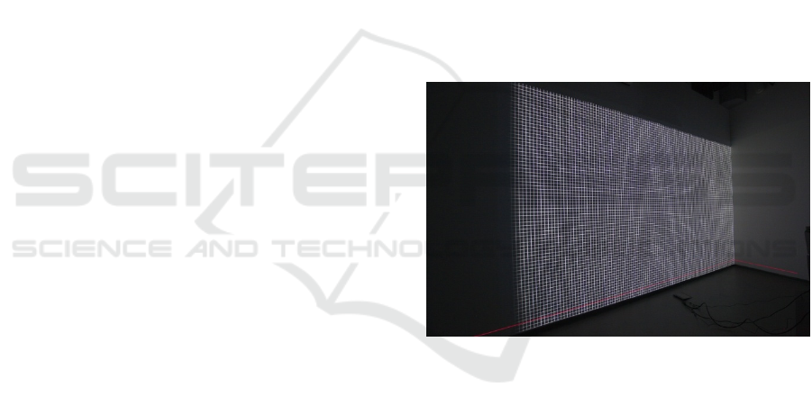
Figure 3: The position of the horizon line (red) arbitrary
defined at the bottom of images.
At the software level each of the six displayed
images functions independently and is displayed
independently. The configuration of each display is
also implemented independently. This approach to
display gives the possibility of individual geometry
settings, and thus gives the opportunity to correct
individual geometry for each of the projectors.
In the management of the display at the graphic
card level, we have adopted a normalized area
defining the geometry of the displayed image. It is
defined by the square {(-1,-1), (1,-1), (1,1), (-1,1)}.
After the first selection of the position of the horizon
line (y_hor selection), this area will be split into two
rectangles:
upper {(-1,y_hor), (1,y_hor), (1,1), (-1,1)}
lower {(-1,-1), (1,-1), (1,y_hor), (-1,y_hor)}.
Geometrical Picture Integration in SEMI-CAVE Virtual Reality
103
This allows for independent correction of both
rectangles. In this case, the operator can change the
position of six points. However, for the four vertices
of the normalized square it can change both x and y
coordinates, while for the two vertices associated
with the horizon line, only x coordinates (y
coordinates for this line were set at the horizon
definition level).
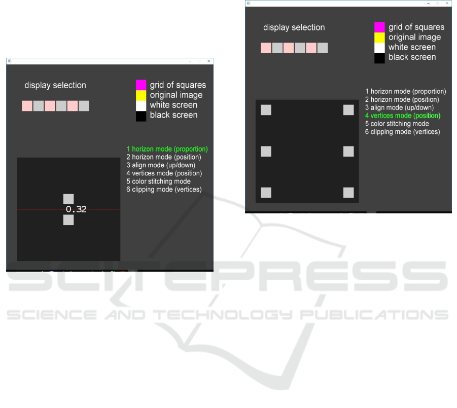
Figure 4: The GUI control panel of the software for
stitching display in editing mode. The step of changing
horizontal line position is selected (horizon mode). There
is a possibility to change position of the horizontal line
with the mouse or by entering a number that is the
proportion of the position relative to the height.
The software for stitching the display in the
editing mode gives the possibility to modify the
position of the respective elements in several steps.
In the first step, the operator selects the position of
the horizon using the GUI (Figure 4). Operator has
two possibilities of changing the position: by the
value of proportion (y position of the horizon line in
relation to the high of whole screen) or by the
position movement (by mouse). In the next step
there is possibility to align the VR horizon to real
horizon. It can be done by moving the whole image
up or down. In this step laser level is required as a
special additional equipment. In the third step
(vertices mode), the operator can intuitively
reposition the selected vertex using mouse
movements. (Figure 5). This approach gives very
wide possibilities to change the shape of the area to
ensure the adaptation to practically any conditions of
physical display by projectors. And it is
implemented in a simple and intuitive way. On the
other hand, the horizon line provides a reference
level that is not ensured by changing only the
position of vertices.
Figure 5: The GUI control panel of the software for
stitching display in editing mode. The step of changing
vertices position is selected (vertices mode). Position of
each can be changed independently with the mouse.
In addition, in the last step (clipping mode) the
operator can define the position of clipping lines in
order to clip the image to the standardized area. In
this mode only the position of the main vertices
(without horizon vertices) is taken into account
(Figure 6). Using this operation, the edges of
neighboring images can be independently aligned
(on a common wall or in the corners of the room).
The full algorithm for geometry correction in
SEMI-CAVE is as follows:
1. define the horizon level for the entire VR
space;
2. for each image: define the appropriate horizon
line (according to VR horizon level);
3. display the level of the (real) horizon by using
the laser level in the position closest to the
displayed horizon lines from the VR space;
4. for each image: adjust the image position to
match the horizon of the VR space to the
horizon of the real space;
5. for each image: adjust the position of the
vertices, according to stitch images in pairs
(pairs that are adjacent);
6. for each image: define clipping line for the
image, according to pairs of images (pairs that
are adjacent).
CHIRA 2018 - 2nd International Conference on Computer-Human Interaction Research and Applications
104
The image stitching subsystem has been
implemented at the shader level for the graphics card
processor. The software has been prepared in the
Visual Studio environment. For operating graphics
in the working mode, the Vulkan environment was
used (Sellers and Kessenich, 2016, Overvoorde,
2017). This is the most modern and probably the
most interesting technology currently used to
program advanced graphics. In the edit mode,
OpenGL environment was used. All implemented
operations within the appropriate shader have
hardware representations in the graphics card
processor. On the other hand, the division into
appropriate procedures in OpenGl and Vulkan was
designed to achieve the maximum performance of a
given processor. Moreover, since Vulkan is a
continuation of OpenGL and both libraries were
designed by the same company, most of the
procedures in them can easily be used
interchangeably. This has been effectively applied in
the SEMI-CAVE software.
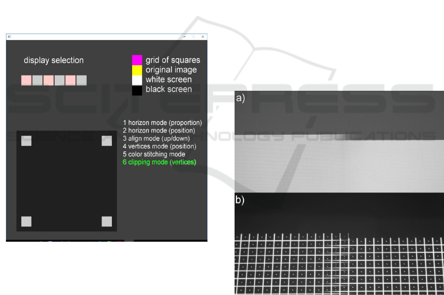
Figure 6: The GUI control panel of the software for
stitching display in editing mode. The clipping mode is
selected. Position of four vertices can be change
independently with the mouse.
5 VERIFICATION OF THE
SOLUTION
As part of the initial software tests, the correctness
of the implementation of individual operations was
checked and the work of algorithms for different
ranges of geometric correction was analyzed. Next,
we carried out the geometry correction in real
conditions in the SEMI-CAVE laboratory.
Verification of the proposed solution should be
related to the evaluation of the stitching correctness
and appropriate usability tests. However, in our
conditions it is very difficult. The images are either
properly stitched or not – it is difficult to analyze
intermediate states. Therefore, we have proposed a
simple metric that gives the answer whether the
correction is done well. The control images (grid
pattern) are designed in such a way that the
positioning of the corresponding control points can
be determined with accuracy to a single pixel. On
the one hand, such accuracy is sufficient to assess
the correctness of stitched images; on the other hand,
practically no better resolution is possible.
The first step in testing the developed software
for geometric correction was to stitch different
component images, including combining images in
the area of display on one (common) wall with two
projectors and in the corners of the room where the
adjacent images were displayed on adjacent walls.
We have developed control images using the black
and white grid of squares displayed in the positive or
negative version. They were chosen for the testing
and correcting the images geometry. The control
images facilitated the work greatly.
Figure 7: Area where two component images from
different projectors are displayed. a) The white rectangles
are displayed. b) The grid squares are displayed as control
images. Visible shift of images.
The final tests were done in SEMI-CAVE, in the
real arrangement of projectors, the positions of
which had not been adjusted. The aim of these tests
was to adjust and correct the real geometry. These
tests were carried out after about a year after the
Geometrical Picture Integration in SEMI-CAVE Virtual Reality
105
projectors’ hardware was set up (calibrated) of. Such
a long working time caused that the influence of
vibrations and aging of the mechanical elements of
the construction impacted the changes in the position
of projectors. Figure 7 shows a picture of an
example area in which two images from neighboring
projectors are displayed per wall. Visible, clear
shifting of the images reaches a size of
approximately 2 cm.
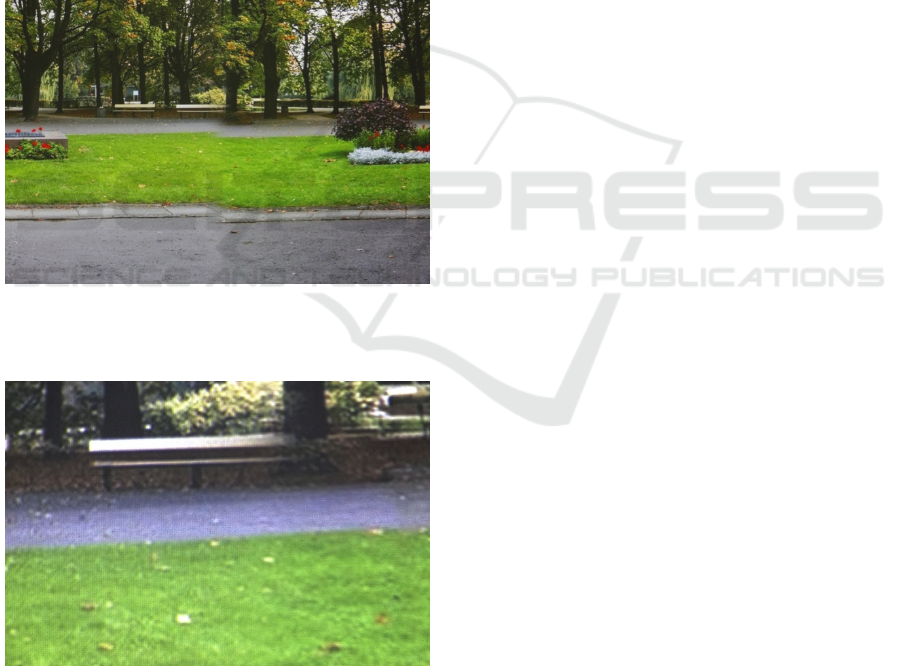
The consequences of decalibrating the position
of projectors are visible on the example images of
the Warsaw Saski Garden displayed in SEMI-
CAVE. Figure 8 shows a fragment with a clearly
visible divergence of component images. Figure 9
shows an enlarged fragment of images of the
Warsaw Saski Garden with clearly visible improved
display geometry. This is a fragment of the area
shown in Figure 8.
Figure 8: Area where two component images from
different projectors are displayed. The consequence of
shift of images presented in Figure 7.
Figure 9: An enlarged part from area shown in Figure 7
after correction. We can see the correct (uniform) border
between the lawn and the path.
It is worth noting that the possibility of
displaying images in the SEMI-CAVE installation is
possible only after closing the editing mode of the
stitching subsystem. This means that the correction
software sets the correction rules in the editing
mode, and the rules are apply at any time during the
software operation (in the display mode) and are
valid until the next change in the editing mode. Thus
the view, the fragment of which is shown in
Figure 9, can be displayed after the correction in
stitching mode and then after closing this mode.
Similar examples of corrections have been made
many times in the SEMI-CAVE installation for
different display areas. All experiments were
successful – just like the views presented in the
article. The correctness of the conducted tests
confirms the correctness of the introduced solution
concept, as well as the correctness of the software
implementation.
6 SUMMARY
In the article, we described the problems of stitching
images in a complex CAVE installation. We have
proposed the method to solve the problem and
developed the proper stitching subsystem. The
subsystem allows for combining individual images
to ensure the correct geometry in the displayed
space. In addition, our stitching subsystem gives full
control over the image creation process, which is an
important advantage of our own solution.
The relative large size of the real space in SEMI-
CAVE required a different, more advanced stitching
approach than used in typical CAVE applications. A
good solution facilitating the work was the horizon
line with the possibility of arbitrarily setting its
level. The experience and methods of stitching
images in the panorama were also very helpful.
The image stitching subsystem has been
implemented at the shader level and it is directly
executed by the graphics card processor. This
guarantees low CPU load of the main computer by
the whole task of geometric correction. The software
has been prepared using Vulkan – the best
contemporary technology for advanced graphics
programming.
We have conducted a series of tests in the real
conditions of the SEMI-CAVE laboratory. The tests
confirmed the correctness of the proposed solutions.
The interface for setting correction parameters in the
form of appropriately prepared GUI proved to be
very convenient in use. The best confirmation of the
stitching subsystem operation is the good impression
of immersion into VR after the geometry correction.
CHIRA 2018 - 2nd International Conference on Computer-Human Interaction Research and Applications
106

ACKNOWLEDGEMENTS
This paper has been based on the results of a
research task carried out within the scope of the
fourth stage of the National Programme
"Improvement of safety and working conditions"
partly supported in 2017–2019 within the scope of
research and development --- by the Ministry of
Science and Higher Education / National Centre for
Research and Development. The Central Institute for
Labour Protection -- National Research Institute is
the Programme's main coordinator.
REFERENCES
Abdel-Aziz, Y.I., Karara, H.M., 1971. Direct linear
transformation from comparator coordinates into
object space coordinates in close-range
photogrammetry. In: Proc. of the Symposium on
Close-Range Photogrammetry. American Society of
Photogrammetry, pp. 1-18.
Augustynowicz, M., Sawicki, D. 2016. Reconstruction of
the relative coordinates of image using projective
geometry. Przeglad Elektrotechniczny. 92 (1), 208-
211. doi:10.15199/48.2016.01.49.
Bahram, J. (ed.), 2002. Image Recognition and
Classification: Algorithms, Systems and Applications.
CRC Press.
Bardsley, D., Li, B., 2007. 3D Reconstruction Using the
Direct Linear Transform with a Gabor Wavelet Based
Correspondence Measure. Technical Report 2007.
http://bardsley.org.uk/wp-content/uploads/2007/02/3d-
reconstruction-using-the-direct-linear-transform.pdf,
last accessed 2017/11/09.
Bay, H., Ess, A., Tuytelaars, T., Van Gool. L., 2008.
SURF: Speeded Up Robust Features. Computer Vision
and Image Understanding (CVIU). 110 (3), 346-359.
Comparison of photo stitching software, 2018.
https://en.wikipedia.org/wiki/Comparison_of_photo_st
itching_software, last accessed 2018/04/19.
Cruz-Neira, C., Sandin, D.J., DeFanti, T.A., Kenyon, R.,
Hart, J.C., 1992. The CAVE: Audio Visual Experience
Automatic Virtual Environment. Communications of
the ACM. 35 (6), 64-72. doi: 10.1145/129888.129892.
Davies, E.R., 2005. Machine Vision. Theory, Algorithms,
Practicalities. Morgan Kaufmann.
Dubrofsky, E., 2009. Homography Estimation. Master's
Essay. The University of British Columbia.
Evans, Ch. 2009. Notes on the OpenSURF Library.
http://www.cs.bris.ac.uk/publications/papers/2000970.
pdf, last accessed 2017/11/09.
Hartley, R., Zisserman A., 2004. Multiple View Geometry
in Computer Vision (sec ed). Cambridge University
Press.
Heckbert, P.S., 1989. Fundamentals of Texture Mapping
and Image Warping. Master’s Thesis. University of
California, Berkeley.
Hess, R., 2010. An Open-Source SIFT Library. In: Proc.of
the 18th ACM International Conference on
Multimedia. MM'10. October 2010, Firenze Italy, pp.
1493-1496.
Hugin - Panorama photo stitcher, 2018. http://hugin.
sourceforge.net/, last accessed 2018/05/01.
Kim, M.J., Wang, X., Love, P.E.D., Li, H., Kang, S.C.,
2013. Virtual reality for the built environment: a
critical review of recent advances. Journal of
Information Technology in Construction. 18, 279-305.
available from: http://www.itcon.org/2013/14.
Lowe, D.G., 2004. Distinctive Image Features from Scale-
Invariant Keypoints. International Journal of
Computer Vision. November 2004, 60 (2), 91-110.
Muhanna, M.A., 2015. Virtual reality and the CAVE:
Taxonomy, interaction challenges and research
directions. Journal of King Saud University –
Computer and Information Sciences. 27 (3), 344-361.
doi: 10.1016/j.jksuci.2014.03.023.
Overvoorde, A., 2017.
Vulkan Tutorial. https://vulkan-
tutorial.com/Introduction , last accessed 2018/04/09.
PanoTools Panorama Tools, 2013. http://panotools.
sourceforge.net/, last accessed 2017/11/09.
Sawicki, D., Wolska, A., Wisełka, M., Żukowski, J.,
Sołtan, M., Związek, W., 2017. Semi-Cave as an
example of multimedia dedicated to study the impact
of audiovisual environment on human
psychophysiology. In: Proc. of the International
Conference on Computer-Human Interaction
Research and Applications (CHIRA 2017). Funchal,
Madeira, Portugal. October 31 – November 2, 2017,
pp. 103-110. doi: 10.5220/0006497601030110.
Schweiger, F., Zeisl, B., Georgel, P., Schroth, G.,
Steinbach, E., Navab, N. 2009. Maximum Detector
Response Markers for SIFT and SURF. In: Modeling
and Visualization Workshop (VMV). Braunschweig,
Germany. November 2009.
Sellers, G., Kessenich, J., 2006. Vulkan Programming
Guide: The Official Guide to Learning Vulkan.
Addison-Wesley.
Slater, M., 2003. A Note on Presence Terminology,
http://www.cs.ucl.ac.uk/research/vr/Projects/Presencia
/ConsortiumPublications/ucl_cs_papers/presence-term
inology.htmmelslaterJan27200391557.htm, last acces-
sed 2017/11/09.
TECH-SAFE-BIO - The Centre for Research and
Development on Work Processes and Safety
Engineering, 2015. http://www.ciop.pl/CIOPPortal
WAR/appmanager/ciop/en?_nfpb=true&_pageLabel=
P33200114301448620711504, last accessed
2017/05/13.
Zhou, N.N., Deng, Y.L., 2009. Virtual reality: A state-of-
the-art survey. International Journal of Automation
and Computing. 6 (4), 319-325. doi: 10.1007/s11633-
009-0319-9.
Geometrical Picture Integration in SEMI-CAVE Virtual Reality
107
