
Design of a Novel Six-Axis Force/Torque Sensor based on Optical
Fibre Sensing for Robotic Applications
Jun Huang
1
, Chu Yan Wong
1
, Duc Truong Pham
1
, Yongjing Wang
1
, Chunqian Ji
1
, Shizhong Su
1
,
Wenjun Xu
2
, Quan Liu
2
and Zude Zhou
2
1
Department of Mechanical Engineering, School of Engineering, University of Birmingham, Birmingham, B15 2TT, U.K.
2
School of Information Engineering, Wuhan University of Technology, Wuhan, 430070, China
Keywords: Six-Axis Force/Torque Sensor, Robotic Application, Optical Fibre Sensing, Fibre Bragg Grating (FBG).
Abstract: Force and torque information is critical to enabling intelligent control of a robot in complex robotic
applications. This paper presents a novel six-axis force/torque sensor based on optical fibre sensing for robotic
applications in extreme environments with intense electromagnetic interference as well as explosive and
inflammable materials. The designed sensor employs an elastic sensing element composed of 4 compliant
beams and 4 elastic cross beams to convert the measured forces and torques to the strain on the surfaces of
elastic cross beams, which is detected by 16 Fibre Bragg Gratings (FBGs). The strain is calculated by
theoretical analysis using Timoshenko beam theory and validated by Finite Element Analysis (FEA). Working
matrix of the sensor is constructed, which is associated with the relationships between the measured forces
and torques and the wavelength shifts of FBGs. The sensitive coefficients obtained by theoretical analysis and
FEA simulation are in good agreement, which indicates that the analytical method is accurate. The proposed
six-axis force/torque sensor with low cost and high reliability has great potential in robotic applications in
harsh industrial environments.
1 INTRODUCTION
Six-axis force/torque sensors enable robots to obtain
force and torque feedback information and achieve
intelligent control, which is increasingly important in
robotic applications such as robotic
assembly/disassembly, deburring, polishing,
grinding, cooperation with humans, and so on (Kim
et al., 2017, Yao et al., 2016a, Sun et al., 2016). For
instance, a six-axis force/torque sensor was adopted
to realize flexible force control on an industrial robot
for spacecraft assembly (Yuee et al., 2017). Six-axis
force/torque sensor was employed in humanoid robot
foot for stable control (Wu et al., 2013). A capacitive-
type six-axis force/torque sensor was developed for
force control of industrial robots (Li et al., 2017). Six-
axis force/torque sensor (or six-axis force/moment
transducer) can simultaneously detect all six
components including three orthogonal forces (Fx, Fy
and Fz) and three orthogonal torques (Tx, Ty and Tz)
at a certain point on a plate (Kim et al., 2017).
Table 1: Six-axis force/torque sensors.
Principle Work
Strain gauge
(Wang et al., 2017), (Okumura et al.,
2017), (Yao et al., 2016b), (Sun et al.,
2016), (Ballo et al., 2016), (Kang et al.,
2014), (Feng et al., 2015), (Wu and Cai,
2013), (Ma et al., 2013), (Ballo et al.,
2013)
Piezoelectric
(Li et al., 2017), (Becker et al., 2017),
(Liu et al., 2014), (Estevez et al., 2012),
(Liu et al., 2011), (Li et al., 2009),
Capacitor
(Kim et al., 2018), (Lee et al., 2016),
(Brookhuis et al., 2014), (Bar-Cohen et
al., 2013),
Others
(Guggenheim et al., 2017), (Zhao et al.,
2016), (Kim and Lee, 2016), (Müller et
al., 2009), (Beyeler et al., 2009)
Currently, most developed and commercial six-
axis force/torque sensors have used strain gauge,
Huang, J., Wong, C., Pham, D., Wang, Y., Ji, C., Su, S., Xu, W., Liu, Q. and Zhou, Z.
Design of a Novel Six-Axis Force/Torque Sensor based on Optical Fibre Sensing for Robotic Applications.
DOI: 10.5220/0006911705170524
In Proceedings of the 15th International Conference on Informatics in Control, Automation and Robotics (ICINCO 2018) - Volume 1, pages 517-524
ISBN: 978-989-758-321-6
Copyright © 2018 by SCITEPRESS – Science and Technology Publications, Lda. All rights reserved
517

piezoelectric and capacitor, as shown in Table 1.
However, these electrical-type sensors are typically
expensive and could not work well in harsh
environments with intense electromagnetic
interference as well as explosive and inflammable
materials (Guggenheim et al., 2017). Therefore, new
six-axis force/torque sensors with low cost and high
reliability are highly desirable to enable robots to
work in extreme environments.
Compared with traditional electrical sensing
technology, Fibre Bragg Grating (FBG) as one kind
of typical optical fibre sensing technologies has
unique advantages such as immunity to
electromagnetic interference, resistance to corrosion
and chemicals, multi-parameter measurement,
multiplexing capability, remote signal transmission,
and so on (Jiang et al., 2018). In recent years, FBG
sensors have been widely studied and applied in
various fields (Diaz et al., 2018, Wei et al., 2017, Tian
et al., 2017, Mieloszyk and Ostachowicz, 2017).
There has not been much reported research into six-
axis force/torque sensors using FBGs. A 6-DoF
force/moment sensor using FBGs for robotic surgery
was developed (Kim and Lee, 2016).
This paper presents a novel six-axis force/torque
sensor based on optical fibre sensing for robotic
applications in extreme environments. The proposed
sensor uses an elastic sensing element with 4
compliant beams and 4 elastic cross beams to convert
the measured forces and torques to strain on the
surfaces of elastic cross beams. 16 FBGs are
employed to detect the strain and construct the
relationships between their wavelengths and the
measured six-axis forces and torques. The paper is
organised as follows. Section 2 focuses on FBG
sensing technology and the measurement principle of
the proposed sensor is outlined in Section 3. FEA
simulation analysis of the strain on the surfaces of
elastic cross beams is described in Section 4. Section
5 reports and discusses the analysis results. Finally,
the conclusions are presented in Section 6.
2 FBG SENSING TECHNOLOGY
FBG adopts light as sensing signal and the mean of
data transmission. Bare FBG is sensitive to strain
and temperature. Combining elastic sensing
elements with different functions to sense and
convert the measured physical quantities to
quantities (like strain) that could be detected by
FBGs enables FBGs to measure different physical
parameters.
2.1 Fibre Bragg Grating
FBG is written by exposing the core of an optical fibre
to intense UV light (Wang et al., 2016). The central
wavelength (λ
B
) of the reflected light by FBG in the
core of optical fibre can be defined as (Koyama et al.,
2017):
=2
Λ (1)
where n
eff
is the effective refractive index of fibre core
material, and Λ is the Bragg grating period. The
wavelength shift of FBG (Δλ
B
) is simultaneously
modulated by strain and temperature, which affect n
eff
and Λ.
The Bragg wavelength shift (Δλ) of FBG is
sensitive to strain and temperature changes, which
could be found in the following equation.
=
(
1−
)
Δε+(α
+ξ)ΔT (2)
where λ is the initial central wavelength of FBG. p
e
,
α
f
and ξ are the effective photo-elastic coefficient, the
thermal expansion coefficient and the thermal-optic
coefficient of fused silica fibre, respectively.
2.2 Temperature Compensation
Method
To handle the problem of strain and temperature
cross-sensitivity, temperature compensation is
essential for FBGs to measure strain accurately (Chen
et al., 2017). In this paper, the difference of
wavelength shifts of two FBGs (FBG1 and FBG2) as
a pair are used as the sensing signals of the measured
forces and torques, which are employed to measure
positive (or tensile) strain and negative (or
compressive) strain on the opposite surfaces of an
elastic cross beam. According to equation (2), the
wavelength shifts of FBG1 and FBG2 could be
obtained:
Δλ
=
(
1−
)
Δε
+
(
α
+ξ
)
ΔT
(3)
Δλ
=
(
1−
)
Δε
+
(α
+ξ)ΔT
(4)
The initial wavelengths λ
FBG1
and λ
FBG2
could be
replaced by an equivalence value (λ) due to that the
initial wavelengths are much larger than the
wavelength shifts. Assuming the two FBGs undergo
ICINCO 2018 - 15th International Conference on Informatics in Control, Automation and Robotics
518
the same temperature variation ( ∆
=∆
), the
difference between the two wavelength shifts could
be estimated by equation (3) equation (4) (Huang et
al., 2013):
Δλ
−Δλ
=λ(1−
)(Δε
−Δε
) (5)
For an FBG with a central wavelength of 1550
nm, its typical strain sensitivity is approximately 1.2
pm/micro-strain. The equation (5) can be adapted as:
Δ
−Δ
0.833
(
∆
−∆
)
(6)
As shown in equation (6), the wavelength shift
difference of the two FBGs is employed as sensing
signal of the measured forces or torques, which can
cope with the temperature cross-sensitivity problem
and increase force/torque sensitivity.
3 SENSOR STRUCTURE AND
PRINCIPLE
3.1 Sensor Structure
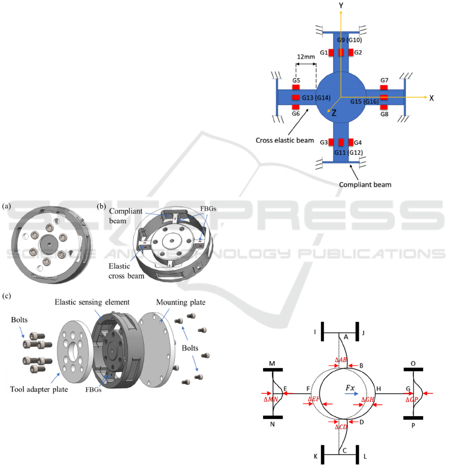
Figure 1: Structure of the six-axis force/torque sensor (a)
sensor assembly, (b) elastic sensing element, (c) explored
view.
Figure 1(a) illustrates the assembly of designed six-
axis force/torque sensor. As shown in Figure 1(b), the
sensor consists of 16 FBGs, an elastic sensing
element, a tool adapter plate, a mounting plate and 14
bolts. Figure 1(b) depicts the FBGs and the elastic
sensing element composed of 4 compliant beams and
4 elastic cross beams.
3.2 Measurement Principle
The elastic sensing element converts the measured
force/torque into the strain on the surfaces of elastic
cross beams which could be detected by FBGs. As
shown in Figure 2, 16 FBGs are mounted on the
surfaces of elastic cross beams along their length
direction, which are coded from G1 to G16.
Figure 2: Arrangement of FBGs on elastic cross beams.
The elastic inner hub is assumed to be ideal. The
strain calculation can be simplified into four
parameters which are
(or
),
,
(or
) and
due to the symmetrical structure of elastic sensing
element. The method of strain calculation is based on
Timoshenko beam theory (Wang et al., 2017).
3.2.1 Strain Analysis under Force Fx (Fy)
Figure 3: Deformation of the elastic sensing element under
force Fx (Wang et al., 2017).
Figure 3 shows the deformation of the elastic
sensing element under force
. The cross elastic
Design of a Novel Six-Axis Force/Torque Sensor based on Optical Fibre Sensing for Robotic Applications
519
beams of AB and CD and the compliant beams of
MN and OP are subjected to bending deformations.
The deformations of elastic beams (EF and GH) and
compliant beams (IJ and KL) are small, which can
be ignored. Due to the symmetrical structure, the
deformation of elastic cross beam AB is equal to that
of beam CD. Taking beam AB as an example, the
strain on its surface under force
can be obtained
(Wang et al., 2017):
=
(
)
()
(7)
=
+
,=
+
(8)
where x is the distance between any cross-section on
beam AB and the inner round hub; E is the Young’s
modulus; G is the shear modulus; I is the second area
moment and A is cross-sectional area. k is the
shearing-shape coefficient of beam section. l
e
, w
e
and
h
e
are the length, width and height of elastic cross
beams, respectively. l
c
, w
c
and h
c
are the length, width
and height of compliant beams, respectively.
=
(
)/12
is the second area moment of cross-
section, and
=
is the cross-section area of
beam.
=(
)/12
is the second area moment of
cross-section, and
=
is the cross-section
area of beam.
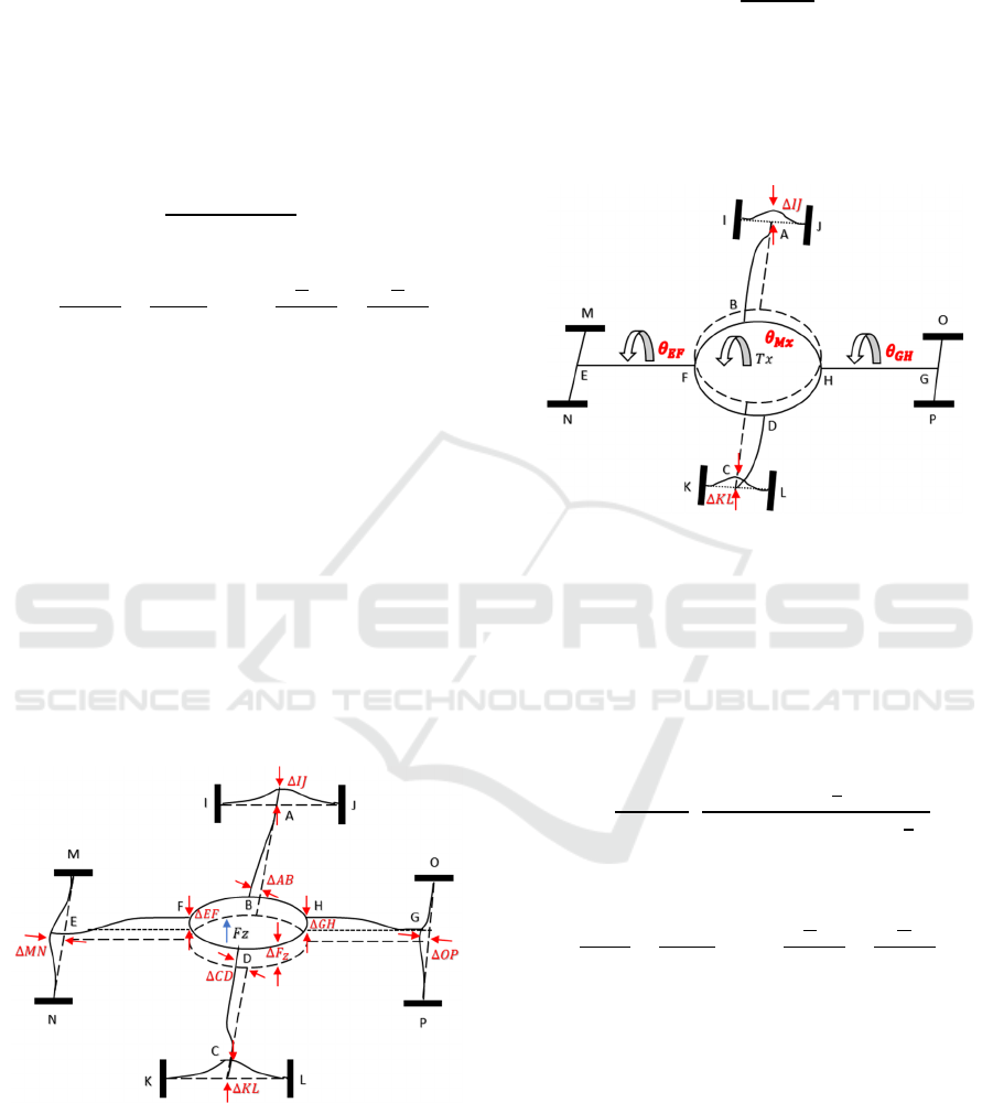
3.2.2 Strain Analysis under Force Fz
Figure 4: Deformation of the elastic sensing element under
force Fz (Wang et al., 2017).
Figure 4 illustrates the deformation of the elastic
sensing element under force
. Elastic cross beams
are in bending deformations, which could be treated
as cantilever beams. The strain on elastic cross
beams can be calculated by (Wang et al., 2017):
=
(
)
(9)
where
=(
)/12
is the second area moment of
cross-section.
3.2.3 Strain Analysis under Torque Tx (Ty)
Figure 5: Deformation of the elastic sensing element under
torque Tx (Wang et al., 2017).
Figure 5 depicts the deformation of the elastic sensing
element under torque
. The beams of AB and CD
perform bending deformations. The beams of EF and
GH produce torsion deformations. The strain on
elastic cross beams can be calculated by (Wang et al.,
2017):
=
(
)
(
)
(
)
(
)
(10)
=
+
,=
+
(11)
where
=0.141
and
is the diameter of the
inner hub.
=(
)/12
is the second area
moment of cross-section, and
=
is the cross-
section area of beam.
=(
)/12
is the second
area moment of cross-section, and
=
is the
cross-section area of beam.
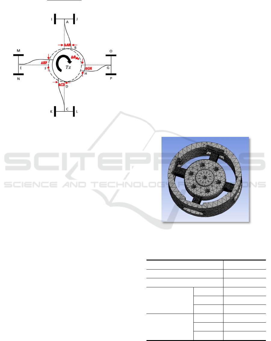
3.2.4 Strain Analysis under Torque Tz
The deformation of the elastic sensing element under
torque
is shown in Figure 6. Four elastic cross
beams have the same deformation. The strain on the
ICINCO 2018 - 15th International Conference on Informatics in Control, Automation and Robotics
520
surface of elastic cross beams can be calculated by
(Wang et al., 2017):
=
(
)
(
)
(12)
Figure 6: Deformation of the elastic sensing element under
torque Tz (Wang et al., 2017).
3.2.5 Working Matrix
According to the equation (7), (9), (10) and (12), the
relationships between the strain on elastic cross
beams and the applied forces and torques are linear.
The strain on the opposite surfaces of an elastic cross
beam is positive and negative, respectively. The strain
at 16 FBG positions can be divided into 8 pairs. The
strain matrix of the sensor could be described as:
ε
−ε
ε
−ε
ε
−ε
ε
−ε
ε
−ε
ε
−ε
ε
−ε
ε
−ε
=
F
F
F
T
T
T
(13)
Where [k] is an 8 x 6 strain coefficient matrix. As the
matrix [k] is not square, the Moore-Penrose pseudo-
inverse matrix is calculated to be:
k
=(k
k)
k (14)
Combining equation (6) and (11), the working matrix
of the sensor could be obtained, as shown in equation
(15). The differences of the wavelength shifts of
FBGs in 8 pairs are employed as sensing signals to
measure forces and torques. If the wavelength shifts
of FBGs were acquired, the measured six-axis forces
and torque could be calculated.
=0.833
Δλ
−Δλ
Δλ
−Δλ
Δλ
−Δλ
Δλ
−Δλ
Δλ
−Δλ
Δλ
−Δλ
Δλ
−Δλ
Δλ
−Δλ
(15)
4 FEA SIMULATION ANALYSIS
To validate the proposed calculation method, the
strain distributions on elastic cross beams are
analysed by using FEA simulation with ANSYS.
Figure 7 shows the 3D CAD model of the elastic
sensing element with meshes. High-density meshes
are selected for the elastic cross beams.
Figure 7: 3D CAD model of the elastic sensing element
with meshes.
Table 2: Dimensions of the elastic sensing element.
Component Value (mm)
Outer body diameter 155
Inner hub diameter (d) 88
Elastic cross beam
length (l
e
) 25.07
width (w
e
) 9
height (h
e
) 17.3
Compliant beam
length (l
c
) 44
width (w
c
) 17.3
height (h
c
) 2.5
Design of a Novel Six-Axis Force/Torque Sensor based on Optical Fibre Sensing for Robotic Applications
521
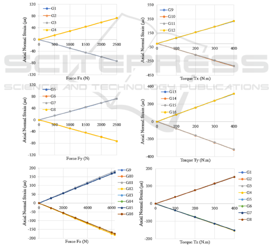
Table 2 summarizes the dimensions of the elastic
sensing element. The material of the elastic sensing
element is hardened stainless steel 304. The
mechanical properties are Young’s modulus of 193
GPa, Poisson’s ratio of 0.31, tensile strength of 520
MPa, the yield strength of 250 MPa and shear
modulus of 73.7 GPa.
5 RESULTS AND DISCUSSION
Figure 8 illustrates the linear relationships between
the strain on the positions of 16 FBGs and the forces
and torques using FEA simulations. As shown in
Figure 8, 4 FBGs (which could be divided into two
pairs on opposite surface of the same elastic cross
beam) could be used to measure Fx (G1, G2, G3 and
G4), Fy (G5, G6, G7 and G8), Tx (G9, G10, G11 and
G12) and Ty (G13, G14, G15 and G16), respectively.
The FBGs from G9 to G16 could be used to measure
force Fz and the FBGs from G1 to G8 could be used
to detect torque Tz.
Equation (16) and (17) show the strain coefficient
matrixes obtained by FEA simulation and theoretical
analysis, respectively.
k
=
−0.059 0 0 0 0 0.762
−0.059 0 0 0 0 0.762
0 −0.058 0 0 0 0.762
0 −0.058 0 0 0 0.762
0 0 0.056 1.603 0 0
0 0 0.056 1.603 0 0
0 0 0.058 0 1.590 0
0 0 0.058 0 1.590 0
(16)
Figure 8: Relationships between strain on positions of 16 FBGs and the applied forces and torques.
ICINCO 2018 - 15th International Conference on Informatics in Control, Automation and Robotics
522

=
−0.058 0 0 0 0 0.826
−0.058 0 0 0 0 0.826
0 −0.058 0 0 0 0.826
0 −0.058 0 0 0 0.826
0 0 0.057 1.669 0 0
0 0 0.057 1.669 0 0
0 0 0.057 0 1.669 0
0 0 0.057 0 1.669 0
(17)
Table 3 lists the calculation errors between the
results obtained by FEA simulation and theoretical
analysis. The maximum measurement error of the
strain coefficients is 7.7 %. The analysis results show
that calculated results by theoretical analysis and FEA
simulation are in good agreement.
Table 3: Errors between the strain coefficients obtained by
FEA simulation and theoretical analysis.
FEA simulation Theoretical analysis Errors
-0.059 -0.058 1.7%
0.762 0.826 7.7%
-0.058 -0.058 0
0.056 0.057 1.8%
1.603 1.669 3.9%
1.590 1.669 4.7%
Preliminary research shows that the proposed
method for the working matrix calculation of the six-
axis force/torque sensor is feasible. The sensor
prototypes are being manufactured and experimental
studies will be carried out to investigate their
performance.
6 CONCLUSIONS
Reliable force/torque sensation plays a significant
role in state-of-the-art robot controls. This paper has
presented a novel six-axis force/torque sensor based
on FBG sensing technology for robotic applications.
The designed sensor employs an elastic sensing
element with 4 compliant beams and 4 elastic cross
beams to convert the measured forces and torques to
the strain detected by 16 FBGs on the elastic cross
beams. The strain has been calculated by theoretical
analysis using Timoshenko beam theory and
validated by FEA simulations. Working matrix of the
sensor has been obtained to describe the relationships
between the measured forces and torques and the
optical wavelength shifts of FBGs. The calculated
results by theoretical analysis and FEA simulations
are in good agreement. The proposed sensor offers a
good solution to force/torque measurement of a robot
in extreme industrial environments with intense
electromagnetic interference as well as explosive and
inflammable materials.
Future works will involve the performance
investigations of the proposed sensor. Prototypes are
being manufactured for experimental studies and the
related results will be reported in the future.
ACKNOWLEDGEMENTS
This work was supported by the EPSRC (Grant No.
EP/N018524/1) and the National Science Foundation
of China (Grant No. 51775399).
REFERENCES
Ballo, F., Gobbi, M., Mastinu, G. & Previati, G. 2016. A six
axis load cell for the analysis of the dynamic impact
response of a hybrid III dummy. Measurement, 90, 309-
317.
Barcohen, Y., Kim, et al. 2013. Six-axis capacitive
force/torque sensor based on dielectric elastomer. 8687,
86872J.
Becker, F., Jager, R., Schmidt, F., Lapatki, B. & Paul, O.
2017. Miniaturized Six-Degree-of-Freedom
Force/Moment Transducers for Instrumented Teeth.
IEEE Sensors Journal, 17, 3644-3655.
Beyeler, F., Muntwyler, S. & Nelson, B. J. 2009. A Six-
Axis MEMS Force–Torque Sensor with Micro-Newton
and Nano-Newtonmeter Resolution. Journal of
Microelectromechanical Systems, 18, 433-441.
Brookhuis, R. A., Droogendijk, et al. 2014. Six-axis force-
torque sensor with a large range for biomechanical
applications. Journal of Micromechanics and
Microengineering, 24.
Chen, Y., Vidakovic, M., Fabian, et al. 2017. A temperature
compensated fibre Bragg grating (FBG)-based sensor
system for condition monitoring of electrified railway
pantograph. 2017 25th International Conference on
Optical Fiber Sensors (Ofs), 10323.
Diaz, C. A. R., Leal, et al. 2018. Liquid Level Measurement
Based on FBG-Embedded Diaphragms with
Temperature Compensation. IEEE Sensors Journal, 18,
193-200.
Estevez, P., Bank, J. M., et al. 2012. 6 DOF force and torque
sensor for micro-manipulation applications. Sensors
and Actuators A: Physical, 186, 86-93.
Feng, L., Lin, G., Zhang, W., et al. 2015. Design and
optimization of a self-decoupled six-axis wheel force
transducer for a heavy truck. Proceedings of the
Institution of Mechanical Engineers, Part D: Journal of
Automobile Engineering, 229, 1585-1610.
Design of a Novel Six-Axis Force/Torque Sensor based on Optical Fibre Sensing for Robotic Applications
523

Guggenheim, J. W., Jentoft, L. P., et al. 2017. Robust and
Inexpensive Six-Axis Force–Torque Sensors Using
MEMS Barometers. IEEE/ASME Transactions on
Mechatronics, 22, 838-844.
Huang, J., Zhou, Z., Wen, X. & Zhang, D. 2013. A
diaphragm-type fiber Bragg grating pressure sensor
with temperature compensation. Measurement, 46,
1041-1046.
Jiang, S. C., Wang, J. & Sui, Q. M. 2018. One novel type
of miniaturization FBG rotation angle sensor with high
measurement precision and temperature self-
compensation. Photonic Sensors, 8, 88-96.
Kang, M. K., Lee, S. & Kim, J. H. 2014. Shape optimization
of a mechanically decoupled six-axis force/torque
sensor. Sensors and Actuators a-Physical, 209, 41-51.
Kim, U., Kim, Y. B., Seok, D.-Y., So, J. & Choi, H. R.
2018. A Surgical Palpation Probe with 6-Axis
Force/Torque Sensing Capability for Minimally
Invasive Surgery. IEEE Transactions on Industrial
Electronics, 65, 2755-2765.
Kim, U., Lee, D.-H., Kim, Y. B., Seok, D.-Y. & Choi, H.
R. 2017. A Novel Six-Axis Force/Torque Sensor for
Robotic Applications. IEEE/ASME Transactions on
Mechatronics, 22, 1381-1391.
Koyama, S., Ishizawa, H., et al. 2017. Influence of
Individual Differences on the Calculation Method for
FBG-Type Blood Pressure Sensors. Sensors, 17.
Lee, D.-H., Kim, U., Jung, H. & Choi, H. R. 2016. A
Capacitive-Type Novel Six-Axis Force/Torque Sensor
for Robotic Applications. IEEE Sensors Journal, 16,
2290-2299.
Li, Y.-J., Zhang, J., Jia, Z.-Y. & Qian, M. 2009. A novel
piezoelectric 6-component heavy force/moment sensor
for huge heavy-load manipulator's gripper. Mechanical
Systems and Signal Processing, 23, 1644-1651.
Li, Y. J., Yang, C., Wang, G. C., et al. 2017. Research on
the parallel load sharing principle of a novel self-
decoupled piezoelectric six-dimensional force sensor.
ISA Trans, 70, 447-457.
Liu, J., Li, M., Qin, L. & Liu, J. C. 2014. Active Design
Method for the Static Characteristics of a Piezoelectric
Six-Axis Force/Torque Sensor. Sensors, 14, 659-671.
Liu, W., Li, Y.-J., Jia, et al. 2011. Research on parallel load
sharing principle of piezoelectric six-dimensional
heavy force/torque sensor. Mechanical Systems and
Signal Processing, 25, 331-343.
Ma, Y., Xie, S., Zhang, X. & Luo, Y. 2013. Hybrid
calibration method for six-component force/torque
transducers of wind tunnel balance based on support
vector machines. Chinese Journal of Aeronautics, 26,
554-562.
Mieloszyk, M. & Ostachowicz, W. 2017. An application of
Structural Health Monitoring system based on FBG
sensors to offshore wind turbine support structure
model. Marine Structures, 51, 65-86.
Müller, M. S., Hoffmann, L., et al. 2009. Fiber Bragg
Grating-Based Force-Torque Sensor with Six Degrees
of Freedom. International Journal of
Optomechatronics, 3, 201-214.
Okumura, D., Sakaino, S. & Tsuji, T. Development of a
multistage six-axis force sensor with a high dynamic
range. Industrial Electronics (ISIE), 2017 IEEE 26th
International Symposium on, 2017. IEEE, 1386-1391.
Sun, Y. J., Liu, Y. W. & Liu, H. 2016. Temperature
Compensation for a Six-Axis Force/Torque Sensor
Based on the Particle Swarm Optimization Least
Square Support Vector Machine for Space Manipulator.
IEEE Sensors Journal, 16, 798-805.
Tian, Y., Chai, Q., et al. 2017. An Overlap-Splicing-Based
Cavity in FBG Sensor for the Measurement of Strain
and Temperature. IEEE Photonics Technology Letters,
29, 235-238.
Wang, Q., Huang, J., Liu, Q. & Zhou, Z. 2016. Dynamic
strain measurement of hydraulic system pipeline using
fibre Bragg grating sensors. Advances in Mechanical
Engineering, 8, 168781401664506.
Wang, Y., Zuo, G., Chen, X. & Liu, L. 2017. Strain
Analysis of Six-Axis Force/Torque Sensors Based on
Analytical Method. IEEE Sensors Journal, 17, 4394-
4404.
Wei, P., Liu, J., Dai, Z. J. & Li, M. 2017. Monitoring the
Shape of Satellite Wing Frame Using FBG Sensors in
High Electronic Noise, Vacuum, and-196 degrees C
Environment. IEEE Transactions on Industrial
Electronics, 64, 691-700.
Wu, B. & Cai, P. 2013. Decoupling Analysis of a Sliding
Structure Six-axis Force/Torque Sensor. Measurement
Science Review, 13, 187-193.
Wu, B., Yan, Q., Luo, J. & Wu, Z. 2013. Signal Processing
and Application of Six-axis Force/Torque Sensor
Integrated in Humanoid Robot Foot. Journal of Signal
Processing Systems, 74, 263-271.
Yao, J., Cai, D., et al, Y. 2016a. Task-oriented design
method and research on force compliant experiment of
six-axis wrist force sensor.
Mechatronics, 35, 109-121.
Yao, J., Zhang, H., Xiang, X., Bai, H. & Zhao, Y. 2016b. A
3-D printed redundant six-component force sensor with
eight parallel limbs. Sensors and Actuators A: Physical,
247, 90-97.
Yuee, W., Ruiqin, H. & Chunliu, Z. 2017. Flexible Force
Control on Industrial Robot for Spacecraft Assembly.
1-6.
Zhao, Y., Zhang, C., et al. 2016. Mathematical Model and
Calibration Experiment of a Large Measurement Range
Flexible Joints 6-UPUR Six-Axis Force Sensor.
Sensors (Basel), 16.
ICINCO 2018 - 15th International Conference on Informatics in Control, Automation and Robotics
524
