
Initial Tuning Procedure for Attitude and Vertical Movement Controllers
in Multirotor Aerial Vehicles with Heterogeneous Propulsion Units
Przemysław Ga¸sior, Adam Bondyra and Stanisław Gardecki
Institute of Control, Robotics and Information Engineering,
Poznan University of Technology, Piotrowo 3A, Poznan, Poland
Keywords:
Multirotor UAV, PID Control, Tuning, Propulsion Units, Modelling.
Abstract:
In this paper, a hybrid procedure of tuning the control structure of a newly developed multirotor aerial platform
is presented. Such situation presents a demanding task because there are no initial parameters of PID control-
lers ensuring safe flight conditions. Most methods base on full mathematical models which can be divergent
from the real plant and require a process of detailed system’s identification. The second area of solutions
utilises different types of test benches to perform trial and error tuning in safe conditions. A method presented
in this article comprises a hybrid approach connecting both practices. The key element in this solution is a
model of the implemented propulsion system and physical parameters of the airframe itself obtained from the
CAD software. System noise variances are gathered from experiments on the test bench and implemented
in appropriate simulations. Next, the optimisation can be executed to gather parameters for every constituent
controller. Finally, verification in real conditions is performed. The presented method was used for the de-
velopment of two significantly different multirotor UAVs during the pre-flight PID control tuning phase. An
approach is versatile for both symmetrical and unsymmetrical heterogeneous airframes.
1 INTRODUCTION
Over the past decade, micro multirotor aerial vehicles
became very popular in research and commercial ap-
plications, mostly because of their flight characteris-
tics. New solutions concerning propulsion systems
and airframe designs are developed constantly. Al-
ong with increasing complexity and demands of UAV
applications, more sophisticated aerial platforms with
plenty of the on-board equipment are introduced. Ho-
wever, more payload requires extended lift capability,
which is usually achieved by increasing power and
size of propulsion units. Unfortunately, a significant
rise of the UAV mechanical outline prevents flights
in closed or indoor spaces. An exemplary solution
for this problem is the introduction of coaxial propul-
sion into the micro UAV technology, which increases
maximum thrust and payload lift capabilities within
the same physical size (Bondyra et al., 2016). For
some designs, the process of optimising the payload
capabilities and flight time efficiency leads to usage of
heterogeneous, non-symmetrical propulsion systems.
Example of such structure is the Kruk UAV described
further in this paper.
While there is a great flexibility in designing and
arranging motors and propellers for particular UAV
design, every divergence from classic, symmetrical
quarto-/hexa-/octo- copter scheme results in the more
demanding control strategy. There are several, well
researched approaches to control of a multirotor aerial
platform: attitude, attitude with altitude hold and po-
sition control. Different flight controllers, especially
the custom ones, are equipped with various control
algorithms, starting from attitude ((Bouabdallah and
Siegwart, 2007), (Dikmen et al., 2009)), vertical mo-
vement ((Ga¸sior et al., 2016a), (Connor et al., 2017))
or overall position ((Gasior et al., 2017)). However, in
every case of the newly developed UAV, the problem
of initial tuning of its controllers arise. This essen-
tial for the proper in-flight operation of the UAV task
has to be performed in a very cautious way in order to
reduce risk to the operator or equipment.
In addition, flexible and universal tuning proce-
dure is very useful for the further exploitation of the
UAV, i.e. during significant payload rearrangement,
development of different control methods or adapta-
tion to varying flight conditions.
G ˛asior, P., Bondyra, A. and Gardecki, S.
Initial Tuning Procedure for Attitude and Vertical Movement Controllers in Multirotor Aerial Vehicles with Heterogeneous Propulsion Units.
DOI: 10.5220/0006911304650472
In Proceedings of the 15th International Conference on Informatics in Control, Automation and Robotics (ICINCO 2018) - Volume 2, pages 465-472
ISBN: 978-989-758-321-6
Copyright © 2018 by SCITEPRESS – Science and Technology Publications, Lda. All rights reserved
465

2 RELATED WORK
In general, there are three methods of initial tuning of
controllers for multirotor aerial platforms. The first
solution is based on the expert knowledge of the team
of engineers and parameters obtained during develop-
ment of previously constructed vehicles. If there are
no major differences in the airframe design and pro-
pulsion setup, there is a high probability that a new
design will require only some minor, in-flight tuning.
This is a situation very common in development pro-
jects, where new iterations of market products are re-
leased. However, there may be differences not only
in physical parameters and performance but in me-
chanical vibrations due to use of different materials
and specific aspects of structural design. It is a well-
known issue leading to errors and inadequacies in the
state estimation which automatically leads to failure
in the control process. To sum up, even in this ap-
proach it is recommended to test platform in the test
stand before carrying out free flight experiments.
The second method depends on the complete mat-
hematical model of the developed platform. Unfortu-
nately, it is hard to utilise such model for newly con-
structed UAV, while there is no data to tune the mo-
del itself. Sometimes the sub-models are used to sim-
plify this process. In such case, the problem is divi-
ded into several simpler simulations, i.e. concerning
single axis of rotation. In addition, noise in sensor re-
adings has a great impact on control quality as well.
Therefore, there is a requirement to perform noise le-
vels trimming.
Third approach utilises various test benches ((Pa-
nizza et al., 2016), (Bondyra et al., 2017), (Hoffmann
et al., 2010), (Tayebi and McGilvray, 2006)), which
allow performing tuning process in safe, laboratory
conditions without the risk of damaging the equip-
ment in-flight. In addition, this method is based on
the trial and error technique. Without reaching into
the details of mathematical modelling, parameters are
chosen on the basis of rules corresponding to the type
of the applied control technique. This process can
also be automated which leads to the reduction of
tuning time (Wang and Poksawat, 2017) (Howard,
2017). It has to be mentioned, that platform during
the tuning process on the test bench can change its
physical characteristics, since fixing the UAV in test
rig influences mainly the vibration levels in compari-
son to the in-flight performance. Test bench usually
dampens vibrations due to the dispersion in extended
mechanical structure. Therefore, during the real flight
tests, noise amplitude can be significantly higher, dis-
turbing state estimation and flight control. Another
important issue with fixing the UAV to the stationary
bench is the introduction of friction in axes of rota-
tion. Omitting this phenomenon causes higher overs-
hoot during flight attitude stabilisation.
Every mentioned approach has its own advanta-
ges and disadvantages since there is no perfect rou-
tine. A hybrid and flexible method described in the
next section constitutes the novel and safe approach
to selecting initial parameters of the flight controllers
with the high success rate preserved.
Proposed tuning process was used in various mo-
difications of the control algorithm in the Falcon V5
platform and during initial tuning of the Kruk UAV.
Both vehicles, shown in the Fig. 1, are quite different
in the terms of size, payload capabilities and configu-
ration of the propulsion system. The Falcon V5 UAV
was developed as an indoor research aerial platform
with extended lift capabilities. It is equipped with 8
motor-propeller sets arranged on 4 symmetrical arms
in the coaxial configuration. Such approach allowed
to achieve up to 6kg of maximum thrust force within
2.7kg of the UAV’s own mass. Payload capabilities
reach up to 1kg of equipment with the flight time of 12
minutes. On the other hand, the Kruk UAV is desig-
ned as asymmetrical hexacopter with heterogeneous
propulsion system consisting of four single units and
two double, coaxial ones. This UAV has the ability to
lift several kilograms of payload with the flight time
extended up to 40 minutes. However, both vehicles
were successfully developed, tuned and tested thanks
to the procedure described in this article.
3 METHOD DESCRIPTION
The proposed method is based on a fusion of previ-
ously mentioned solutions. It uses simple models of
propulsion units, gathered from the test bench, and
physical information about hardware from the CAD
software. This approach, connected with experimen-
tal verification on the rotary test stand, results with in-
creased safety of tuning process, especially with high
thrust platforms.
As mentioned above, the first element of the pro-
cedure is a model of the propulsion unit. It is develo-
ped on the basis of measurements from the propulsion
analysis system presented in (Aszkowski et al., 2017)
showed in Fig. 2. This test rig provides measure-
ments of thrust, reaction torque, angular velocity and
power consumption in relation to the duty cycle of
the control signal. Such equipment is especially use-
ful in case of coaxial propulsion units, which are way
harder to model in a mathematical manner. Sensors
of the propellers’ angular velocity are rarely available
on the multirotor UAVs, therefore all models have to
ICINCO 2018 - 15th International Conference on Informatics in Control, Automation and Robotics
466
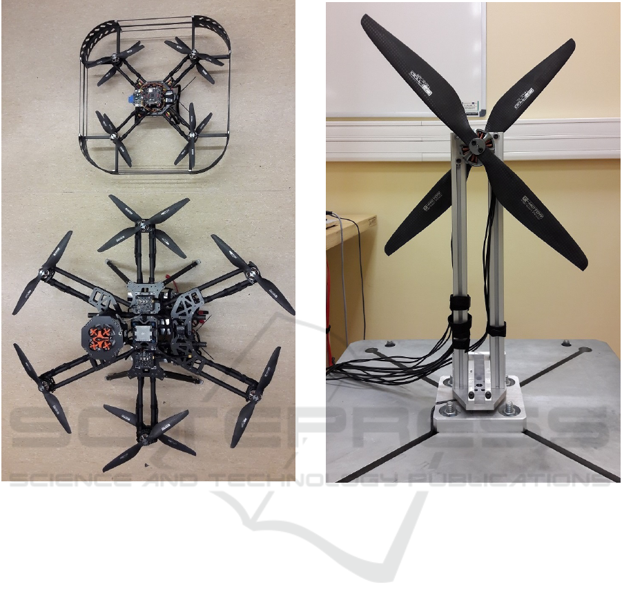
Figure 1: Comparison of Falcon V5 (upper) and Kruk (lo-
wer) UAVs.
be based on the duty cycle of PWM signal as a control
input.
Next step is a simulation development phase. Fir-
stly, it is performed separately for each sub-controller
(Roll, Pitch, Yaw rotation and vertical movement).
Then, the simulation is extended into the full attitude
and vertical movement control. At this point, depen-
dencies between controllers are taken into conside-
ration. In the developed simulation, some additional
blocks are required. First one is a preset signal gene-
ration block which delivers operator command inputs
to the second block - control algorithms. Finally, data
acquisition and presentation block is required to com-
pare tuning results. In rotation and movement model
section, there are parameters defining noise amplitude
on the output signals, which highly affect the perfor-
mance of control algorithms. Those parameters have
to be estimated, but it is better to marginally overesti-
mate than underestimate. In this step, tuning of men-
tioned controllers is performed with manual or auto-
matic techniques.
Figure 2: Propulsion analysis system used in modelling pro-
cess.
Next step is an experimental verification on the
test stand. This phase allows to correct noise para-
meters and fit simulation to the real environment if
needed. If propulsion unit models were formulated
correctly and physical parameters of the structure re-
mained unchanged, selected parameters should allow
the platform to maintain stability. This stage is usu-
ally performed for Roll and Pitch axes because it is
the most popular configuration of rotary test benches.
Moreover, it is hard to construct the test stand with
rotation about Yaw axis and changing altitude, which
would have a negligible effect on the platform mo-
vement.
After those steps, full movement simulation can
be utilised and all parameters of controllers can be
modified to meet desired performance. In this step,
vibration parameters should be slightly increased to
eliminate the dampening effect of the test stand. It
is important to tune controllers in a cautious manner,
because too aggressive parameters in the real environ-
ment may cause instability. It is important to mention,
Initial Tuning Procedure for Attitude and Vertical Movement Controllers in Multirotor Aerial Vehicles with Heterogeneous Propulsion Units
467
that on every step of simulations or experimental veri-
fication it is possible to implement corrections in pa-
rameters to adapt to the real behaviour and meet stated
requirements. Summary of the proposed method was
shortened into following points:
1. Physical CAD modelling of multirotor UAV;
2. Propulsion units experiments on the test rig;
3. Development of models of propulsion units;
4. Formulation of separate simulations for each mo-
vement axes;
5. Implementation of controllers and tuning process;
6. Experimental verification of simulation on the test
stand;
7. Correction of tuned parameters (optional);
8. Formulation of full attitude with vertical mo-
vement simulation;
9. Correction of tuned parameters (optional);
10. Experimental verification during free flight tests;
11. Correction of tuned parameters (optional).
4 MODELLING OF PROPULSION
UNITS
In a majority of mathematical models, the thrust force
generated by propulsion unit is represented by Eq. 1.
F
i
= b
i
· ω
i
; (1)
where: F
i
- force generated by i − th propulsion unit,
b
i
- scaling factor, ω
i
- angular velocity of a propeller.
This method is applicable only to single propulsion
units, which makes harder to represent coaxial setup
with tractor-pusher propeller pair. In addition, in most
cases, no information about the rotational speed is
available in the most UAV sensory systems. There-
fore it has to be omitted and extracted from the PWM
control signal, as the ESCs (Electronic Speed Regu-
lators) keep the blade velocity constant in relation to
the control signal.
Tests were performed on the thrust analysis sy-
stem (Aszkowski et al., 2017) for propulsion units de-
dicated to both considered platforms. Based on gat-
hered data, models were formulated. Thrust model of
units implemented in Falcon V5 platform was deve-
loped in (Ga¸sior et al., 2016b). The same procedure
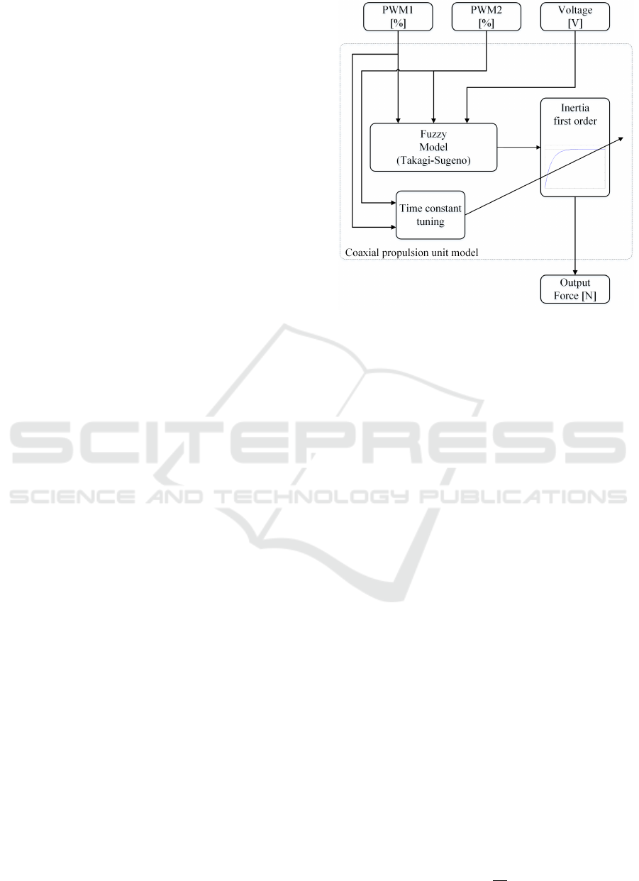
was applied to the ones mounted in Kruk UAV. Block
diagram of mentioned modelling method is shown in
Fig. 3. Two duty cycle signals and supply voltage
measurements are processed by Takagi-Sugeno fuzzy
system, which calculates the thrust. The same met-
Figure 3: Block diagram of a coaxial propulsion unit model.
hod was used in modelling of the reaction torque of
coaxial propulsion unit, which is essential to develop
the simulation of Yaw movement. However, thrust
and reaction force for single propulsion units were
approximated by two dimensional polynomial (x − y,
duty cycle - voltage, with orders for each axis of 3 and
1 respectively).
5 SIMULATIONS
As stated earlier, there are four main areas of develo-
ped simulations during described tuning workflow:
• Roll and Pitch;
• Yaw;
• Vertical movement;
• Roll, Pitch, Yaw and vertical movement in one.
Separated simulations for each axis are formulated
with the Euler’s dynamics equation of a rigid body:
τ = Iα +(ω × Iω), (2)
where: τ - applied torques, α - angular accelerations
of the body, ω - angular velocities of the body and I
- the matrix of moments of inertia. Formulation for
angular accelerations is gathered after several opera-
tions:
α = I
−1
τ − (ω × Iω)
. (3)
Reducing above equations to single axis (ω
y
= ω
z
= 0
and α
y
= α
z
= 0 in case of an X axis) is following:
α
x
=
τ
x
I
xx
. (4)
ICINCO 2018 - 15th International Conference on Informatics in Control, Automation and Robotics
468
Torques are calculated from forces generated by each
propulsion unit and distance from selected symmetry
axis:
τ =
i<n
∑
i=0
d
i
· F
i
, (5)
where: n - number of propulsion units, d
i
- distance
of propulsion unit from rotation axis and F
i
- force
generated by i-th propulsion unit. Positions of each
propulsion unit is gathered from CAD model along
with moments of inertia. Symmetric axes, if possible,
are located the same way as an on-board AHRS (Atti-
tude and Heading Reference System). Torque around
Yaw axis is calculated from the Eq. 5 with reaction
forces generated by each propulsion system and pla-
nar distances to them.
The general method of the single axis simulation
development was presented in (Gasior et al., 2017),
where tuning process of cascade controllers for Fal-
con V5 platform was performed. In the same paper,
the adequacy of simulation has been proven for the
stated platform. As it has been mentioned in Sec. 3,
the first phase of initial tuning is a development of se-
parate simulations for Roll, Pitch, Yaw and vertical
movement. This usually comes down to calculating
angular or vertical acceleration based on generated
thrust and double integrating to gather velocity and
position. Fusion of this method along with additio-
nally required blocks merges into the full simulation.
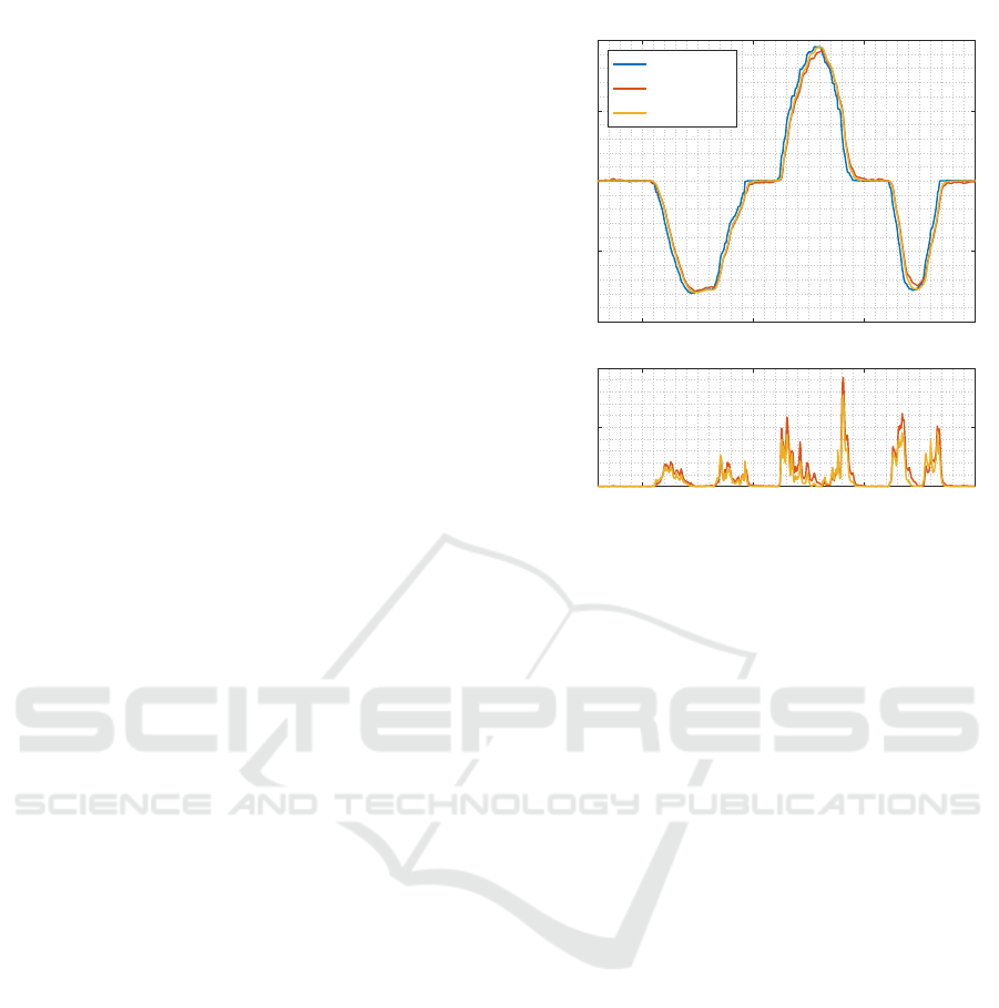
Simulation results of the rotary test bench for the Kruk
platform with a comparison to the experimental data
are shown in Fig. 4. Presented case is performed on
tuned parameters, which also have been used in real
experiment. This example validates the possibility to
tune controllers on the basis of simulation. As can be
seen, tracking quality is satisfactory and squared error
characteristics are very close between two presented
cases.
After tuning and validating controllers in all men-
tioned axes separately, there is a need to merge all
of them into the one system. The overall block dia-
gram of all four simulation components is presented
in Fig. 5. Preset signals are artificially generated or
recreated from recorded flight sequences and passed
to the control block. This section is responsible for
calculating appropriate control signals for propulsion
units. The control structure is design-dependant and
should be identical to the one implemented in avionics
software. The output of this block consists of eight
duty cycle signals which are also design-dependant.
In Falcon V5 and Kruk platform there are always eight
motors implemented, divided into four or six propul-
sion unit respectively. Next step is a calculation of
generated thrust and reaction force, which are there-
after transformed into angular and vertical accelerati-
75 80 85 90
Pitch [°]
-20
-10
0
10
20
Preset
Real
Simulation
Time [s]
75 80 85 90
e
2
0
10
20
Figure 4: Results of the control performance of platform
Kruk in Pitch axis during simulation and real experiment on
the test bench.
ons based on physical parameters from CAD model.
Finally, double integration in both cases allows gat-
hering velocities and positions. In each output, the
noise is added to adapt them to real conditions. These
signals close the loop for the implemented control-
lers. Every simulation is executed with the frequency
equal to the refresh rate of a control loop in the main
on-board controller.
Tuning process should be performed sequentially,
one controller at a time. Parameters selected in the
individual simulations should be used as initial ones
in the merged simulation. Experimental verification
is described in the following section.
6 EXPERIMENTS AND TUNING
RESULTS
With the fully developed and tuned simulations, the
next step is to conduct experimental validation. The
first phase was performed on the rotary test stand sho-
wed in Fig. 6. This device fixes the UAV movement
and reduces degrees of freedom to only one rotatio-
nal axis. In this configuration, Roll and Pitch con-
trollers can be validated. Exemplary characteristics
from one experiment with Kruk platform are presen-
ted in Fig. 4, where Pitch axis was concerned. As can
be seen, the controller has a good performance and
maintains tracking during the whole sequence. The
squared error remains within reasonable limits. The
Initial Tuning Procedure for Attitude and Vertical Movement Controllers in Multirotor Aerial Vehicles with Heterogeneous Propulsion Units
469
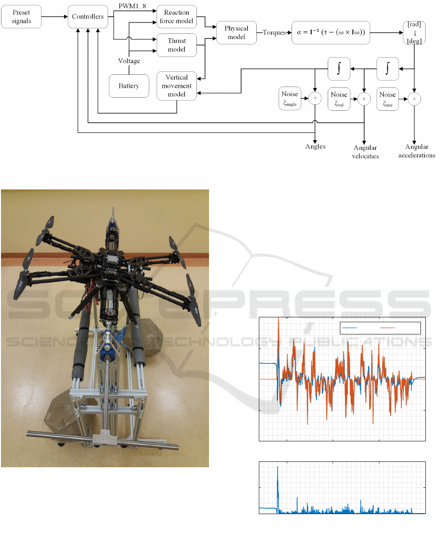
Figure 5: Block diagram of Roll, Pitch, Yaw and vertical movement simulation.
Figure 6: Platform Kruk mounted on the test stand in Pitch
axis.
highest points in error characteristics are present du-
ring rapid changes in preset signal, where controllers’
response is slightly slower.
After positive verification on the test bench, the
oncoming step is a free flight experiment performed
in order to check the performance of the Yaw and ver-
tical movement controllers. It is advised to implement
them sequentially, firstly Roll, Pitch and Yaw with
throttle control, and finally with vertical movement
turned on. This approach reduces the number of pos-
sible errors during implementation and allows to lo-
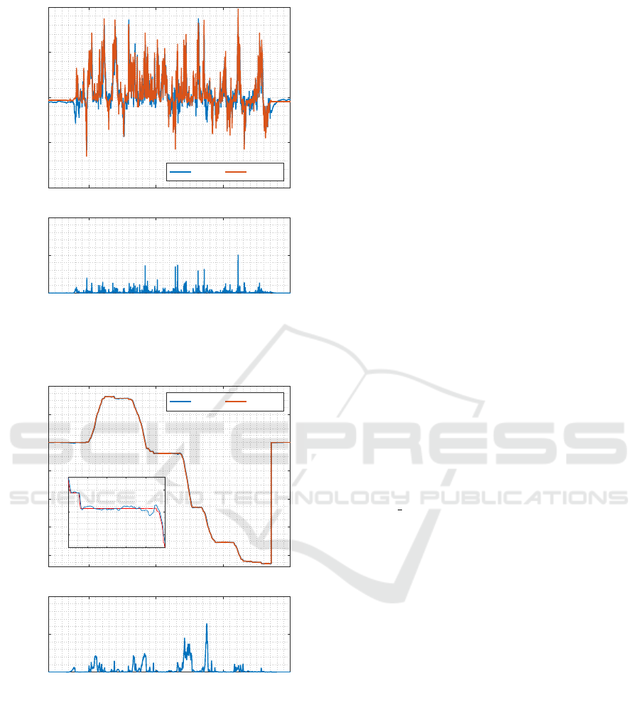
cate them more accurately. Three characteristics from
exemplary free flight are presented in Fig. 7, 8 and 9,
representing Roll, Pitch and Yaw respectively. Con-
trollers with parameters selected during the simula-
tion phase managed to correctly track preset signal
which was very dynamic because of a characteristic
of the performed mission. Errors in all three exam-
ples were comparable, but the highest divergence has
been observed in Yaw controller. This could be the
result of wind gusts during flying through corridors.
450 500 550 600
Roll [°]
-4
-2
0
2
4
Angle Preset
Time [s]
450 500 550 600
e
2
0
5
10
Figure 7: Results of the control performance of platform
Kruk in Roll axis during real flight.
Experiments on controllers of vertical velocity has
been performed in (Gasior et al., 2017) for Falcon V5
platform. Unfortunately, these experiments have not
been completed so far for the Kruk UAV.
ICINCO 2018 - 15th International Conference on Informatics in Control, Automation and Robotics
470
450 500 550 600
Pitch [°]
-4
-2
0
2
4
Angle Preset
Time [s]
450 500 550 600
e
2
0
10
20
Figure 8: Results of the control performance of platform
Kruk in Pitch axis during real flight.
450 500 550 600
Yaw [°]
-200
-150
-100
-50
0
50
100
Angle Preset
500 505 510 515
-25
-20
-15
Time [s]
450 500 550 600
e
2
0
10
20
Figure 9: Results of the control performance of platform
Kruk in Yaw axis during real flight.
7 CONCLUSIONS AND FUTURE
WORK
Presented method of initial tuning of the controllers’
parameters proven itself in real life scenarios. It was
tested during modification of control scheme for the
Falcon V5 platform and initial tuning for the Kruk
UAV. It is important to mention, that the complete
model of analysed multirotor UAV is not required to
achieve satisfactory results. This affects the develop-
ment time, which can be reduced by eliminating the
calibration process of the mentioned model.
One of the key points of the described method is
a model of propulsion unit, which is the foundation
to all of the simulations. Thanks to its flexibility, this
method is extremely useful to simulate unsymmetri-
cal platforms with heterogeneous propulsion units.
In the future work, authors plan to finish the ex-
perimental verification process of the vertical mo-
vement controller for the Kruk UAV. Moreover, com-
parison with state-of-the-art initial tuning techniques
will be performed. Finally, automatic tuning algo-
rithms for different types of controllers will be im-
plemented to simplify comparison process and para-
meterise tracking performance with an adequate cost
function.
ACKNOWLEDGEMENTS
This research was funded by the Poznan Univer-
sity of Technology grant DSPB/0162. In addition,
part of this work concerning the Kruk platform,
was co-financed by the European Regional Develop-
ment Fund under the Smart Growth Operational Pro-
gramme 2014-2020 under the Operation 1.2 - Contest
1/1.2/2015 INNOLOT.
REFERENCES
Aszkowski, P., Błoszyk, K., Bondyra, A., Ga¸sior, P., and
Giernacki, W. (2017). UAV propulsion analysis sy-
stem with reconfigurable controller feature. Measure-
ment Automation Monitoring, 63(5):171–173.
Bondyra, A., Gardecki, S., Ga¸sior, P., and Giernacki, W.
(2016). Performance of coaxial propulsion in design
of multi-rotor UAVs. In Challenges in Automation,
Robotics and Measurement Techniques, pages 523–
531. Springer.
Bondyra, A., Gasior, P., and Gardecki, S. (2017). Experi-
mental test bench for multirotor UAVs. In Internatio-
nal Conference Automation, pages 330–338. Springer.
Bouabdallah, S. and Siegwart, R. (2007). Full control of
a quadrotor. In Intelligent robots and systems, 2007.
IROS 2007. IEEE/RSJ international conference on,
pages 153–158. Ieee.
Connor, J., Seyedmahmoudian, M., and Horan, B. (2017).
Using particle swarm optimization for PID optimiza-
tion for altitude control on a quadrotor. In Univer-
sities Power Engineering Conference (AUPEC), 2017
Australasian, pages 1–6. IEEE.
Initial Tuning Procedure for Attitude and Vertical Movement Controllers in Multirotor Aerial Vehicles with Heterogeneous Propulsion Units
471

Dikmen,
˙
I. C., Arisoy, A., and Temeltas, H. (2009). Attitude
control of a quadrotor. In Recent Advances in Space
Technologies, 2009. RAST’09. 4th International Con-
ference on, pages 722–727. IEEE.
Ga¸sior, P., Bondyra, A., Gardecki, S., and Giernacki, W.
(2016a). Robust estimation algorithm of altitude and
vertical velocity for multirotor UAVs. In Methods
and Models in Automation and Robotics (MMAR),
2016 21st International Conference on, pages 714–
719. IEEE.
Ga¸sior, P., Bondyra, A., Gardecki, S., Giernacki, W., and
Kasi
´
nski, A. (2016b). Thrust estimation by fuzzy mo-
deling of coaxial propulsion unit for multirotor UAVs.
In Multisensor Fusion and Integration for Intelligent
Systems (MFI), 2016 IEEE International Conference
on, pages 13–18. IEEE.
Gasior, P., Bondyra, A., Gardecki, S., and Kasinski, A.
(2017). Cascade control algorithms of position and
attitude for multirotor UAV. In Methods and Models
in Automation and Robotics (MMAR), 2017 22nd In-
ternational Conference on, pages 47–52. IEEE.
Hoffmann, F., Goddemeier, N., and Bertram, T. (2010).
Attitude estimation and control of a quadrocop-
ter. In Intelligent Robots and Systems (IROS), 2010
IEEE/RSJ International Conference on, pages 1072–
1077. IEEE.
Howard, D. (2017). A platform that directly evolves multi-
rotor controllers. IEEE Transactions on Evolutionary
Computation, 21(6):943–955.
Panizza, P., Invernizzi, D., Riccardi, F., Formentin, S., and
Lovera, M. (2016). Data-driven attitude control law
design for a variable-pitch quadrotor. In American
Control Conference (ACC), 2016, pages 4434–4439.
IEEE.
Tayebi, A. and McGilvray, S. (2006). Attitude stabilization
of a VTOL quadrotor aircraft. IEEE Transactions on
control systems technology, 14(3):562–571.
Wang, L. and Poksawat, P. (2017). Automatic tuning of
hexacopter attitude control systems with experimen-
tal validation. In System Theory, Control and Com-
puting (ICSTCC), 2017 21st International Conference
on, pages 753–758. IEEE.
ICINCO 2018 - 15th International Conference on Informatics in Control, Automation and Robotics
472
