
Design of a Saw Cutting Machine for Wood and Aluminum
Jawad Ul Haq
1
, Ahmed Jawad Qureshi
1
and Mohamed Al-Hussein
2
1
Department of Mechanical Engineering, University of Alberta, Canada
2
Department of Civil and Environmental Engineering, University of Alberta, Canada
Keywords: Axiomatic Design, Table Saw, Programmable Logic Controller, Control System, Automation.
Abstract: The intensive use of wood in furniture, building, bridges, and of aluminum in transportation and construction,
underscores the economic importance of these building materials in North America. Power saws are very
useful tools for cutting and shaping such materials; however, they can cause serious hand injuries. In a table
saw operation for wood cutting, for instance, the operator’s hands are vulnerable as they are used to guide
pieces into the saw. In addition, the saw operator faces the risk of material being kicked back out of the saw
or of sustaining an eye or respiratory injury due to the presence of sawdust and other debris generating by the
operation of the saw. Meanwhile, aluminum cutting requires careful precaution and accuracy. The cutting can
be dangerous if not handled properly. The greatest challenge in this regard is securely holding the material
being cut. Furthermore, industrial requirements such as pneumatics and three-phase power supply preclude
the ready use of such machines on a domestic scale. The cutting capability of existing table saws is coupled
in such a way that it cannot cut both wood and aluminum. In this paper, a concept of a saw cutting machine
(SCM) is presented using Axiomatic Design to ensure design objectives such as safety, user comfort, usage
on a domestic scale and capability to cut both types of materials. In the presented case study, the mapping
from Customer Attributes (CAs) to Functional Requirements (FRs) and then respective Design Parameters
(DPs) resulted in an uncoupled design, in turn leading to a detailed mechanical design followed by the control
system, all based on the aforementioned design objectives.
1 INTRODUCTION
Forest products are a major contributor to the
Canadian economy. (Canada, 2013) In 2013,
production in the forestry sector contributed $19.8
billion to the economy. In a global context, Canada
has the world’s largest forest product trade balance.
The aluminum industry is another important sector of
Canada’s economy, with aluminum products export
valued at $10.8 billion in 2016, an increase of $211
over 2015; (Canada ranks third in aluminum
production in the world after China, and Russia).
The motivation for the development of the saw
cutting machine (SCM) described in this paper arose
out of a broader research initiative at the University
of Alberta (Canada) to develop a semi-automated
wood framing machine
Figure 1 and a semi-automated light-gauge steel
framing machine Figure 2. The primary objective of
both machine development projects is to support the
growth of panelized construction in North America’s
building construction sector. The structures of both
machines consist of aluminum extrusions that need to
be cut in different lengths and angles. The lab has to
outsource the cutting to third-party companies,
resulting in increased costs and delays of the machine
development program.
In order to overcome the aforementioned
challenges, the research team began investigating
SCM solutions with the design objectives of (1) the
ability to cut both wood and aluminum, (2) versatility
to be deployed in a lab or domestic scale without
three-phase industrial power supply or complex
pneumatics, (3) safety mechanisms to enable safe use,
Figure 1: Wood framing machine.
456
Haq, J., Qureshi, A. and Al-Hussein, M.
Design of a Saw Cutting Machine for Wood and Aluminum.
DOI: 10.5220/0006909704560464
In Proceedings of the 15th International Conference on Informatics in Control, Automation and Robotics (ICINCO 2018) - Volume 2, pages 456-464
ISBN: 978-989-758-321-6
Copyright © 2018 by SCITEPRESS – Science and Technology Publications, Lda. All rights reserved
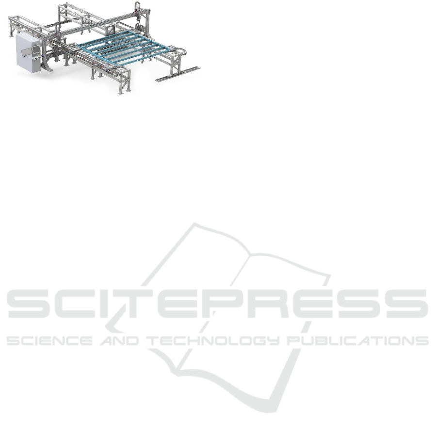
Figure 2: Steel framing machine.
and (4) capable of angled cutting started and resulted
in a design discussed in the following sections.
In order to overcome the aforementioned
challenges, the research team began investigating
SCM solutions with the design objectives of (1) the
ability to cut both wood and aluminum, (2) versatility
to be deployed in a lab or domestic scale without
three-phase industrial power supply or complex
pneumatics, (3) safety mechanisms to enable safe use,
and (4) capable of angled cutting started and resulted
in a design discussed in the following sections.
The paper is divided into eight sections. Section 2
reviews the relevant literature with a focus on
potential safety hazards, Section 3 elaborates on the
design objectives and describes the research
methodology, Section 4 explains the implementation
of Axiomatic Design to form an uncoupled design,
Section 5 presents the mechanical design, and Section
6 the implementation of the control system to meet
the design objectives mentioned in Section 3. Section
7 describes the discrete-event simulation model of the
SCM, followed by Section 8, which summarizes the
research achievements.
2 LITERATURE REVIEW
Table saws are associated with more injuries than any
other type of woodworking tool.(Shields, Wilkins and
Smith, 2011) estimate that 565,670 table-saw related
injuries were treated in the United States during the
period 1990–2007. Injuries to fingers/thumbs were
the most common overall (86%—486,181 of
565,670). (Chung and Shauver, 2013) discuss
SawStop, a technology designed to stop the saw blade
when contact is made with skin, resulting in a small
cut rather than a serious laceration or amputation. A
few disadvantages associated with SawStop, though,
are that the force required to quickly stop the saw
blade damages the blade and brake beyond repair
such that they must be replaced each time the brake is
triggered; furthermore, the brake cartridges are blade-
specific; there are no brakes available for some
specialty blades; and brakes can only be used when
cutting nonconductive materials. (Graham and
Chang, 2015) provide a quantitative estimate of the
economic benefits of automatic protection systems
that could be deployed in new table saw products. The
general consensus among researchers is that the
benefits of automatic protection are likely to
outweigh the incremental costs of implementation
significantly. (Schwaneberg et al., 2012) discuss the
use of a LED-based sensor system to distinguish
human skin from work pieces. In this context, it is
thus of interest to investigate new technology to
automate the process by designing a machine using a
systematic method of design. (Farid and Suh, 2016)
Axiomatic design is a design method introduced by
Nam P. Suh. It consists of four domains: consumer,
functional, physical, and process. These domains are
interlinked in such a way that customer needs—
referred to as customer attributes (CAs)—in the
customer domain are transformed into functional
requirements (FRs) in the functional domain. FRs, in
turn, are satisfied by design parameters in the physical
domain. Product variables (PVs) are determined from
DPs in the same manner. Axiomatic design as
described above has been used in many fields, such
as software design (Suh and Do, 2000) and control
system design (Lee, Suh and Oh, 2001). (Negahban
and Smith, 2014) provide a comprehensive review of
discrete-event simulation in which the discrete-event
model of a system can be implemented using a
computer. This simulation-based approach can aid in
understanding the system under study in terms of
cycle time, utilization of different resources,
improvements in design, and production levels.
3 METHODOLOGY
The design objectives for the machine are as follows:
• Capable of cutting both wood and aluminum
• Can be used in a lab or domestic scale
• Ensures safety and operator comfort
• Can accommodate angled cutting
In general, the design of machines consists of
conceptual and detailed design processes. Overall the
factors which affect the most characteristics and the
cost are determined in the conceptual stage.
Axiomatic design is a design methodology to
systematically transform the CAs into FRs and then
respective DPs, and PVs. In this paper; Axiomatic
design is utilized in the conceptual design process that
further lead to detailed design. The FRs for the SCM
Design of a Saw Cutting Machine for Wood and Aluminum
457
are defined on the basis of CAs, and corresponding
DPs are selected. The detailed design is carried out on
the basis of decisions made in the conceptual stage.
Computer Aided Design (CAD) model of the SCM is
developed in SOLIDWORKS. Control system of the
SCM is realized on Programmable Logic Controller
(PLC) using Sequential Function Chart (SFC) which
is one of the IEC 61131-3 languages. In order to
estimate the performance of the machine, discrete-
event modelling technique is used. Arena input
analyzer by Rockwell automation is used to select the
distribution of each task in the simulation model.
4 AXIOMATIC DESIGN
Design process in Axiomatic design is top-down, in
which the initial concept is decomposed to design
details by zigzagging. The relationship between FRs
and DPs is given as
{FRs} = [A] {DPs} (1)
FRs are a minimum set of independent requirements
that completely characterize the functional needs of
the product in the functional domain. Each FR is
independent of every other FR at the time the FRs are
created. [A] is defined as the design matrix. When [A]
is the diagonal matrix, the design is called uncoupled
design which is ideal. When [A] is lower triangular
matrix, the design is called decoupled and preferred
in absence of uncoupled, while all the other designs
are called coupled. DPs are the physical variables in
the physical domain that characterize the design that
satisfies the specified FRs. When DPs do not take
their detailed physical form, the corresponding FRs
need further division. Based on DP
3
, FR
3
of the SCM
is decomposed into two sections as FR
3.1
and FR
3.2.
The FR
5
needs no further decomposition as DP
5
has
taken its detailed physical form.
The axiomatic design of SCM has three parts:
CAs, FRs, and DPs. At the beginning of the design
process, the needs of the customers (i.e., CAs) are
taken into account in order to generate the FRs and
then the DPs. The top-level design is given as
follows:
CA: Wood and aluminum cutting capability, safety,
user comfort, usage on a domestic scale, and angled
cutting capability.
FR
0
: Carry saw, motors, sensors (electrical
components) inside a safe cabinet (mechanical)
DP
0
: Programmable logic controller (PLC)-
controlled saw cutting machine
After the top level design, FRs and DPs are
decomposed and Table 1 illustrates the second level
FRs and DPs.
FR
3
= Facilitate operator
FR
4
= Industry power & pneumatics alternative
FR
5
= Angle cut
FR
6
= Safety
DP
3
= Automation using stepper motors & Human
Machine Interface (HMI)
DP
4
= Single phase power supply & force controlled
actuators
DP
5
=Rotary table
DP
6
= Sensors based mechanical assembly
The low level FRs and DPs decomposition is as
follows:
FR
3.1
= Use automation
FR
3.2
= Facilitate interaction with machine
FR
4.1
= Use domestic power
FR
4.2
= Use pneumatics alternative
FR
6.1
= Incorporate safety measures against airborne
debris
FR
6.2
= Make sure user is at a safe distance
DP
3.1
= Motors
DP
3.2
= Human Machine Interface
DP
4.1
= Single phase power supply
DP
4.2
= Forced controlled actuators
DP
6.1
= Safety enclosure
DP
6.2
= Ultrasonic sensors
Table 1: Initial design matrix.
FRs/DPs
1 Cut wood
2 Cut aluminum
1.1 Cutting RPM
1.2 Cutting
feed speed
1 Need to cut
wood
x
1.1 Use
cutting RPM
x x
1.2 Use feed
speed
x x
2 Need to cut
aluminum
x
2.1 Use
cutting RPM
x x
2.2 Use feed
speed
x x
ICINCO 2018 - 15th International Conference on Informatics in Control, Automation and Robotics
458
Table 2: Low level design matrix.
FRs/DPs
1.1 Apply cutting
wood RPM
1.2 Apply cutting
wood feed speed
2.1 Apply cutting
aluminum RPM
2.2 Apply cutting
aluminum feed speed
3.1 Stepper motors
3.2 Human Machine
Interface
4.1 Single phase
power supply
4.2 Force controlled
actuators
6.1 Safety enclosure
6.2 Ultrasonic sensors
1.1 Use cutting RPM
x
1.2 Use feed speed
x
2.1 Use cutting RPM
x
2.2 Use feed speed
x
3.1 Use automation
x
3.2 Ease interaction with machine
x
4.1 Use domestic power
x
4.2 Use pneumatic alternative
x
6.1 Incorporate safety measures
against airborne debris
x
6.2 Make sure user is at a safe
distance
x
The one obvious coupling which is not discussed for
this case study is the type of saw. A universal saw is
proposed to uncouple the design; although this will
compromise the quality of the cut in the case of
aluminum, it satisfies the design objectives and the
purpose for which the machine is being designed.
Feed speed =
× ×
(2)
Feed speed: inches per minute
RPM: revolutions per minute
Chip load: inches
The initial design matrix results in a coupled design
due to the fact that feed speed and RPM are related
(2). Feed speed and RPM have to be adjusted
according to the material being cut. The second
concern is that the number of FRs is greater than the
number of DPs. The first step towards uncoupling the
initial design is a permutation that results in a better
design but still a coupled one. To solve the issue of
feed speed and RPM coupling, a software solution is
used which is implemented on PLC that sets the
desired feed speed and RPM to cut the given material.
The second design issue of inequality in numbers of
FRs and DPs is addressed by adding more DPs to
make the design matrix square. The final uncoupled
design matrix is shown in Table 2.
5 MECHANICAL DESIGN
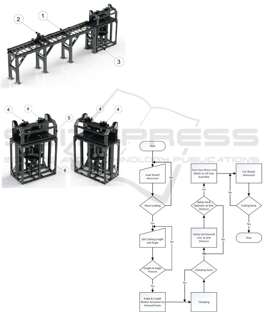
The CAD model of the SCM as shown in Figure 3 and
Figure 4 is developed in SOLIDWORKS, a solid
modelling computer-aided design tool that runs on a
computer. The machine design is flexible, it should
be noted, with regard to the length of material to be
cut. Depending on the length of the profile the table
can be attached along with a motor-controlled length
measurement unit, or the profile can be put directly
on the main cutting station. The force-controlled
actuators are used to clamp the piece firmly. A safety
enclosure protects against any debris or particle
hitting the operator while working, and the rotary
table is used to achieve the cut angle.
1. Table
2. Cutting length measurement unit
3. Main cutting station
4. Force-controlled actuators
5. Safety enclosure
6. Rotary table
Design of a Saw Cutting Machine for Wood and Aluminum
459
6 CONTROL SYSTEM
Machine control system is a collection of hardware
and software, designed to coordinate the output of
each individual component to achieve the desired
machine functionality.
Figure 3: SCM CAD model.
Figure 4: SCM main cutting station.
6.1 Process Flow
The process as shown in Figure 5 starts with the
manual loading of the wood/aluminum profile. A
human–machine interface (HMI) is used to obtain the
desired length and angle to be cut, followed by
clamping in which load sensors are used to apply the
required force to clamp the wood or aluminum being
cut. The saw motor waits for the safety enclosure to
come down and for the operator to move a safe
distance away.
6.2 Sequence of Operation
The sequence of operations consists of (1) loading;
(2) length and angle input; (3) clamping; (4)
engagement of safety enclosure and sensors for
operator’s safety; and (5) engagement of saw motor
and feed motor to cut material.
Loading is the manual operation in which the
operator picks a profile and places it in the designated
area of the machine. Once the loading is done, the
next step is to input material and cut specifications.
The HMI facilitates the interaction between the
operator and the machine. The information is inputted
to the machine by either of two methods. In the first
method, a computer numerical control (CNC) file
containing the complete information about the profile
is uploaded, and the machine reads the file in a
sequential manner to perform the operation. The CNC
file contains information such as the material,
coordinates, and angle to cut. In the second method,
the operator loads the profile and inputs the
information manually. Once the operator has inputted
the information, the machine executes safety
measures before carrying out the cutting operation. It
looks for a valid CNC file or coordinates to cut,
ensures by means of ultrasonic sensors that the
operator is at a safe distance, clamps the profile, and
engages the safety enclosure. If all the conditions are
met, then the PLC sends a command to the saw motor
to engage and perform the cut. Apart from these
safety checks, there are also emergency shutdown
(ESD) push-buttons which can be used to halt the
Figure 5: Process flow chart.
ICINCO 2018 - 15th International Conference on Informatics in Control, Automation and Robotics
460
machine in case of any abnormal scenario. To clamp
and
to replace the pneumatic system, feedback force-
controlled actuators are used. Based on the material
selected, the actuators apply the right amount of force
and the feed motor selects the desired feed speed to
cut the material. Once the material is cut, it is
unclamped in order for the operator to collect it.
6.3 Implementation of Control System
Automation of the sequence of operation is realized
by means of PLC as follows:
• Discrete inputs from proximity sensors for
wood/aluminum detection.
• Discrete inputs from limit switches for safety
and initial calibration.
• Analog inputs from load sensors to clamp
wood/aluminum.
• Analog inputs from ultrasonic sensors for
operator safety.
• Motor drive outputs to linear actuators for
clamping.
• Motor drive outputs to cut wood/aluminum at
desired angle and length.
• HMI to facilitate the automation process.
Once the hardware is known, next step is to select the
software to make harware operational. The PLC code
is developed in SoMachine, while the HMI code is
developed in Schneider Electric’s Vijeo Designer.
(Electric, 2018b) SoMachine is a software tool for
developing, configuring, and commissioning the
entire machine in a single software environment,
including logic, motion control, and related network
automation functions while Vijeo Designer is an HMI
configuration software. (Plaza, Medrano and Blesa,
2006) IEC 6113-3 standard is a global standard for
control programming that helps to improve software
quality. Ladder programming has several drawbacks,
including weak software structure and limited capacity
to handle complex data structures. (Jetley et al., 2013)
discuss the comparison of graphical IEC 61131-3
programs, asserting that it is easier to trace the error
with graphical languages as compared to textual.
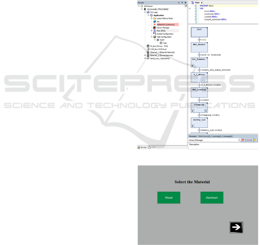
6.3.1 Implementation of Code
The code for SCM is written in Sequential Function
Chart (SFC), which is one of the IEC 61131-3 langua-
ges. Each block in SFC has three portions: entry, main
body, and exit conditions. The program flows through
these portions in a sequential manner. The flow
between blocks is governed by transitions, which are
conditions the satisfaction of which drives the flow of
the program on to the next block as shown in Figure 6.
6.3.2 Implementation of HMI
Vijeo Designer provides great flexibility in designing
graphical user interfaces (GUIs), where the nature of
the operator’s interaction with the machine dictates
the design of the HMI. A well designed HMI aids the
operator in understanding the previous, ongoing, and
future tasks. It provides great advantages in terms of
providing a user-friendly interface even for users
without a relevant technical background, in which
warnings and emergency situations can be communi-
cated more efficiently by using bright colors to attract
the operator’s attention, and a single button can be
assigned multiple tasks providing more flexibility in
Figure 6: SCM code in SoMachine.
Figure 7: Material selection in Vijeo Designer.
Design of a Saw Cutting Machine for Wood and Aluminum
461
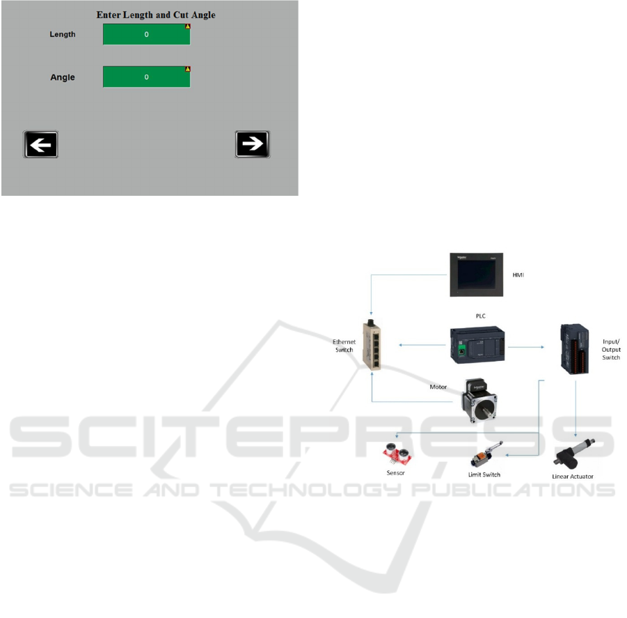
Figure 8: Operator input in Vijeo Designer.
terms of coding. The GUI implementation in Vijeo
Designer is shown in Figure 7 and Figure 8.
6.4 Ethernet/Ip Architecture
One of the complex tasks in the development of PLC-
based control systems is wiring. Having a relatively
small numbers of devices in a control system can
result in a complex wiring system which occupies
more space and is difficult to troubleshoot. (Electric,
2018a) Ethernet/IP uses two protocols for the
transport layer: Transmission Control Protocol (TCP)
and User Data Datagram Protocol (UDP). TCP is
acknowledged while UDP is unacknowledged
protocol. TCP is used for non-control messages while
UDP is used for Input/output (I/O) messages. Tested
validated document and architecture (TVDA)-based
Ethernet/IP improves efficiency in the design and
planning phase. Based on inputs/outputs described in
Section 6.3 Ethernet/IP architecture is used for the
machine described in this paper due to the following
advantages:
• Ability to access the machine from anywhere,
anytime via Ethernet for remote monitoring.
• Flexible in terms of adding an Ethernet/IP
adaptor at any time.
• Efficient in terms of device integration and
configuration, and the architecture can easily
be modified.
With embedded Ethernet/IP communication, a
PLC can communicate with 16 slaves in 10 ms. The
Ethernet/IP architecture for the SCM is given in
Figure 9.
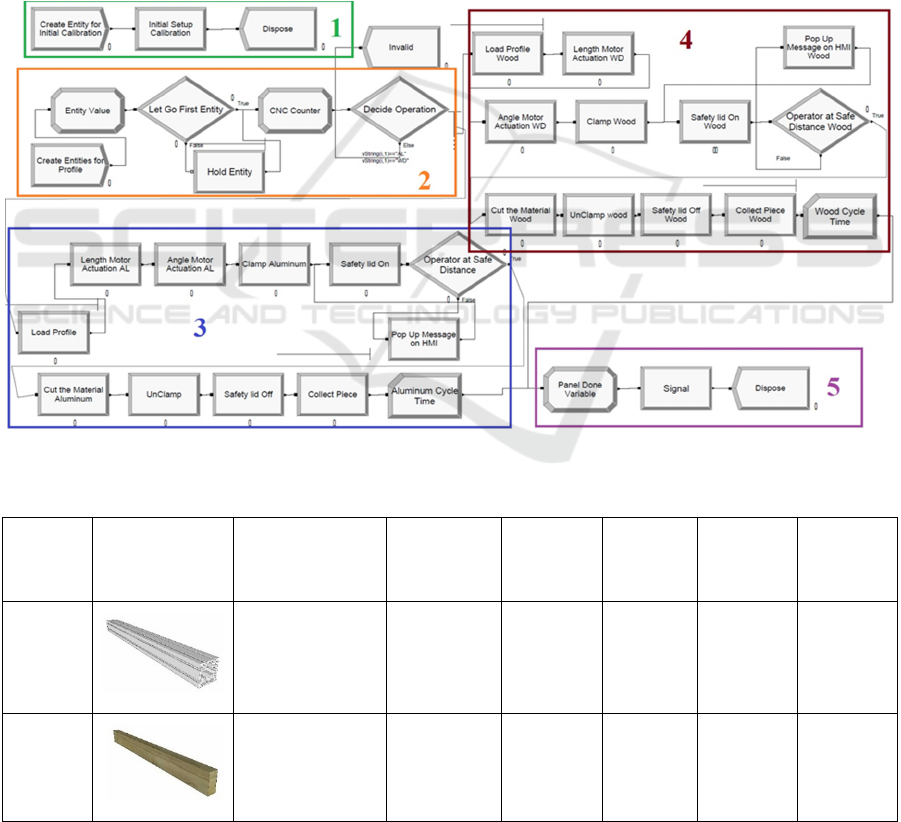
7 DISCRETE EVENT
SIMULATION
Discrete-event simulation describes a process with a
set of unique, specific events in time. Arena by
Rockwell automation is used in the present research
to build the SCM model with its key performance
parameters such as cycle time and operator
utilization. The model as shown in Figure 10 reads a
CNC file that contains information about a profile,
such as material, cut coordinates, and cut angle, in a
sequential manner. The task times and triggers are
assumed to provide the basis for statistical analysis
and hypothesizing distribution.
Figure 9: SCM Ethernet/IP architecture.
7.1 Model Discussion
A discussion of the simulation model is given in this
section. In Arena, a model is built using a “process”
module that holds the “entities” for a specific period
of time. The entities flow through different process
modules to provide a valuable insight into machine’s
key performance indicators at the end of the
simulation. The model for the SCM reads a
spreadsheet extracted from a CNC file and scans the
total number of cutting operations in the file prior to
processing. It then generates entities equal to the
number of cutting operations. The “Hold Entity”
module holds the next entity, which is the next cutting
operation, until the previous entity, which is the
previous cutting operation being processed by the
model, finishes. The “Decide Operation” module
decides the material on the basis of a string variable
that looks for either “WD” for wood or “AL” for
aluminum in the file and then guides the respective
entity to pass through the modules designated for the
respective material. The “Load Profile” and “Collect
ICINCO 2018 - 15th International Conference on Informatics in Control, Automation and Robotics
462
Piece” modules share a common resource, which is
the operator. The “Length” and “Angle” module task
times, it should be noted, are dependent on the
coordinates and proportional to the cut length and
angle in the CNC file. The model consists of
following main modules sections (1) initial
calibration; (2) CNC file reading; (3) aluminum
cutting; (4) wood cutting; and (5) ending. (1) accounts
for the time taken in homing the motors and initial
system delays when the machine is powered on, (2)
deals with reading of the CNC file and deciding the
operations accordingly, (3) accounts for the time
taken in cutting the aluminum, (4) accounts for the
time taken in cutting wood, and (5) indicates when all
the operations on the profile are done.
7.1.1 Case Study
To illustrate the effect of different profiles with
different cut and angle coordinates on the key
performance indicators, for instance, cycle time and
utilization of the operator, Table 3 shows the
summary of results obtained from the model. For the
profile case studies as illustrated in Table 3, the
simulation model generates a total of five entities, as
there are five cutting operations at time zero. The
“Hold Entity” module holds the next cutting
operation until the previous entity or cutting operation
exits the model, and sends a trigger to the hold
module through the signal module. The simulation
keeps running until all the entities generated have
exited the model.
Figure 10: SCM simulation model.
Table 3: Simulation results summary.
Profile Dimensions
WxHxL
(inch)
Material Cut Lengths
(inch)
Cut Angle
(θ)
Average
Cycle Time
(minute)
Average
Operator’s
Utilization
(%)
Profile 1
1.57x1.57x78.74 Aluminum 12,24,48 45,60,0 3.3 81
Profile 2
1.5x3.5x78.74 Wood 12,36 0,0 2.1 70
Design of a Saw Cutting Machine for Wood and Aluminum
463

8 CONCLUSION
The traditional method for cutting wood using a table
saw involves a stationary saw motor in which the
wood is fed through the saw by hand. This approach
entails serious safety hazards. On the other hand,
aluminum cutting requires extra precaution and
careful craftsmanship to ensure an accurate cut, and
the cutting can be dangerous if not executed properly.
Given the inherent risks of conventional sawing
practice, limitations of cutting both materials,
benefits of automation and to support panelized
construction, in this paper Axiomatic design theory is
applied for investigating the problems of the present
table saws and for designing an uncoupled new one.
As a result of maping from functional domain to
physical domain, the feed speed and RPM for wood
and aluminum cutting found to be coupled. A
complete control system strategy from defining the
process flow to its full implementation was crafted to
meet the design objectives and based on the analysis
an uncoupled design of saw cutting machine is
introduced. Discrete event modelling is employed to
estimate the performance of the machine and
implication of different sizes of profiles. The
simulation results provide valuable insight into
machine’s key performance indicators, for instance,
cycle time and operator’s utilization.
REFERENCES
Canada, N. R. (2013) Forest and Aluminum Industry.
Available at: http://www.nrcan.gc.ca
Chung, K. C. and Shauver, M. J. (2013) ‘Table Saw
Injuries’, Plastic and Reconstructive Surgery, 132(5),
p. 777e–783e. doi: 10.1097/PRS.0b013e3182a3bfb1.
Electric, S. (2018a) Industrial Ethernet. Available at:
https://www.schneider-electric.com/en/product-range-
presentation/1106-industrial-ethernet?parent-category-
id=2400&parent-subcategory-
id=2410&filter=business-1-Industrial Automation and
Control.
Electric, S. (2018b) SoMachine. Available at: https://www.
schneider-electric.ca/en/product-range-presentation/22
26-somachine#tabs-top.
Farid, A. M. and Suh, N. P. (2016) Axiomatic Design in
Large Systems. doi: 10.1007/978-3-319-32388-6.
Graham, J. D. and Chang, J. (2015) ‘Reducing the risk of
injury from table saw use: The potential benefits and
costs of automatic protection’, Risk Analysis, 35(2), pp.
307–317. doi: 10.1111/risa.12258.
Jetley, R., Rath, A., Aparajithan, V., Kumar, D., Prasad, V.
and Ramaswamy, S. (2013) ‘An approach for
comparison of IEC 61131-3 graphical programs’, IEEE
International Conference on Emerging Technologies
and Factory Automation, ETFA. doi: 10.1109/
ETFA.2013.6647938.
Lee, K. D., Suh, N. P. and Oh, J. H. (2001) ‘Axiomatic
design of machine control system’, CIRP Annals -
Manufacturing Technology, 50(1), pp. 109–114. doi:
10.1016/S0007-8506(07)62083-6.
Negahban, A. and Smith, J. S. (2014) ‘Simulation for
manufacturing system design and operation: Literature
review and analysis’, Journal of Manufacturing
Systems. The Society of Manufacturing Engineers,
33(2), pp. 241–261. doi: 10.1016/j.jmsy.2013.12.007.
Plaza, I., Medrano, C. and Blesa, A. (2006) ‘Analysis and
implementation of the IEC 61131-3 software model
under POSIX Real-Time operating systems’,
Microprocessors and Microsystems, 30(8), pp. 497–
508. doi: 10.1016/j.micpro.2006.06.001.
Schwaneberg, O., Steiner, H., Bol\’ivar, P. H. and Jung, N.
(2012) ‘Design of an LED-based sensor system to
distinguish human skin from workpieces in safety
applications’, Appl. Opt., 51(12), pp. 1865–1871. doi:
10.1364/AO.51.001865.
Shields, B. J., Wilkins, J. R. and Smith, G. A. (2011)
‘Nonoccupational Table Saw-Related Injuries Treated
in US Emergency Departments, 1990–2007’, The
Journal of Trauma: Injury, Infection, and Critical
Care, 71(6), pp. 1902–1907. doi: 10.1097/TA.0b
013e3181b28ad3.
Suh, N. P. and Do, S.-H. (2000) ‘Axiomatic Design of
Software Systems’, CIRP Annals - Manufacturing
Technology, 49, pp. 95–100. doi: 10.1016/S0007-
8506(07)62904-7.
ICINCO 2018 - 15th International Conference on Informatics in Control, Automation and Robotics
464
