
Root Cause Analysis of Deep Drawing Processes with Superimposed
Low-Frequency Vibrations on Servo-Screw Presses
A Practical Research on Predictability in Simulation
André Sewohl
1
, Sebastian Kriechenbauer
2
, Peter Müller
2
, Holger Schlegel
1
and Dirk Landgrebe
2
1
Institute of Machine Tools and Production Processes, Chemnitz University of Technology,
Reichenhainer Straße 70, 09126 Chemnitz, Germany
2
Fraunhofer-Institute for Machine Tools and Forming Technologies,
Reichenhainer Straße 88, 09126 Chemnitz, Germany
Keywords: Process Simulation, Process Design, Deep Drawing, Superimposed Vibration, Servo-Screw Press.
Abstract: In the area of sheet metal forming, modelling and simulation of deep drawing processes with finite-element
analysis are an essential method for an accurate process design and the production engineering of complex
parts. The continuous evaluation and qualification of simulation strategies improve the predictability and
help to understand complex forming processes. In order to fulfil the constantly growing requirements on
product quality and part variety, dimensional accuracy as well as energy and cost efficiency, it is necessary
to achieve reasonable forecasting results and optimal parameters. However, the development of enhanced
deep drawing techniques supported by vibrations is in general just beginning. Currently, prediction of
process parameters as well as the knowledge about effects and coherences of highly dynamic processes with
flexible kinematics are insufficient. In this paper, an approach for improvements in simulation of a new
technology for deep drawing on servo-screw presses called cushion-ram pulsation is presented. Numerical
and experimental model tests in special constructed set-ups have to be performed to determine particular
forces. Sensitivity based methods help to identify significant process parameters of complex forming
processes with superimposed vibrations. The evaluation of these parameters allows the development of
specific meta-models which approximate the behavior in the simulation.
1 INTRODUCTION
In recent years, finite-element analysis (FEA) in
simulation has become established as a powerful
tool for process design. Also in the field of sheet
metal forming, it is an integral part for the
development of deep drawing processes and tools.
Even in the early design phase, the feasibility of
deep-drawing processes can be assessed quite well.
In the simulation of forming processes, workpiece
properties like stress, deformation and hardening
state, wall thickness, dimensional and shape
accuracy, indication of failure cases or areas are of
particular interest concerning the product
requirements, which must be satisfied (Großmann
and Neugebauer, 2010). In addition to energy and
resource efficiency of forming processes, good
component quality is an important competitive
factor in sheet metal forming. Therefore, ever higher
demands are placed on the dimensional accuracy of
formed sheet metal parts, whereby the efficiency of
the processes must not be affected. Due to the
performance leaps in FEA-tools, the simulation of
deep drawing processes with finite-elements has also
proved to be an efficient tool for large models with
many thousands of degrees of freedom starting from
feasibility studies up to the compensation of
springback.
Nevertheless, the forecast capability is limited
due to the complex, mostly non-linear relationships
in deep drawing. The deviations are often caused by
the tool development, since not all influences can be
considered in the simulation. Especially interactions
between the process, tool and machine are only
poorly replicable (Denkena and Hollmann, 2013).
As a result the final quality of the part can deviate
considerably from the simulation result for deep
Sewohl, A., Kriechenbauer, S., Müller, P., Schlegel, H. and Landgrebe, D.
Root Cause Analysis of Deep Drawing Processes with Superimposed Low-Frequency Vibrations on Servo-Screw Presses - A Practical Research on Predictability in Simulation.
DOI: 10.5220/0006906706210627
In Proceedings of the 15th International Conference on Informatics in Control, Automation and Robotics (ICINCO 2018) - Volume 2, pages 621-627
ISBN: 978-989-758-321-6
Copyright © 2018 by SCITEPRESS – Science and Technology Publications, Lda. All rights reserved
621
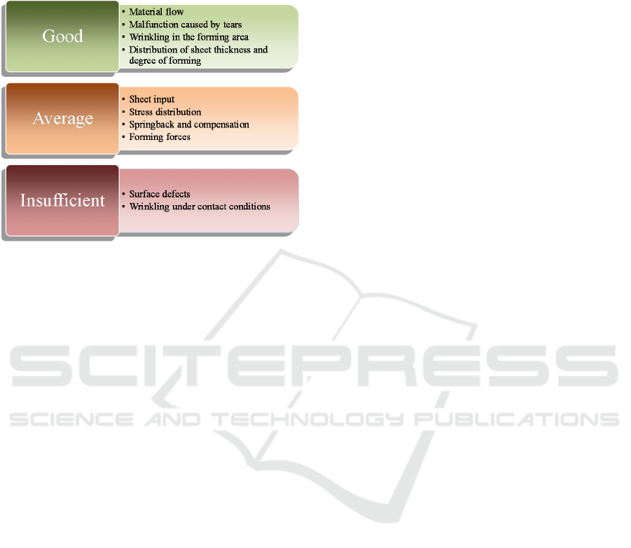
drawing processes. An overview of the forecast
capability in forming simulation is shown in
figure 1, with three groups being distinguished (Roll,
2012).
Figure 1: Forecast capability in forming simulation (Roll,
2012).
From figure 1 it becomes clear that surface
defects and wrinkles can only be detected poorly due
to the complex conditions. This is a particular
challenge for innovative technologies with extended
process kinematics. In order to fulfil the rising
demands and increase the profitability and
productivity of forming machines, at a consistent or
improved quality of drawn parts, the conventional
deep drawing process must be continuously
enhanced. An overview of deep drawing techniques
with variable motion paths is presented in
(Kriechenbauer et al., 2014). There is shown, how
superimposed low-frequency vibrations up to 50 Hz
can be a new approach to extend forming limits in
deep drawing.
One well-known example is the technology of
cushion pulsation described in (Fiat, 1994). Positive
effects of pulsating blankholder forces, like the
reduction of friction forces or the enlargement of the
gap between the wrinkling- and the fracture-border,
are described in (Doege, 2000). However, optimal
process variables of cushion pulsation could neither
temporally nor spatially be quantified in a systematic
manner yet. An approach for a cylindrical cup
through numerical simulation coupled with an
optimization technique is presented in (Kitayama et
al., 2016). The influence of process parameters from
pulsating blankholder forces on drawing depth for a
square cup is investigated in (Nezami et al. 2017).
Another example of a highly dynamic deep
drawing process is the cushion-ram pulsation on
servo-screw presses (Kriechenbauer et al., 2014).
The development of electromechanical servo-screw
presses constitutes a significant progress for deep
drawing with superimposed low-frequency
vibrations and opens new potential in sheet metal
forming. The direct driven system is characterized
by outstanding dynamical axis features, high
stiffness and the transferability of high forces. Due
to flexible controlling options, it is possible to
realize variable motion paths with ram and cushion
even in workpiece contact during forming process.
The cushion-ram pulsation extends forming limits
(Kriechenbauer et al., 2014). However, this new
approach has been investigated in an almost
exclusively phenomenological way and the design of
the process is only supported by empirical methods.
In (Neugebauer et al., 2012), progress has been
made in the simulation of low frequency vibrations
during deep-drawing processes on servo-screw
presses. New methods have been developed to
improve the predictability of process simulation by
considering the quasi-static interaction between
process and machine in (Drossel et al., 2013).
Despite the improvements, it has not yet been
possible to reproduce the component quality with
sufficient accuracy due to extensive wrinkling
phenomena.
In particular, for the simulation of the cushion-
ram pulsation, new methods have to be developed in
order to be able to predict the formation of wrinkles
more accurately and to take into account quality-
determining influences during the process
adjustment with superimposed low-frequency
vibrations. Furthermore the prognosis of optimal
process parameters is insufficient. So far there are no
corresponding assessment bases. In addition to basic
questions about process design, the root causes of
the technological effects are largely unexplained.
Fundamental research is needed in order to ensure
the prognosis accuracy of deep drawing techniques
with superimposed low-frequency vibrations on
servo-screw presses.
Consequently, the main goal of the following
paper is to give a contribution for improvements in
simulation and design of deep drawing processes
supported by vibrations, with cushion-ram pulsation
as an example. This technology is described in the
next section. Subsequently, a novel method for the
determination and assessment of single force
components is presented. This approach will be used
to enable a comparison between conventional deep
drawing, cushion pulsation as well as cushion-ram
pulsation and to understand effects and coherences
of complex forming processes. Afterwards, special
ICINCO 2018 - 15th International Conference on Informatics in Control, Automation and Robotics
622

developed test setups for experimental model tests
and preliminary results are presented. Finally a
summary and outlook of future work is provided.
2 DEEP DRAWING WITH
SUPERIMPOSED
LOW-FREQUENCY
VIBRATIONS
In the area of sheet metal forming low- as well as
high-frequency excitation mechanisms can be used
to generate different kind of vibrations. Typical
vibration amplitudes are in the millimeter range at
frequencies lower than 50 Hz (Klose and Bräunlich,
2000) and in the micrometer range at high
frequencies above 1 kHz (Siegert and Ulmer, 2001).
Usually superposition of vibrations in the tool takes
place with a magnetostrictive, piezoelectric, electro-
mechanic, or hydraulic excitation. The vibrations
favor tribological conditions between tool and sheet.
As a result the friction force is reduced. Further
positive effects of forming techniques supported by
vibrations are extended process limits, saving of
lubricant, higher drawing ratios as well as the
reduction of drawing steps and cracks (Mauermann,
2010).
Deep drawing techniques with superimposed
vibrations are highly dependent on the properties of
the forming machines used. In the past, mainly
hydraulic systems were used for this purpose.
However, modern servo-screw presses enable
vibrations in the sub millimeter range at frequencies
up to 50 Hz without additional actuators
(Kriechenbauer et al., 2014). Advantages of these
systems are high drive stiffness and dynamics as a
result of the axial powertrain arrangement. In
addition rapid changes of direction and quick load
cycles are feasible in ram as well as in cushion due
to high jerk values and great accelerations
(Neugebauer et al., 2012).
The special drawing technique on servo-screw
presses with synchronized motion paths of ram and
cushion, called cushion ram pulsation is in focus of
the investigations. This technique is a position-
controlled process with additional holding times for
the ram. The synchronized motion paths of cushion
and ram consists of sinusoidal cycles. The sequence
and corresponding parameters for an individual
cycle are illustrated in figure 2. One single cycle is
divided into two process steps. The cushion moves
away from the stationary ram during dwell time in
the first step. As a result the distance between the
sheet and the blankholder grows and the flange gap
opens. After dwell time the ram moves down to
draw the part in a small step. Due to the open flange
gap only low friction and compression forces occur
in the drawing radius and in the flange. However the
opened flange gap enables a disadvantageous
formation of wrinkles too. Subsequently in step two
the ram is stopped during the holding time and the
cushion moves against the stationary ram. That
results in an increase of surface pressure and
wrinkles in the flange will be reduced. Thereby the
cycle is completed and can be repeated as required
with possible different parameters.
During deep drawing operations, high tensile
stresses in the part frame usually lead to fractures,
which frequently occur in the punch radius. For
cushion-ram pulsation, drawing progress with
opened flange gap in the first step represents a
process similar to deep drawing without
blankholder, whereby local tensile stresses in the
frame are reduced and critical loads are shifted to
higher drawing ratios. In conventional deep drawing,
formation of wrinkles is prevented with the
blankholder and high friction forces must also be
Figure 2: Process parameters for cushion-ram pulsation (Neugebauer et al., 2012).
Root Cause Analysis of Deep Drawing Processes with Superimposed Low-Frequency Vibrations on Servo-Screw Presses - A Practical
Research on Predictability in Simulation
623
considered. As a result the total force introduced via
the punch during drawing progress is always lower
in cushion-ram pulsation than in conventional deep
drawing (Neugebauer et al., 2012). In the second
step there is no progress in drawing. Consequently
no tensile stress relevant for breakdown affects the
edge. Due to the technological separation of drawing
progress and reduction of wrinkles, larger drawing
depths can be achieved, which is a technical benefit
of the cushion-ram pulsation.
Elastic deformations of press machine and tool
systems have to be compensated by specific
parameter settings. A negative offset or die closing
force is proposed in (Neugebauer et al., 2012). The
formation of wrinkles depends on the limited ram
and cushion amplitudes. In order to achieve high
productivity it is necessary to decrease amplitudes
and to increase frequency. Usual amplitudes are
settled in the sub millimeter range.
3 NOVEL METHOD FOR THE
SEPARATION OF FORMING
FORCE
In this section, a novel method for identifying the
root causes of extended forming limits is described.
First of all, the total force required for forming is
divided into the individual terms for buckling,
bending and friction, similar to (Siebel and
Beisswänger, 1955) and (Pankin, 1961). The
necessary spatial resolution distinguishes between
flange and die radius. In both areas buckling,
bending and friction processes take place. The last
step is a time distinction for the discontinuous
processes like cushion pulsation or cushion-ram-
pulsation. A phase with low surface pressure and a
phase with high surface pressure exist there.
With the three force components for buckling,
bending and friction in the two areas of die radius
and flange for the three methods and an additional
phase I and II for cushion pulsation and cushion-ram
pulsation respectively, there are 30 individual force
components, which are summarized in table 1.
In order to determine the individual force
components, experimental and numerical tests are
planned. In this way, a better calibration of the
finite-element calculations and a fundamental evalu-
ation possibility of deep drawing with superimposed
low-frequency vibrations should be realized.
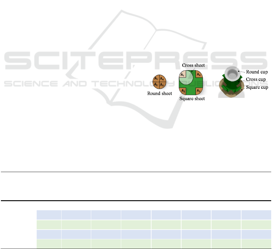
For the investigation a modular part series
illustrated in figure 3 is used. The round sheet is
virtually divided into four parts A1 to A4.
Subsequently, straight stripes are inserted, resulting
in a square sheet with round corners of a defined
radius. The inserted stripes form a cross sheet. Due
to the decomposition of the square cup, the influence
of buckling in the corner regions of the square sheet
is eliminated, thus only bending and friction forces
act. When the round cup is drawn, all three force
components take place. Together with the cross cup,
the total forming force for the square cup is
obtained. In this configuration it is possible to
examine individual force components in isolation
from each other.
Figure 3: Composition of modular part series.
To ensure that the part geometries complement
each other in a completely modular way, the
remaining geometry elements are not changed. In
addition it is necessary to observe preferably
constant and comparable boundary conditions. This
Table 1: Individual force components for deep drawing (DD), cushion pulsation (CP) and cushion-ram pulsation (CRP).
Technology Total force Kind of force
Buckling Bending Friction
Die radius Flange Die radius Flange Die radius Flange
DD F F
Bu-D
F
Bu-F
F
Be-D
F
Be-F
F
F-D
F
F-F
CP phase I F
CPI
F
CPI-Bu-D
F
CPI-Bu-F
F
CPI-Be-D
F
CPI-Be-F
F
CPI-F-D
F
CPI-F-F
phase II
F
CPII
F
CPII-Bu-D
F
CPII-Bu-F
F
CPII-Be-D
F
CPII-Be-F
F
CPII-F-D
F
CPII-F-F
CRP phase I F
CRPI
F
CRPI-Bu-D
F
CRPI-Bu-F
F
CRPI-Be-D
F
CRPI-Be-F
F
CRPI-F-D
F
CRPI-F-F
phase II F
CRPII
F
CRPII-Bu-D
F
CRPII-Bu-F
F
CRPII-Be-D
F
CRPII-Be-F
F
CRPII-F-D
F
CRPII-F-F
ICINCO 2018 - 15th International Conference on Informatics in Control, Automation and Robotics
624
means that for cushion pulsation and cushion-ram-
pulsation, suitable averages must be used as
reference values for the vibration-superimposed
process variables. Furthermore the demountability of
the square cup must be demonstrated for deep-
drawing processes with extended process kinematics
on basis of the experimentally measured force
components.
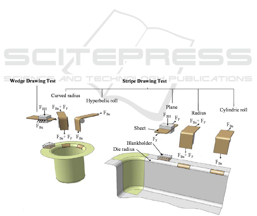
A more detailed differentiation requires addition-
al model tests, which emulate forming conditions.
Further individual force components are determined
in stripe drawing tests corresponding to (Netsch,
1994) and wedge drawing tests, which are also used
for the measurement of friction coefficients. These
model tests are illustrated in figure 4.
The friction force in the die radius is different
from those in the flange, due to different surface
pressures. Therefore the influence of friction for the
two areas is examined separately. Friction forces in
the flange are measured with the stripe drawing test
in the plane. The friction coefficient is used in the
forming simulation with finite-elements for a
corresponding material combination and normal
force. The bending forces occurring in the die radius
are determined in tests with a moveable cylindric
deflection roll. Subsequently the friction forces in
the die radius can be calculated from tests with a
fixed radius. Buckling forces can only be isolated
experimentally in the flange area, since bending also
takes place in the die radius and a metrological
resolution of the force components is not possible.
The force component in the flange may be
investigated using the wedge tensile test. In order to
recreate the conditions of the cylindrical cup the
stripe drawing tests are built with appropriately
shaped deflection roller and die radius.
However, influences from the surrounding
material areas cannot be taken into account in these
experimental model tests. Frictional losses on the
wedge surfaces also influence the result. In order to
quantify these effects, simulation models for the
stripe drawing tests with idealized boundary condi-
tions are created and validated. Force components,
which cannot be measured in experiments, must be
numerically calculated and evaluated.
4 EXPERIMENT AND
SIMULATION
In this section, first experimental and simulative
results from the conducted stripe drawing test are
presented. The experimental determination of single
force components requires the design of special test
setups. The experimental assembly for stripe and
wedge drawing tests as well as the constructed
fixture with the plane tool are illustrated in figure 5.
Figure 4: Stripe and wedge drawing tests for the determination of individual force components: left modified model tests for
the round cup, right stripe drawing tests for the square cup (Netsch, 1994).
Root Cause Analysis of Deep Drawing Processes with Superimposed Low-Frequency Vibrations on Servo-Screw Presses - A Practical
Research on Predictability in Simulation
625
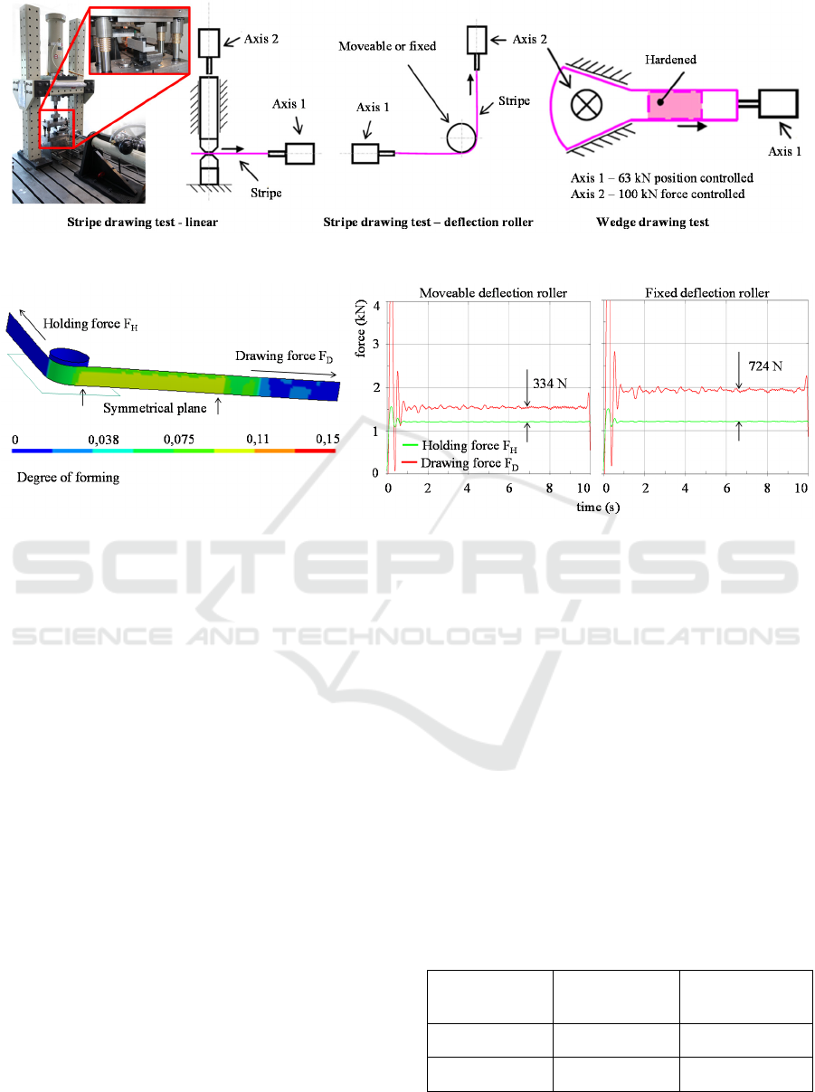
Figure 5: Experimental assembly for stripe and wedge drawing tests.
Figure 6: Simulation results from stripe drawing tests with movable and fixed deflection roller.
This setup consists of two servo-hydraulic axes.
The system enables the simultaneous and highly
dynamic control of several axes. The horizontally
arranged axis is used for the position controlled feed
while the vertically arranged axis creates the normal
forces. Force and distance measurement takes place
directly on the axes. The tool sets for different
model tests are flexible interchangeable and all tests
can be carried out in the experimental assembly. In
addition, the developed system can be used to
superimpose vibrations like in cushion pulsation and
cushion-ram-pulsation. An interrupted feed with
variable motion paths is possible, besides constant
and pulsating force transmission. Furthermore a
transition from low to high surface pressure as well
as a change between sliding and static friction when
stopping can be generated. During wedge drawing
tests the friction losses are kept as low as possible by
appropriate design and technological measures on
the wedge surfaces. This is realized by freely
rotating wheels. Here, buckling forces at the wedge
surfaces and the friction force at the blankholder are
measured.
Simulation models for the method of single force
components are set up in the first step additionally to
the experimental investigations. The models
describe the stripe drawing tests and the wedge
drawing test with finite elements. The main goal of
the simulation is to achieve a good replication of the
real experiments. Simulation results from stripe
drawing tests with movable and fixed deflection
roller for the determination of the friction and
bending forces in the radius are illustrated in
figure 6. Due to the influence of friction, the
drawing force with fixed deflection roller is higher.
A comparison between averaged values of measured
and simulated force components in preliminary
investigations of stripe drawing tests with fixed and
moveable deflection roller show good agreement
(table 2). From this it can be concluded, that the
used simulation models are suitable for recreating
experimental model tests.
Table 2: Comparison between averaged values of
measured and simulated force components for stripe
drawing tests with fixed and moveable deflection roller.
Simulation
results
Measurement
results
Deviation Δ [%]
F
Be
= 334 N F
Be
= 370 N Δ
Be
= 9.73
F
Be
+F
F
= 724 N F
Be
+F
F
= 753 N Δ
Be+F
= 3.85
ICINCO 2018 - 15th International Conference on Informatics in Control, Automation and Robotics
626
5 CONCLUSIONS
In this paper, current research results in evaluation
of simulation strategies for deep drawing processes
with superimposed low-frequency vibrations on
servo-screw presses are presented. A method for the
determination and assessment of single force
components was developed to enable a comparison
between conventional deep drawing, cushion
pulsation and cushion-ram pulsation. In addition
special test setups required for experimental
investigations as well as corresponding simulation
models were designed. A good agreement of the
results has been achieved in preliminary
investigations. The simulation models can be used to
determine further components of total deep drawing
force.
The core idea of the research project is the
evaluation and improvement of simulation strategies
for deep drawing technologies with variable motion
paths on servo-screw presses. For this reason, in the
next step, the single force components of cushion
pulsation and cushion ram pulsation have to be
investigated in experimental and numerical tests.
Subsequently experimentally determined parameters
are numerically evaluated. Then they can be used as
a boundary condition in the process simulation.
Furthermore, process parameters with low impact
have to be identified and eliminated in a sensitivity
analysis. The individual sensitivities are determined
using a DoE (Design of Experiments) method
known from statistical experimental design. The
sensitivity analysis yields a meta-model that
characterizes the relationship between the input and
output variables. This will result in an efficient
simulation model, which is quantitatively secured. In
future investigations, the individual force
components, which were not accessible in a direct
force measurement experiment or falsified by
experimental constraints, will be determined from
the validated models.
ACKNOWLEDGEMENTS
The presented results of this paper are part of a
public research project. The project (SCHL 2048/3-1
LA 3752/1-1) is financed by the research association
“Deutsche Forschungsgemeinschaft” (DFG). The
financial support is gratefully acknowledged by the
authors.
REFERENCES
Denkena, B., Hollmann, F. (2013). Process Machine
Interactions. Springer Verlag, Berlin, pp. 383-401.
Doege, E. (2000). Schwingende Niederhalterkraft
verbessert die Tiefziehergebnisse. MM -
Maschinenmarkt, 106(37), pp. 28-30
Drossel, W.-G., Müller, P., Großmann, K., Schenke, C.
(2013). Modellierung von Prozessen auf Servo-
Pressen. EFB-Report 367, Hannover.
Fiat AUTO S.p.a. Pr. (1994). Process and hydraulic press
for the pressing of sheets. EP0613740B1.
Großmann, K., Neugebauer, R. (2010).
Simulationsunterstützung für das Tiefziehen auf
Servospindelpressen. In: 30. EFB-Kolloquium:
Blechverarbeitung, Bad Boll.
Kitayama, S., Natsume, S., Yamazaki, K., Han, J., Uchida,
H. (2016). Numerical investigation and optimization
of pulsating and variable blank holder force for
identification of formability window for deep drawing
of cylindrical cup. International Journal of Advanced
Manufacturing Technology, 82(1-4), pp. 583–593
Klose, L., Bräunlich, H. (2000). Erweiterung
umformtechnischer Grenzen durch vibrations-
überlagerten Tiefziehprozess. Forschung für die
Praxis, 383, pp. 1-64.
Kriechenbauer, S., Mauermann, R., Müller, P. (2014).
Deep drawing with superimposed low-frequency
vibrations on servo-screw presses. In: Procedia
Engineering, 81, pp. 905-913.
Mauermann, R. (2010). Synchroziehen eine
Tiefziehvariante. UTFscience, 2, pp. 1-5.
Netsch, T. (1994). Methoden zur Ermittlung von
Reibmodellen für die Blechumformung. PhD thesis,
Technische Universität Darmstadt.
Neugebauer, R., Drossel, W.-G., Kriechenbauer, S.
(2012). Erweiterung der Umformgrenzen mit Direkt-
Servo-Spindelpressen. EFB-Report 354, Hannover.
Nezami, S., Akbari, A., Ahangar, S. (2017). Parametric
investigation of pulsating blank holder’s effect in deep
drawing process of rectangular Al 1050 Cup. Journal
of the Brazilian Society of Mechanical Sciences and
Engineering, 39(10), pp. 4081-4090
Pankin, W. (1961). Die Grundlagen des Tiefziehens im
Anschlag unter besonderer Berücksichtigung der
Tiefziehprüfung. Bänder Blech Rohre, 4, pp. 133-143.
Roll, K. (2012). Sheet metal forming simulation for
automotive applications. In: Deutsch-französische
Sommerschule: Verfestigung und Schädigung von
Metallwerkstoffen unter großen Dehnungen –
Konstitutive Modellierung und numerische
Implementierung, Dortmund.
Siebel, E., Beisswänger, H. (1955). Tiefziehen. Hanser
Verlag, München.
Siegert, K., Ulmer, J. (2001). Influencing the Friction in
Metal Forming Processes by Superimposing
Ultrasonic Waves. In: CIRP Annals - Manufacturing
Technology, 50(1), pp. 195-200.
Root Cause Analysis of Deep Drawing Processes with Superimposed Low-Frequency Vibrations on Servo-Screw Presses - A Practical
Research on Predictability in Simulation
627
