
A Refactoring Architecture for Measuring and Identifying Spots of
Design Patterns Insertion in Source Code
Luan Bukowitz Beluzzo, Simone Nasser Matos and Thyago Henrique Pacher
UTFPR, Ponta Grossa, Parana, Brazil
Keywords:
Software Architecture, Refactoring, Design Patterns.
Abstract:
This work presents an architecture for detecting insertion spots of design patterns in an object-oriented source
code. The proposed architecture contains a Service that implements Detection Methods (DMS) present in the
literature such as identification of precursors, prolog rules and facts, among others. The DMS notifies the
Metrics Service (MS) which patterns can be used. The evaluation of the application of the patterns undertaken
by the MS is performed by means of quality metrics such as maintainability, flexibility, and so forth. The
MS notifies the Client App (CA) of the advantages and disadvantages of using the eligible patterns. The CA
interacts with the user to retrieve decisions about which changes to perform in source code according to the
design pattern real benefit and notifies the Applier Service (AS), that applies the patterns in the source code.
The difference between the proposed architecture and the literature is that it allows a thorough interaction with
the user and it creates an extendable environment to cover several pattern detection/insertion methods. The
architecture allows automated support to users engaged in the refactoring process based on design patterns.
1 INTRODUCTION
Refactoring processes correct bad smells or code that
is poorly written. These processes are aimed to pro-
vide a good internal structure for a software project,
to remove duplicated code, find meaningful names for
methods and classes, restructure class hierarchies and
others (Fowler and Beck, 1999). Some quality requi-
rements such as performance, maintainability, loose
coupling, high cohesion and reusability can be impro-
ved in a software project through refactoring (Fowler
and Beck, 1999; Mens and Tourw
´
e, 2004).
Design patterns may be attached to refactoring
processes improving code flexibility, these patterns
are highly recommended during software natural evo-
lution (Cinneide, 2000). The benefits of applying
these patterns are widely known, being present in
works that detect them, like the ones of Chatzigeor-
giou et. al (Chatzigeorgiou et al., 2006) and Li et.
al (Li et al., 2007), as well as in works that used them
within refactoring processes such as Christopoulou et.
al (Christopoulou et al., 2012), Zafeiris et. al (Zafeiris
et al., 2017) and Zanoni et. al (Zanoni et al., 2015).
It has been a more common approach to deal
with refactorings to patterns in an automated man-
ner (Christopoulou et al., 2012; Fontana and Zanoni,
2011; Zafeiris et al., 2017).
This work proposes an architecture aimed to pro-
vide a structure that covers methods in the literature
that identify spots to insert design patterns in source
code, also, some other methods that apply these pat-
terns in a given project. Besides detecting and inser-
ting patterns in source code, this architecture will also
be responsible for the evaluations of the possible re-
factorings and to promote interactions with the user,
providing feedbacks and relying on his/her decisions
to actually execute the proposed procedures.
2 BACKGROUND WORKS
In order to extend the reader’s perception concerning
methods that to introduce design patterns in source
code, the following descriptions present a deeper un-
derstanding of some methods of the literature.
Some works were analyzed during the develop-
ment of the architecture, these were gathered consi-
dering the past twenty years. Cinn
´
eide and Nixon
(Cinn
´
eide and Nixon, 1999) for example, created a
method to insert a given design pattern based on mi-
nipatterns and minitransformations.
Jeon, Lee and Bae (Jeon et al., 2002) only pro-
pose a method to identify spots to insert design pat-
terns in code through prolog rules and facts; Gaitani
632
Beluzzo, L., Matos, S. and Pacher, T.
A Refactoring Architecture for Measuring and Identifying Spots of Design Patterns Insertion in Source Code.
DOI: 10.5220/0006868006320639
In Proceedings of the 13th International Conference on Software Technologies (ICSOFT 2018), pages 632-639
ISBN: 978-989-758-320-9
Copyright © 2018 by SCITEPRESS – Science and Technology Publications, Lda. All rights reserved
et al. (Gaitani et al., 2015) propose refatorings to-
wards a NULL Object design pattern; Christopoulou
et al. (Christopoulou et al., 2012) identify the spots to
insert a Strategy design pattern, these are spots con-
taining conditional statements with two or more bran-
ches.
Analyzing the works Cinn
´
eide and Nixon
(Cinn
´
eide and Nixon, 1999), Jeon, Lee and Bae
(Jeon et al., 2002), Gaitani et al. (Gaitani et al.,
2015) and Christopoulou et al. (Christopoulou et al.,
2012), it is noticed that features could be added to
their process, for example, measuring whether the
insertion brings actual benefits to the project and
improving interactions with the user.
Considering the above mentioned and the other
works of the literature that were studied, this ar-
chitecture focuses on having more interactions with
the user. It also evaluates the refactoring possibility
through software metrics. As last, it provides an en-
vironment that covers several refactoring methods of
the literature, which enables the user to use an unique
process (having no need to search for other refacto-
ring tools).
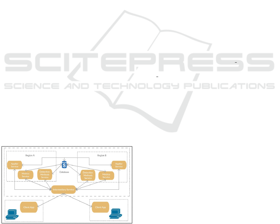
3 PROPOSED ARCHITECTURE
The proposed architecture (Figure 1), called Ar-
chProMe, is composed of tree core modules: Applier
Service (AS), Metrics Service (MS) and Detection
Methods Service (DMS); an intermediary one called
Intermediary Service (IS) and a Client App (CA).
The modules that present this name Service are the
ones that contain the pattern Service Layer, this pat-
tern presents some functionalities that are made avai-
lable to external users, like a boundary that encapsu-
lates business rules and control the responses to be
given in each functionality (Fowler, 2002).
Figure 1: Architecture Overview.
The CA in turn, promotes the interaction between
the users of the architecture (probably software deve-
lopers) and is responsible for communicating with the
IS in order to request operations from the core.
It is quite noticeable that Figure 1 displays a dupli-
cated structure in the architecture, the only difference
being the identifier of the so called Regions (A and B).
These regions were built considering the possibility to
have absent modules in each region, it also provides
means to distribute the requests from the CAs to the
alive members in the core.
The main idea is that each member of the Region
must send messages directly to the IS, this confirms its
alive state within the architecture. After that, once the
IS receives a request from a given CA, it can redirect
the call to a specific member for processing.
Once the overview of the architecture is well sta-
blished, the following sections are in charge of having
a detailed description of the basic requirements of the
architecture and afterwards, the internal procedures of
each module.
3.1 Architecture Inputs
The input corresponds to a project with a set of
subsystems, at the lowest level of each subsystem is a
set of source files.
Within the project, a Project Description file is
provided so that the project may be registered. The
Project Description has the project id (empty at first
and filled by a procedure of the architecture), pro-
ject name (significant name given by the project ow-
ner) and a source code folder path (src).
A .prop extension is placed with the project file
name as a markup extension to be read by the CA,
which identifies the text file as a Project Description.
The first requirement of the ArchProMe is to know
in depth the methods of the literature focused on
the insertion and detection of patterns insertion spots
(Section 2). In case of the creation of a new method,
the architecture must be prepared to be extended.
The second requirement for the ArchProMe are a
set of metrics, which are used to evaluate the qua-
lity of the source code. These metrics provide means
to precisely measure a source code through quantita-
tive values. They also contribute to measure quality
requirements such as: reliability, maintainability and
others.
After having the base for the refactoring (require-
ments) and receiving the input value (project), the ar-
chitecture is ready to detect what design patterns can
be inserted within the source code.
3.2 Client App
This module presents two main responsibilities: to in-
teract with the user and to communicate with the IS.
A Refactoring Architecture for Measuring and Identifying Spots of Design Patterns Insertion in Source Code
633

Among the interactions with the user, it is expected to
extract data inputs from the user and present some in-
formation from the architecture core (patterns eligible
for insertion and metrics analysis result).
There are two main interactions available for the
user: start process and apply patterns:
Start Process: This interaction is triggered by the
user and it causes the CA to request two operations
provided by the IS. First the CA is responsible for col-
lecting project data from the Project Description, after
that, the CA requests the IS to register the project at
hand. The source code is compressed and sent with
all the other data collected initially.
After registering the project, the CA executes a
new request, this time it actually starts the refactoring
process. Now the CA has the id of the registered pro-
ject and uses it to make this start refactoring request.
At the end of this call, the CA receives all patterns eli-
gible for applying in the source code along with their
improvements in quality attributes terms.
Apply Patterns: Once the CA has all patterns eligi-
ble for applying in the source code, it displays them
to the user, along with their quality attributes evalua-
tion (detailed in the MS flow), so that s/he may choose
which to apply in his/her source code.
The CA retrieves the user’s choices and is in
charge of sending this data to the IS, this data is pro-
cessed to alter the source code. Once the refactored
source code is created, the CA displays a last mes-
sage, confirming the refactoring with the user.
If the user decides not to apply the chosen pat-
terns, either because s/he has given up or because s/he
decided that the refactorings do not worth to be exe-
cuted, then the refactoring process is cancelled. If
the user agrees that the refactorings should be made
the activities of the user are frozen and the old source
code is replaced by the new one (the refactored one).
3.3 Intermediary Service
All modules of the architecture do not communicate
with each other directly, the requests/responses are
sent to the the IS which in turn has the responsibi-
lity to manage these interactions between the modu-
les. This Service has to deal with the source code
inputs arriving from the CA as well.
In order to manage the active modules of the ar-
chitecture (Figure 1), these are grouped by their type,
that is, DMSs with DMSs, MSs with MSs and ASs with
ASs; in such a way, that for every type, there is a queue
related to it.
As already mentioned, a member is taken as active
if it frequently sends alive messages to the IS. This
kind of control is useful when a new request is re-
ceived and to distinguish what architecture member
should be executed, the IS searches in its queues by
type, the Service to be called.
For every kind of request received by the IS, the
due Service is retrieved from its own queue and called
through an HTTP request for processing.The functio-
nalities of this module, as well as the Services called
in the requests are presented as follows:
Register Project Request: It inserts the source code
(along with the other data provided) in the database.
The project will have its unique id once it is inserted,
after that, the id is sent as a response.
Start Refactoring Request: It retrieves the first DMS
in the queue and requests a pattern insertion spots
evaluation (with the id of the project). At the end of
the execution, the DMS receives as a reply all patterns
eligible for application, it forwards it to the IS along
with the id of the project.
Source Code Evaluation Request: it retrieves the
first MS available in the queue and forwards the evalu-
ation request to it (along with the id of the project and
the patterns eligible for application). After receiving
the response of the module, the IS sends a response
message to the CA with the eligible patterns and their
quality evaluations.
Pattern Insertion Request: This insertion is only
ment to refactor the source code based on one pattern
alone. As expected, the first DMS is retrieved from
the queue and, the application of a given pattern P1,
of a refactoring method M2, in the source code with
id XYZ is requested.
The response of this call is the id of the refactored
source code, this is because after the refactoring of
DMS, the refactored code is compressed and inserted
in the database of the architecture.
Source Code Refactoring Request: In this stage, the
patterns for the final refactoring were already chosen
by the user. The AS from the queue is retrieved and
is responsible for managing the application of all se-
lected patterns. The source code containing all the
patterns selected by the user is send to the CA. At last,
the project source code is removed from the database.
3.4 Detection Methods Service
One of the functions executed by this Service is to
check which patterns can be applied in the source
code. This module receives the request and submits
the source code to the evaluation of refactoring met-
hods present in the literature.
The refactoring methods of the literature have dis-
tinct approaches as to how to detect patterns insertion
spots in a certain source code. Gaitani et al. (Gaitani
et al., 2015) converts the source to Abstract Syntax
ICSOFT 2018 - 13th International Conference on Software Technologies
634
Trees (Jones, 2003) to check the possibility to insert
the Null Object pattern; also, Rajesh and Janakiram
(Rajesh and Janakiram, 2004) convert a source code
in Prolog Facts (Clocksin and Mellish, 2003), in or-
der to search for insertion spots through Prolog Rules.
This kind of perception was only possible due to the
analysis of the works of the literature in Section 2.
Considering these possibilities, the evaluation of
insertion spots in the source code was fragmented into
data extraction approaches, this happened to avoid du-
plications since several methods have the same ex-
traction approach; after that, each method is executed.
The methods themselves are the ones found in the
literature (Section 2). In case of a new source code
extraction approach which cannot be detached from
its own refactoring method, then it will not be placed
along with the generic approaches.
Figure 2: Detection Methods Service - Gaitani et al. (Gai-
tani et al., 2015) Method Execution.
Figure 2 state shows an example of a possible in-
sertion spot for the Null Object pattern using the met-
hod provided by Gaitani et al. (Gaitani et al., 2015).
The highlighted parts (on the left) represent the spots
that can be altered; the object buyer, instead of being
instantiated with a null value can have a default in-
stance (Null Object) and the conditionals checking for
null values are discarded.
Figure 3: Detection Methods Service - Liu et al. (Liu et al.,
2014) Method Execution.
An example of the detection of the Factory Met-
hod pattern (Figure 3) is proposed by Liu et al. (Liu
et al., 2014), that demonstrates a complex conditional
expression evaluating the values of the type variable.
This conditional expression can be replaced by a Fac-
tory Method or a Strategy pattern depending on whet-
her the conditional expression creates a new object or
not. In this example, the internal procedures of each
branch of the conditional statement is replaced by a
child of the Factory Method base class.
Another method that applies a Strategy pattern, is
the work of Christopoulou et al. (Christopoulou et al.,
2012), that also looks for conditional statements to
insert the pattern. Figure 4 shows an example of a
class eligible for refactoring.
Figure 4: Detection Methods Service -Christopoulou et al.
(Christopoulou et al., 2012) Insertion Spot.
Considering the three previous methods, it can be
seen that the patterns eligible for application are: Null
Object, Factory Method and Strategy. Of course, the
idea is that not only the refactoring methods presented
here can be part of the architecture, that is why they
have a common input (id of the project pending of
evaluation), a data extraction approach (if it is pos-
sible to detach it from the method) and a common
output (a set of methods and their respective patterns
eligible for application).
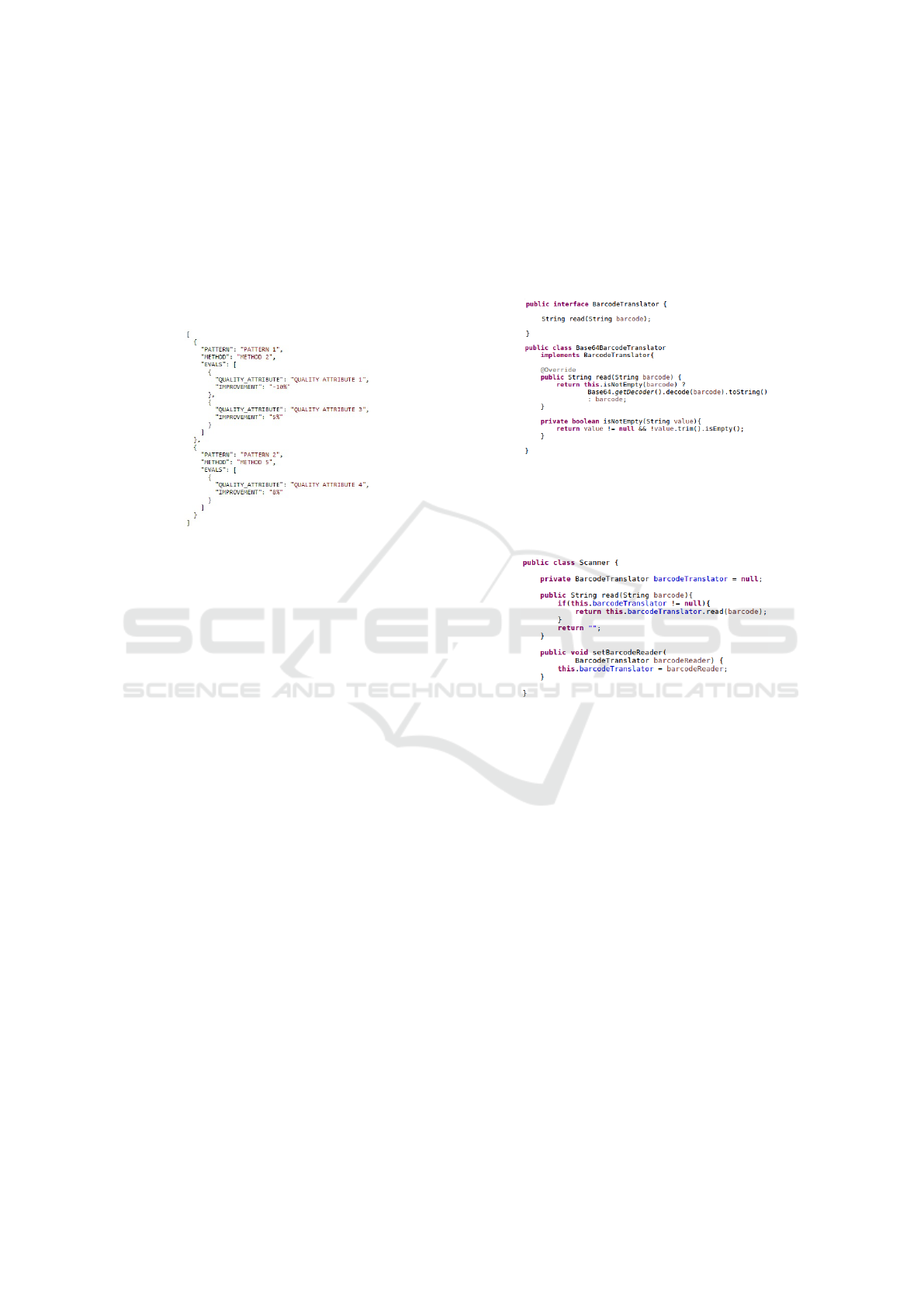
The DMS receives the return of the refactoring
methods and it groups them to a single response. Fi-
gure 5 presents it in a generic response.
If a method M1 elects a Factory pattern to be inser-
ted in the source code, and another method M2 elects
the same possibility, then, the architecture is respon-
sible for ignoring one of the possibilities.
Besides detecting patterns insertion spots, this ser-
vice is also responsible for refactoring a certain source
code through an insertion request. Once the IS reque-
A Refactoring Architecture for Measuring and Identifying Spots of Design Patterns Insertion in Source Code
635
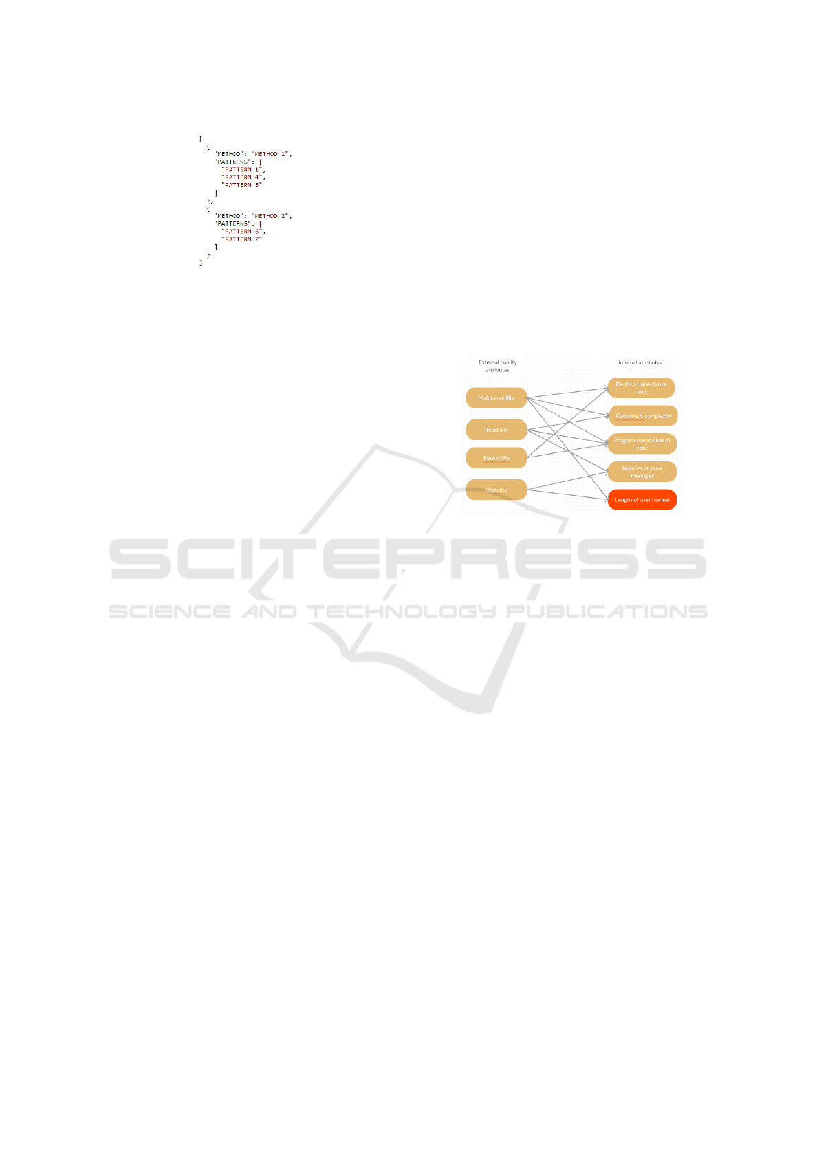
Figure 5: Detection Methods Service - Generic Response.
sts the application of a pattern, it will send what was
the method used for detecting the insertion spots al-
ong with the pattern authorized for insertion.
In its internal execution, the DMS must have a cor-
relation between a method that detects patterns inser-
tion spots and the method which will undertake the
refactoring for that given pattern. The work of Jeon,
Lee and Bae (Jeon et al., 2002) for example, only de-
tects insertion spots for design patterns through Pro-
log Facts, however, when it has the insertion spots, the
method of Cinneide and Nixon (Cinn
´
eide and Nixon,
1999) is used to refactor the source code.
Finally, the source code is refactored through a
similar process as the one to detect insertion spots,
first transforming the code into extraction approaches,
then, actually refactoring the code. The refactored
source code, with all eligible patterns applied, is then
compressed and inserted in the database of the archi-
tecture. The id of this new record is then sent as re-
sponse of the operation.
3.5 METRICS SERVICE
The MS module was conceived in the architecture so
that the user may have objective values for perceiving
the actual benefits of the refactoring (in terms of soft-
ware quality metrics) once a certain pattern is applied.
The evaluation of the improvement is executed with
the patterns eligible for applying, the ones retrieved
through the execution of the DMS.
The evaluation of the source is initialized once it
is requested to the IS, this process searches the pro-
ject’s original source code (through its id) and measu-
res it extracting metrics about the class, inheritance,
methods, system and coupling. The result of this first
evaluation is called OPM (Original Project Metrics),
that will be used further on.
The first elected pattern is selected and its inser-
tion is requested, this request is sent to the IS for due
processing. The MS retrieves the refactored source
code through the id received as response from the in-
sertion process. This code is then submitted to the
same evaluation of the original source code, in order
to get the RPM (Refactored Project Metrics).
When comparing the OPM with the RPM, there
can be some unchanged metrics, nevertheless, only
those presenting differences between versions will be
used in the evaluation. The first elected pattern was
used as an example, but the the same evaluation is
going to be performed for all elected patterns.
The final evaluation uses correlations between
Metrics and Quality Attributes so as to compose its
response. Sommerville (Sommerville, 2011) associ-
ates quality attributes with five software metrics (Fi-
gure 6). This association is used in the architecture
in order to retrieve values of quality attribute from the
measurement between (OPMs and RPMs) and send
these attributes to the user.
Figure 6: Quality Attributes x Metrics (Sommerville, 2011).
Among the metrics of Figure 6, only length of user
manual will not be used (that is why it is highlighted),
because the architecture is structured only to evaluate
the source code, and not its manual.
If we look at the example of Figure 6, the metrics
will be evaluated according to their index (i), being
the first index (0) depth of inheritance tree, cycloma-
tic complexity is the element on index 1 and so forth.
The equation 1 will be used for metrics of the original
project (M i OP) as well as for the refactored one (M
i PR).
MP
i
= ((M
i
PR ∗ 100)/M
i
PO) − 100 (1)
Considering all metrics involved in a quality attri-
bute, an arithmetic mean is calculate with these per-
centage values (according to Equation 2), in which
n is the index of the metric (n representing the last
possible value for this index) and where m is the to-
tal of metrics associated with that quality attribute.
The final result is this final percentage of impro-
vement/decline of the quality attribute.
QA
qai
= (MP
0
+ MP
1
+ ...MP
n
)/m (2)
In order to calculate the quality attribute reusabi-
lity, with the quality attribute index (qai) 2, there are
two metrics involved in this process: depth of inheri-
tance tree (index 0) and program size in lines of code
(index 2). With these values at hand, the resulting
ICSOFT 2018 - 13th International Conference on Software Technologies
636
formula for this quality index is presented as follows
(Equation 3).
QA
2
= (MP
0
+ MP
2
)/2 (3)
In the example of Figure 7, it is presented the
expected response from this Service, with the eva-
luation of two patterns (and their related refactoring
methods). As predicted, each quality attribute (Fi-
gure 6) is returned with its percentage of impro-
vement/decline.
Figure 7: Metrics Service - Generic Response.
The MS is then responsible for retrieving the re-
sults from all evaluations of the patterns and group
them in order to send a final result to the IS, which
will forward the results to the CA for the last decision.
3.6 Applier Service
This module has at hand the patterns selected (by the
user) for application. Since the user has at his/her
disposal several patterns to be selected, s/he chooses
what patterns to apply in the source code based on the
provided quality attributes.
The CA sends the apply patterns request to the IS,
which forwards the request to the AS. For every se-
lected pattern, the AS will request to the IS to insert
the pattern in the source code. If no refactor has been
made yet, then this module retrieves the id of the ori-
ginal source code for the first request; however, as for
the other refactorings, the id returned from the refac-
toring process is going to be used for the next request.
After the refactorings, the id of the refactored
source code is sent to the IS marking the end of the
process for this module.
3.7 Applying the Architecture
Suppose an application that applies the three pattern
detection/insertion methods presented in Subsection
3.4. As an input example, let’s imagine a barcode
scanner device that supports an inner barcode trans-
lator that can be changed at will.
This kind of situation might be useful in cases
when the barcode has a specific encryption or pattern
that could be read and changed into inteligible data.
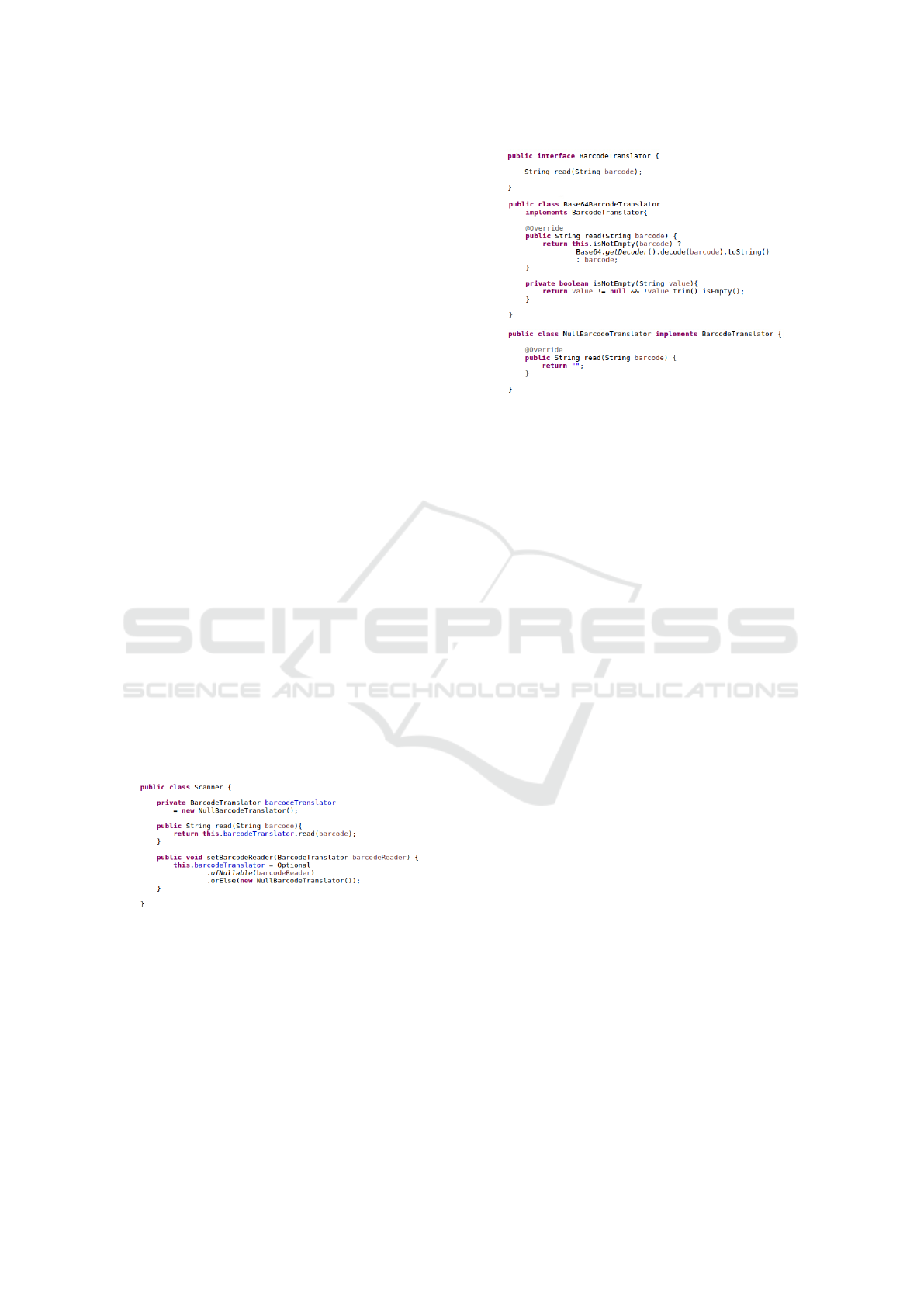
The sample code was developed using Java, and
for this very example, two classes and one in-
terface were created: BarcodeTranslator interface,
Base64BarcodeTranslator class (Figure 8) and finally
a Scanner.java class.
Figure 8: Barcode Translator Hierarchy - Before.
The first two Java files representing the muta-
ble inner translation mechanism and the Scanner.java
class representing the device itself (Figure 9).
Figure 9: Scanner class - Before.
The reader may notice that each following request
example is based on the functionalities of the CA, so
it will become clearer what is expected in the back-
ground of each function triggered by the user.
Each module of the architecture core is a distinct
Service, then each request is built upon (has is functi-
ons available) over the HTTP protocol.
The registration of the project is a POST call to the
IS, which will send the description of the project and
its source code as well. Once the project is registered,
its id is sent to the CA as a response.
The CA will make a POST call to the IS once
more, this time sending the only the id of the project
with the start refactoring request. The DMS, when
called by the IS, collects all eligible patterns and sends
them back to the IS for evaluation. This last call for
evaluation is then forwarded to the MS for individual
evaluation of the patterns.
The only pattern eligible for application in this
example was Null Object. This is because the code
under evaluation (Figures 8 and 9) does not present
complex conditional statements, which are the base
A Refactoring Architecture for Measuring and Identifying Spots of Design Patterns Insertion in Source Code
637
preconditions for the methods of Liu et al. (Liu et al.,
2014) and Christopoulou et al. (Christopoulou et al.,
2012); also, the null initialization of the Barcode-
Translator and the null check in the read method (Fi-
gure 9) are both signs of an insertion spot in the met-
hod proposed by Gaitani et al. (Gaitani et al., 2015).
After applying the pattern in the source code, the
only two metrics that did not remain the same were
Program size in lines of code and Cyclomatic com-
plexity. These metrics increased in 18% (from 28 to
33) and 11% (from 10 to 11) respectively. They were
used to evaluate quality attributes through Equation 2.
Although the evaluation presents no great benefits
from the application of the refactoring, the user may
still want to apply this code because s/he will not need
to deal with null instances of BarcodeTranslator.
It can be noticed that some parts of the process
were omitted during its explanation, this is because
they were covered in depth in previous sections.
In the second part of the refactoring, the DMS will
apply the patterns once again. The only difference is
that, the service will change the same project under
refactoring, creating a single result source code with
all the patterns selected for application. In this case,
the user only had Null Object pattern as an option.
As expected of the method of Gaitani et al. (Gai-
tani et al., 2015), it is created a new class for a gi-
ven class hierarchy, this Null class represents a de-
fault behavior for its null instances. That is why when
this method is applied over the given source code, the
Null class of BarcodeTranslator is set as the default
instance for the inner variable of Scanner; also, when
a new value for this variable is set, it is first checked
if it is null, if it is, then the default instance replaces
the null value in it (Figure 10).
Figure 10: Scanner class - After.
Figure 11 presents the new hierarchy of the Bar-
codeTranslator interface, with the new NullBarcode-
Translator.
After the refactoring, the new code is sent as a
HTTP response for the applyPatterns request.
As observed, using the proposed architecture the
user has more possibilities of refactorings in the
source code, and a deep evaluation of the source code
in order to aid the user when choosing which patterns
to apply. So if one method cannot be applied or is not
Figure 11: Barcode Translator Hierarchy - After.
available, the architecture still has other possibilities.
4 CONCLUSIONS
This paper proposed an architecture that detects pat-
terns insertion spots and patterns insertion in midst
of a given source-code, for this matter it is based on
methods of the literature to define its execution.
The main idea is that a certain code or project goes
through the processes of: using literature methods to
identify insertion spots of patterns; being evaluated,
providing patterns information to clients that deter-
mine which of them they want to apply; evaluating the
source code it in terms of quality requirements using
software metrics; applying the patterns desired by the
client.
As additional future works, more implementations
of the architecture can be developed, providing broa-
der test scenarios. Also, when choosing what met-
hods should remain in the process to retrieve eligi-
ble patterns (found in Section 3.4), a more intelligent
approach (considering the most effective refactoring
methods, for example) could be implemented.
REFERENCES
Chatzigeorgiou, A., Stephanides, G., Tsantalis, N., Halki-
dis, S., et al. (2006). Design pattern detection using
similarity scoring.
Christopoulou, A., Giakoumakis, E. A., Zafeiris, V. E.,
and Soukara, V. (2012). Automated refactoring to
the strategy design pattern. Information and Software
Technology, 54(11):1202–1214.
Cinneide, M. O. (2000). Automated refactoring to introduce
design patterns. In Proceedings of the 22nd internati-
onal conference on Software engineering, pages 722–
724. ACM.
ICSOFT 2018 - 13th International Conference on Software Technologies
638

Cinn
´
eide, M.
´
O. and Nixon, P. (1999). A methodology
for the automated introduction of design patterns. In
Software Maintenance, 1999.(ICSM’99) Proceedings.
IEEE International Conference on, pages 463–472.
IEEE.
Clocksin, W. F. and Mellish, C. S. (2003). Programming in
PROLOG. Springer Science & Business Media.
Fontana, F. A. and Zanoni, M. (2011). A tool for de-
sign pattern detection and software architecture recon-
struction. Information sciences, 181(7):1306–1324.
Fowler, M. (2002). Patterns of enterprise application ar-
chitecture. Addison-Wesley Longman Publishing Co.,
Inc.
Fowler, M. and Beck, K. (1999). Refactoring: improving
the design of existing code. Addison-Wesley Professi-
onal.
Gaitani, M. A. G., Zafeiris, V. E., Diamantidis, N., and Gia-
koumakis, E. A. (2015). Automated refactoring to the
null object design pattern. Information and Software
Technology, 59:33–52.
Jeon, S.-U., Lee, J.-S., and Bae, D.-H. (2002). An automa-
ted refactoring approach to design pattern-based pro-
gram transformations in java programs. In Software
Engineering Conference, 2002. Ninth Asia-Pacific,
pages 337–345. IEEE.
Jones, J. (2003). Abstract syntax tree implementation idi-
oms. In Proceedings of the 10th conference on pattern
languages of programs (plop2003), page 26.
Li, F., Li, Q.-s., Su, Y., and Chen, P. (2007). Detection of
design patterns by combining static and dynamic ana-
lyses. Journal of Shanghai University (English Edi-
tion), 11(2):156–162.
Liu, W., Hu, Z.-g., Liu, H.-t., and Yang, L. (2014). Automa-
ted pattern-directed refactoring for complex conditio-
nal statements. Journal of Central South University,
21(5):1935–1945.
Mens, T. and Tourw
´
e, T. (2004). A survey of software refac-
toring. IEEE Transactions on software engineering,
30(2):126–139.
Rajesh, J. and Janakiram, D. (2004). Jiad: a tool to infer
design patterns in refactoring. In Proceedings of the
6th ACM SIGPLAN international conference on Prin-
ciples and practice of declarative programming, pages
227–237. ACM.
Sommerville, I. (2011). Software Engineering. Pearson
Higher Education.
Zafeiris, V. E., Poulias, S. H., Diamantidis, N., and Gia-
koumakis, E. (2017). Automated refactoring of super-
class method invocations to the template method de-
sign pattern. Information and Software Technology,
82:19–35.
Zanoni, M., Fontana, F. A., and Stella, F. (2015). On ap-
plying machine learning techniques for design pattern
detection. Journal of Systems and Software, 103:102–
117.
A Refactoring Architecture for Measuring and Identifying Spots of Design Patterns Insertion in Source Code
639
