
Development of a Ground Truth Localization System for Wheeled
Mobile Robots in Indoor Environments based on Laser Range-finder for
Low-cost Systems
Luis Piardi
1
, Jos
´
e Lima
2,3
and Paulo Costa
3,4
1
Federal University of Technology, Paran
´
a, Toledo, Brazil
2
Research Centre in Digitalization and Intelligent Robotics (CeDRI), Instituto Polit
´
ecnico de Braganc¸a, Portugal
3
INESC-TEC, Centre for Robotics in Industry and Intelligent Systems, Porto, Portugal
4
Faculty of Engineering of University of Porto, Porto, Portugal
Keywords:
Robot Localization, Lidar, Ground Truth, Circular Fitting.
Abstract:
The localization systems are becoming more and more required in the actual flexible manufacturing systems
based on mobile robots. There are several approaches to localize a mobile robot such as laser scanners reflec-
tive beacons, image mapping, lightning based systems, Ultra-wideband time-of-flight trilateration, odometry
and fusion sensor data algorithms. During the development phase of a localization methodology, it is nec-
essary to evaluate the proposed system: it is used a ground truth system. Ground truth systems are precise
(usually based on reflective beacons) but expensive. This paper presents a low-cost ground truth system based
on a standard low-cost laser scanner that, coupled with the presented algorithm, allows to localize the robot
in the field and thus evaluate other localization systems. Results of the precision of the developed system are
presented and validates the approach.
1 INTRODUCTION
Nowadays, constant advances and several relevant ap-
plications have been emerging in the field of mobile
agents in indoor environments. A great example is
the autonomous mobile robots area. Thus, one of the
main research areas employs efforts in the develop-
ment of hardware and techniques such as Kalman and
Particle filter to optimize the localization of these mo-
bile agents, dealing with the complex minimization of
errors and uncertainties due to noise.
Consequently, different methods are applied in the
difficult task of locating mobile agents in internal en-
vironments, having different levels of precision and
costs. The most common technologies are:
Wi-Fi with an accuracy of 1-3 m (Zhong et al., 2016),
bluetooth with an accuracy of 0.5 - 1 m (Rida et al.,
2015) and Ultra Wide Band (UWB) (Lima and Costa,
2017) with an accuracy of 0.1 - 0.3 m. Methods
based on data processing of cameras and Laser Range
Finder (LRF) are also applied, however they have a
higher price compared to the technologies previously
mentioned.
The main contribution of this article is a proposal
of a low-cost ground-truth system, based on a popular
LRF, for evaluation of one other localization system
under development. It can be used in one indoor mo-
bile robot localization system and it will localize one
object with a circular geometric shape within its line
of sight. This object is easily coupled to the mobile
agent.
An outline of this paper is as follows. In Sec-
tion 2 the state of the art of the main applications
with LRF is presented. In Section 3 the methodology
with the description of the sensor and the object is ad-
dressed, besides presenting the calculations involved
in the proposed approach. Experimental results are
presented in Section 4 and Section 5 concludes the
paper.
2 RELATED WORK
Currently the laser-based scanner technology has pro-
vided the ability to develop applications for precise
and fast non-contact measurement in a wide range of
applications.
The laser range finder is applied for 2D mapping
Piardi, L., Lima, J. and Costa, P.
Development of a Ground Truth Localization System for Wheeled Mobile Robots in Indoor Environments based on Laser Range-finder for Low-cost Systems.
DOI: 10.5220/0006862203410348
In Proceedings of the 15th International Conference on Informatics in Control, Automation and Robotics (ICINCO 2018) - Volume 2, pages 341-348
ISBN: 978-989-758-321-6
Copyright © 2018 by SCITEPRESS – Science and Technology Publications, Lda. All rights reserved
341
(i.e., a laser that scans in one plane) and 3D mapping
(i.e., a laser that scans and “nods” thus producing a
range image of an area) (Okubo et al., 2009). In the
present work it will be focused on the application of
laser in 2D scan once it is computationally more effi-
cient in the process of tracking an object.
In the last decade the LRF with 2D scanning was
applied in several activities in mobile robotics, such
as detecting and avoiding collision with obstacles. In
(Xu et al., 2006), was proposed a method for obstacle
detection based on stochastic density of scan points
using a robot equipped with a laser scanner in struc-
tural or semi/non-structural environment. Another ex-
ample is the paper (Zeng and Weng, 2007) where a
mobile humanoid robot is equipped with a 2D laser
scanner to detect and avoid static and dynamic obsta-
cles through on-line real-time incremental learning.
The 2D Laser Range Finder is also widely applied
for the construction of maps in a single slice of the
plan (Nepali et al., 2015; Olson, 2015). In (Nepali
et al., 2015) the LRF data are used together with seg-
mentation algorithm methods, Split and Marge algo-
rithm and best algorithm for reconstruct floor plans
with centimeter precision. However, these techniques
accumulate errors and have a considerable computa-
tional cost (Hess et al., 2016).
In this same context, the LRF has been amply used
in simultaneous localization and mapping (SLAM)
problem. SLAM addresses the problem of robot nav-
igation in an unknown environment (Siciliano and
Khatib, 2008; Santos et al., 2013). In (Sobreira et al.,
2015) was used a security laser presented on most of
industrial AGVs for traveling in the unknown envi-
ronment, while generating the map and at the same
time it wishes to localize itself using its map.
More related to this work is the use of an exter-
nal and fixed LRF to perform the tracking of cylin-
drical objects attached to moving devices such as mo-
bile robot. Teixid
´
o et al. (Teixid
´
o et al., 2012) com-
bined the information obtained from an external fixed
LRF with algorithm for outlier avoidance and a least-
squares circular fitting to detect cylindrical targets at-
tached to moving devices (Teixid
´
o et al., 2012).
Given the wide range of applications of the LRF
and the wide acceptance of academia and industry in
its use, the present work will be composed by a laser
scanner to perform mobile robot tracking in internal
environments, i.e. a ground truth to validate low cost
localization systems based on other emerging tech-
nologies such as Ultra Wide Band.
3 METHODOLOGY
This section, will present the methods and materials
used in this work for the development of the ground
truth system to track a circular object.
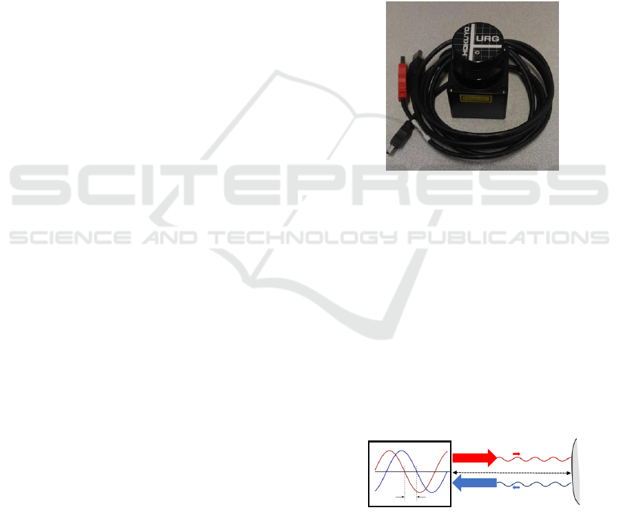
3.1 Hokuyo Sensor Description
This application uses the Hokuyo URG-04LX sensor
(Kawata, 2006) to evaluate others low cost systems
for the tracking of mobile robots (Figure 1). It has
a good resolution and specifications compared to the
same equipment in its price range around one thou-
sand Euros.
Figure 1: URG-04LX laser sensor manufactured by
Hokuyo.
The LRF scans the area around it to determine
the distance of closest objects, providing a two-
dimensional map of the environment with high ac-
curacy. The principle of operation is based on the
emission of a sinusoidally modulated laser beam. A
rotating mirror changes the beams direction, then the
laser hits the surface of an object and is reflected. The
direction of the reflected light is changed again by a
rotating mirror, and captured by the photo diode. The
phases of the emitted and received light are compared
and the distance between the sensor and the object is
calculated (Lima et al., 2013). Figure 2 illustrates the
activity of the LRF.
Emitter
Receiver
S
u
r
f
a
c
e
LRF
𝜑
Distance (d)
Figure 2: Measurement of the phase between the waves
emitted and received by the LRF.
Since the emitted and reflected waves have the
same frequency f as shown in Figure 2, it is possible
to determine the distance between the sensor and the
surface from the equation 1, where d is the distance
ICINCO 2018 - 15th International Conference on Informatics in Control, Automation and Robotics
342
between the LRF and a surface.
d =
c · ϕ
4 · π· f
(1)
The variable ϕ is the phase difference between the
waves emitted and received in radians. The constant
c indicates the wave propagation velocity in the envi-
ronment.
The relevant specifications obtained from the
manufacturer for the Hokuyo URG-04LX can be
checked in Table 1 (Hokuyou, 2018).
Table 1: Sensor LRF URG-04LX specifications.
Specifications URG-04LX Unit
Measuring Area 20 to 5,600 mm
Acuracy
60 to 1,000 : ± 30
1,000 to 5,600 ± 3%
mm
Ang. Resolution 0.36
◦
(360
◦
/1024) deg
Scanning Time 100 ms
Consumption 2.5 W
Wight 0.16 Kg
The sensor takes only 100ms for a 240 degrees
scan. During each scan, the Hokuyo URG-04-LX
laser range finder returns 683 distance measurements
via its USB interface (Kawata, 2006).
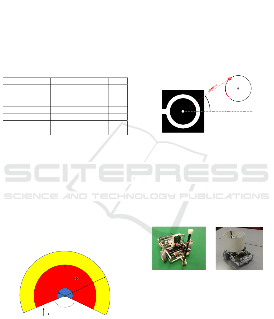
3.2 Ground Truth Range
Figure 3 shows the range of the ground truth, i.e. the
measurement area of the LRF. The LRF is installed in
the origin of the frame that represents tracking envi-
ronment. The laser is fixed in position (0, 0) of the 2D
plane where a polar mapping with a radius of 5.6 m
and an angle comprised of from -120 degrees to +120
degrees.
120º
1.000 mm
4.095 mm
5.600 mm
(0,0)
x
y
Target
(x ,y)
Measurable area
Dead zone
-120º
+120º
0º
Figure 3: Ground truth operation and tracking region.
The blue region represents the area with a preci-
sion of 30 mm of localization. Red region delimits the
area where the sensor’s operating mode provides 12
bits of distance and angle data. This region is widely
used by the academic community, for example (Lima
et al., 2013; Okubo et al., 2009). The area in yellow
includes the maximum region of measuring stipulated
by the manufacturer and the sensor operating mode
provide 18 bits of data (Kawata, 2006).
3.3 Object Description
The object targets used in this paper was a drum lamp-
shade with a diameter of 0.25 m. Within the measur-
able area, LRF locates a circle with the same diameter
of target and returns the position (x
c
,y
c
) of its center
point as showed in Figure 4.
LRF
LRF
θn
Target
(xc,yc)
X
(xn,yn)
Y
(x0,y0)
Figure 4: Fixed laser scanner to detect cylindrical target and
return the center position (x
c
,y
c
).
This target was easily fixed to the mobile robot (it
can also be fixed to other mobile devices) and it is
possible to estimate its position and trajectory. In the
case of the mobile robot with differential drive, the
center of the object must be aligned with the center
point of the traction wheel axis, i.e., the origin of the
axis of rotation, avoiding measurement errors. Figure
5a presents a robot that is incapable of being traceable
by this approach. Figure 5b shows the robot equipped
with the object, which makes it traceable.
(a) (b)
Figure 5: Cylindrical target: (a) Mobile robot without tar-
get. (b) Mobile robot with target used.
3.4 Circular Fitting Calculation
The data from the LRF is in the polar form coordinate
i.e. distance and angle. But the tracking is carried
out in Cartesian coordinate. So the scan data in polar
coordinate needs to be converted into Cartesian coor-
dinate using the sine trigonometry identity, as show in
the following equations:
x
i
= d
i
∗ cos(θ
i
) (2)
Development of a Ground Truth Localization System for Wheeled Mobile Robots in Indoor Environments based on Laser Range-finder for
Low-cost Systems
343

y
i
= d
i
∗ sin(θ
i
) (3)
Given a finite set of points representing the edge of
the target in R
2
,
{
(x
i
,y
i
)|0 ≤ i < n
}
, it is necessary to
find the circle that (in a least-squares sense) fits the
points. First of all, it finds the mean values of x and y,
as presented in next equations.
¯x =
1
n
∑
i
x
i
and ¯y =
1
n
∑
i
y
i
(4)
The problem is solved firstly in the coordinates
(u,v) where u
i
= x
i
− ¯x and v
i
= y
i
− ¯y. Then, trans-
forms it back to (x,y) coordinates.
Let the circumference has the center at (u
c
,v
c
)
and radius R. The algorithm minimizes
S =
∑
i
(g(u
i
,v
i
))
2
(5)
where
g(u,v) = (u − u
c
)
2
+ (v − v
c
)
2
− α (6)
and
α = R
2
(7)
To minimize S, the procedure is to differentiate
S(α,u
c
,v
c
).
∂S
∂α
= 2
∑
i
g(u
i
,v
i
)
∂g
∂α
(u
i
,v
i
) = −2
∑
i
g(u
i
,v
i
) (8)
Thus, if the radius variation is zero, i.e. ∂S/∂α = 0
then:
∑
i
g(u
i
,v
i
) = 0 (9)
Continuing, the differentiation of S with respect to
u
c
results in:
∂S
∂u
c
= 2
∑
i
g(u
i
,v
i
)
∂g
∂u
c
(u
i
,v
i
) (10)
= 2
∑
i
g(u
i
,v
i
)2(u
i
− u
c
)(−1) (11)
= −4
∑
i
(u
i
− u
c
)g(u
i
,v
i
) (12)
= −4
∑
i
u
i
g(u
i
,v
i
) + 4u
c
∑
i
g(u
i
,v
i
)
| {z }
=0 by Eq. 9
(13)
Therefore, considering the radius of the constant tar-
get (Eq. 9) and fixed center point (∂S/∂u
c
= 0) the
following equation is obtained:
∑
i
u
i
g(u
i
,v
i
) = 0 (14)
Similarly, requiring ∂S/∂u
c
= 0 gives
∑
i
u
i
g(u
i
,v
i
) = 0 (15)
Expanding Equation 14 gives:
∑
i
u
i
[u
2
i
+ −2u
i
u
c
+ u
2
c
+ v
2
i
− 2v
i
v
c
+ v
c
− α] = 0
(16)
Defining S
u
=
∑
i
u
i
, S
uu
=
∑
i
u
2
i
and so on, it is
possible to rewrite the equation (16) as:
S
uu
− 2u
c
S
uu
+ u
2
c
S
u
+ S
uvv
− 2v
c
S
uv
+ v
2
c
S
u
− αS
u
= 0
(17)
Since S
u
= 0, this simplifies to
u
c
S
uu
+ v
c
S
uv
=
1
2
(S
uuu
+ S
uvv
) (18)
In a similar way, expanding equation 15 and using
S
v
= 0 gives:
u
c
S
uv
+ v
c
S
uv
=
1
2
(S
vvv
+ S
vuu
) (19)
Solving equation 18 and 19 simultaneously gives
(u
c
,v
c
). Then, going back to (x,y) coordinates, the
real center point of the target (x
c
,y
c
) is obtained by
the follow relation:
(x
c
,y
c
) = (u
c
,v
c
) + ( ¯x, ¯y) (20)
To find the radius R, equation 9 should be ex-
panded:
∑
i
u
2
i
− 2u
i
u
c
+ u
2
c
+ v
2
i
− 2v
i
v
c
+ v
2
c
− α
= 0 (21)
Using S
u
= S
v
= 0 again, it can be obtained R
2
using equation below:
n(u
2
c
+ v
2
c
− α) + S
uu
+ S
vv
= 0 (22)
R
2
= α = u
2
c
+ v
2
c
+
S
uu
+ S
vv
n
(23)
3.5 Laser Scan Application Developed
An application was developed in the Lazarus envi-
ronment to operate the LRF and decode the received
data. It is responsible for tracking the circumference,
as well as being an user interface that allows the def-
inition of parameters such as the region of interest of
the sensor scanning, the value of the radius and its
tolerance as shown in Figure 6.
Communication between the sensor and the ap-
plication is done through a communication protocol
called SCIP2.0, developed by the research group of
the Intelligent Robot Laboratory of the University of
Tsukuba. The communication rate is 9 Mbps through
an USB port (Kawata, 2006). This application is also
capable of performing wireless communication with
another device through a UDP/IP protocol.
ICINCO 2018 - 15th International Conference on Informatics in Control, Automation and Robotics
344
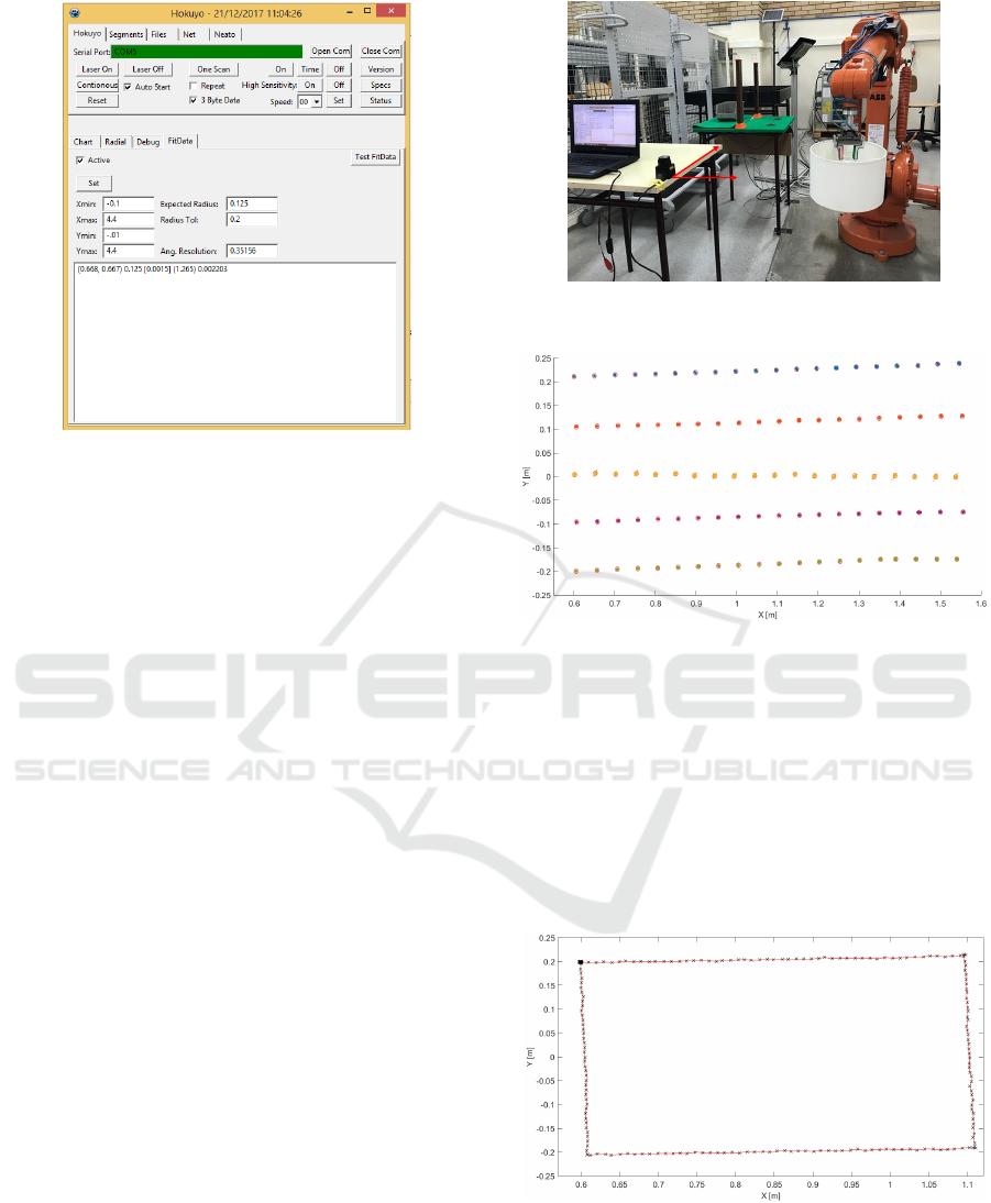
Figure 6: Application interface developed to operate the
LRF.
4 RESULTS
The results of this paper will be divided into two parts.
The first part, a structure with a robotic manipulator
was adopted to evaluate the accuracy of the proposed
system. In the second part, a mobile robot was used
to evaluate five critical points in an area of 16 m
2
.
All data presented in this section refers to the center
point (x
c
,y
c
) of the object that was subjected to the
tracking.
4.1 Target Attached to a Robotic
Manipulator
In order to obtain an accuracy analysis of the ground
truth, the cylindrical object described above was at-
tached to the tool of ABB IRB 1400 robotic manipu-
lator, which has a linear path repeatability of at max-
imum 0.25 mm according to the manufacturer (ABB,
2003). The structure can be seen in Figure 7. The
center of the sensor represents the point (0,0) of the
2D plane scanned by the device, indicated by the red
axes.
The robotic manipulator was positioned at 100
different points/locations (x, y) forming an array of
[5 20] (See Figure 8). It is worth mentioning that the
size of the area respects the reach and limitations of
the manipulator. An algorithm was developed to con-
trol the manipulator by equally spacing the points in
the X direction by 0.05 m and in the Y direction by
0.1 m. At each position of this matrix 200 samples
were obtained. At all locations in the matrix, the error
lies within a circle of 0.01 m in diameter (red Circles
(0,0)
Y
X
Figure 7: Structure adopted to perform ground truth preci-
sion tests.
Figure 8: Measurements obtained at 100 different locations
of the 2D plane using the ABB IRB 1400 robot manipulator.
of Figure 8).
Another test was performed with this same struc-
ture of the robotic manipulator. A linear trajectory
with a constant velocity of 0.25 m/s was made by
performing a rectangular circuit. The points (x; y)
visited by the tool of manipulator were respectively
(0.6;0.2), (1.1; 0.2), (1.1;−0.2), (0.6; −0.2) and fi-
nally (0.6; 0.2). Figure 9 shows the path traveled and
the points sampled by the ground truth.
Figure 9: Linear path performed by robotic manipulator and
cylindrical object tracked by ground truth system.
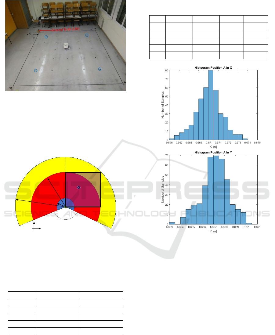
4.2 Target Attached to a Mobile Robot
For this subsection, an area of 4x4 m was organized
to perform the tracking in five different positions (A,
Development of a Ground Truth Localization System for Wheeled Mobile Robots in Indoor Environments based on Laser Range-finder for
Low-cost Systems
345
x
y
(0,0)
E
A
B
C
D
Figure 10: Structure adopted to perform ground truth with
mobile robot.
B, C, D, E) using a mobile robot with the cylindrical
object (see Figure 10).
This area totaling 16 m
2
is contained inside the
range of the LRF as shown the illustration in Figure
11.
-120º
+120º
120º
1 m
4 m
5.6 m
(0,0)
x
y
Robot
(x ,y)
Measurable area
Dead zone
Test area
0º
Figure 11: Testing area respecting the specifications of the
LRF.
Table 2 shows the position of each point that the
mobile robot was positioned. 400 samples were taken
for each position.
Table 2: Positions used for data acquisition.
Position Position X [m] Position Y [m]
A 0.67 0.67
B 0.67 3.33
C 3.33 3.33
D 3.33 0.67
E 2.01 2.01
Table 3 shows the mean and standard deviation of
the 400 samples obtained with the ground truth for
each point by measuring the proposed system’s dis-
persion.
The following Figures show the frequency distri-
bution (histogram) for each of the points in X and Y
Table 3: Mean and standard deviation of the error obtained
with the ground truth.
Pos Mean X Mean Y Std X Std Y
A 0.0001 -0.0028 0.0013 0.0012
B -0.0024 0.0004 0.0024 0.0024
C -0.0117 0.0050 0.0043 0.0042
D 0.0083 -0.0013 0.0017 0.0024
E 0.0189 0.0348 0.0016 0.0017
Figure 12: Histogram of position A in the X and Y direc-
tions.
component. It is possible to notice that most of the
obtained data have a normal distribution.
The developed system presents an absolute aver-
age error of 8 mm in X axis and 9 mm in Y axis.
5 CONCLUSIONS
This paper proposed the use of an LRF to locate and
detect an object in the form of a circle in a 2D plane,
in order to validate (as ground truth) the low cost lo-
cation systems for mobile robots. The used sensor
was the URG-04LX manufactured by Hokuyo and the
target was a cylinder with a diameter of 0.25 m. To
test the system performance two scenarios were used:
one with the target mounted on an industrial manip-
ulator and other with the target mounted on a mobile
robot. In both cases, low noise was observed in the
ICINCO 2018 - 15th International Conference on Informatics in Control, Automation and Robotics
346
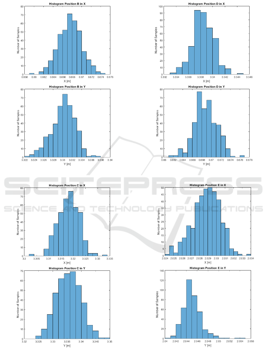
Figure 13: Histogram of position B in the X and Y direc-
tions.
Figure 14: Histogram of position C in the X and Y direc-
tions.
Figure 15: Histogram of position D in the X and Y direc-
tions.
Figure 16: Histogram of position E in the X and Y direc-
tions.
Development of a Ground Truth Localization System for Wheeled Mobile Robots in Indoor Environments based on Laser Range-finder for
Low-cost Systems
347

localization of the target even with a mis-calibration
between the manipulator and the sensor frames. The
results validated the proposed methodology for a low-
cost ground-truth system to be used in mobile robotic
applications.
Finally, as future work is intended to develop
a standardized bench to optimize the alignment of
the sensor and apply the ground truth in a low cost
localization application and the development of a
ROS node enhancing the cooperation among other re-
searchers community.
ACKNOWLEDGEMENTS
This work is financed by the ERDF European
Regional Development Fund through the Opera-
tional Programme for Competitiveness and Interna-
tionalisation - COMPETE 2020 Programme within
project POCI-01-0145-FEDER-006961, and by Na-
tional Funds through the Portuguese funding agency,
FCT -Fundac¸
˜
ao para a Ci
ˆ
encia e a Tecnologia
(Portuguese Foundation for Science and Technol-
ogy), within project SAICTPAC/0034/2015- POCI-
01- 0145-FEDER-016418 and as part of project
UID/EEA/50014/2013.
REFERENCES
ABB, R. (2003). Product manual irb 140. ABB Robotics
Products AB publication, (M2000):7564–1.
Hess, W., Kohler, D., Rapp, H., and Andor, D. (2016). Real-
time loop closure in 2d lidar slam. In Robotics and
Automation (ICRA), 2016 IEEE International Confer-
ence on, pages 1271–1278. IEEE.
Hokuyou (2018). Urg-04lx. Online; accessed 29/01/2018.
Kawata, H. (2006). Urg series communication protocol
specification scip-version2. 0. Drawing No. C-42-
03320B, Oct.
Lima, J. and Costa, P. (2017). Ultra-wideband time of
flight based localization system and odometry fu-
sion for a scanning 3 dof magnetic field autonomous
robot. In Iberian Robotics conference, pages 879–890.
Springer.
Lima, J., Gonc¸alves, J., Costa, P. J., and Moreira, A. P.
(2013). Modeling and simulation of a laser scanner
sensor: an industrial application case study. pages
245–258.
Nepali, M. R., Yadav, N., Dev, U., Mishra, S., and Shrestha,
S. L. (2015). A strategic methodology for 2d map
building in an indoor environment. In Next Genera-
tion Computing Technologies (NGCT), 2015 1st Inter-
national Conference on, pages 797–803. IEEE.
Okubo, Y., Ye, C., and Borenstein, J. (2009). Characteriza-
tion of the hokuyo urg-04lx laser rangefinder for mo-
bile robot obstacle negotiation. In Unmanned Systems
Technology XI, volume 7332, page 733212. Interna-
tional Society for Optics and Photonics.
Olson, E. (2015). M3rsm: Many-to-many multi-resolution
scan matching. In Robotics and Automation (ICRA),
2015 IEEE International Conference on, pages 5815–
5821. IEEE.
Rida, M. E., Liu, F., Jadi, Y., Algawhari, A. A. A., and
Askourih, A. (2015). Indoor location position based
on bluetooth signal strength. In Information Science
and Control Engineering (ICISCE), 2015 2nd Inter-
national Conference on, pages 769–773. IEEE.
Santos, J. M., Portugal, D., and Rocha, R. P. (2013). An
evaluation of 2d slam techniques available in robot
operating system. In Safety, Security, and Rescue
Robotics (SSRR), 2013 IEEE International Sympo-
sium on, pages 1–6. IEEE.
Siciliano, B. and Khatib, O. (2008). Springer handbook of
robotics. Springer Science & Business Media.
Sobreira, H., Moreira, A. P., Costa, P. G., and Lima, J.
(2015). Robust mobile robot localization based on
security laser scanner. In Autonomous Robot Sys-
tems and Competitions (ICARSC), 2015 IEEE Inter-
national Conference on, pages 162–167. IEEE.
Teixid
´
o, M., Pallej
`
a, T., Font, D., Tresanchez, M., Moreno,
J., and Palac
´
ın, J. (2012). Two-dimensional radial
laser scanning for circular marker detection and ex-
ternal mobile robot tracking. Sensors, 12(12):16482–
16497.
Xu, Z., Zhuang, Y., and Chen, H. (2006). Obstacle detec-
tion and road following using laser scanner. In Intel-
ligent Control and Automation, 2006. WCICA 2006.
The Sixth World Congress on, volume 2, pages 8630–
8634. IEEE.
Zeng, S. and Weng, J. (2007). Online-learning and
attention-based approach to obstacle avoidance using
a range finder. Journal of Intelligent and Robotic Sys-
tems, 50(3):219–239.
Zhong, Y., Wu, F., Zhang, J., and Dong, B. (2016). Wifi
indoor localization based on k-means. In Audio, Lan-
guage and Image Processing (ICALIP), 2016 Interna-
tional Conference on, pages 663–667. IEEE.
ICINCO 2018 - 15th International Conference on Informatics in Control, Automation and Robotics
348
