A Framework for Fault-tolerant Control for an Interacting and
Non-interacting Level Control System using AI
Himanshukumar R. Patel and Vipul A. Shah
Instrumentation & Control Dept., Dharmsinh Desai University, College Road, Nadiad, India
Keywords: Actuator Fault, Fault-Tolerant Control, Interacting System, Neural Network, Sensor Fault, System Fault.
Abstract: In chemical and process industries, interacting and non-interacting level control systems are often used for
material storage and processing. The level control parameter is very vital for dealing with faults in a system
(leak), actuator or sensor. System and actuator faults occurring in a system may decrease the performance or
cause instability and unsafe accidents. As observed from practice, when the control performance of the
interacting and non-interacting systems decreases due to occurrence of faults, a fault-tolerant control strategy
(FTC) is required. This paper presents a framework for passive fault tolerant control (PFTC) using a neural
network (NN) and it is designed in order to ensure the stability robustness of the system in the presence of the
faults. In fact, FTC is the potential strategy which is justified by its ability to preserve an acceptable
performance in the presence of faults and process disturbances. To check the effectiveness of the proposed
framework single-tank and two-tank level control experimental setup are used with system and sensor faults.
Simulation and experiment results are presented to demonstrate the capability of the proposed framework of
PFTC using NN to counteract the effect of the system, sensor and actuator faults.
1 INTRODUCTION
Through its various potential applications, an
interacting and non-interacting level control systems
is one of the most used in chemical industries as well
as research purpose in academics. Two-tank
interacting and single-tank non-interacting level
control systems are usually used in chemical
processing and material handling industries to
complete the various processes, so the demands of
reliability, safety, and stability of the system are
particularly important. This is attracting more and
more attention by researchers from past two decades.
Similarly, fault tolerant control strategy applied to a
different multi-tank system with accommodation of
sensor, actuator, and system (leak) fault in (He et al,
2017; Zhou et al, 2012; He et al, 2016; Casavola et al,
2010; Noura et al, 2000).
Over the past four decades, the complexity of a
control system in industry has drastically increased
due to the automation. The purpose of the complex
control system is to improve control performance and
system stability. However, some abnormal events
occur such as faults, sensor/actuator failure, and cause
damage to the system components which are not
encountered at controller design level.
The fault terminology is defined according to
SAFEPROCESS Technical Committee International
Federation of Automatic Control (IFAC) as an
unpermitted deviation of one of the characteristic
property or parameter of the system from the normal
condition (Isermann and Ballé, 1997). Fault-tolerant
Control (FTC) is a specific strategy which has the
ability to maintain acceptable performance and
robustness stability in the presence of faults. In broad
spectrum FTC scheme is classified into two types:
one Active Fault-Tolerant Control (AFTC) and
Passive Fault-Tolerant Control (PFTCS).
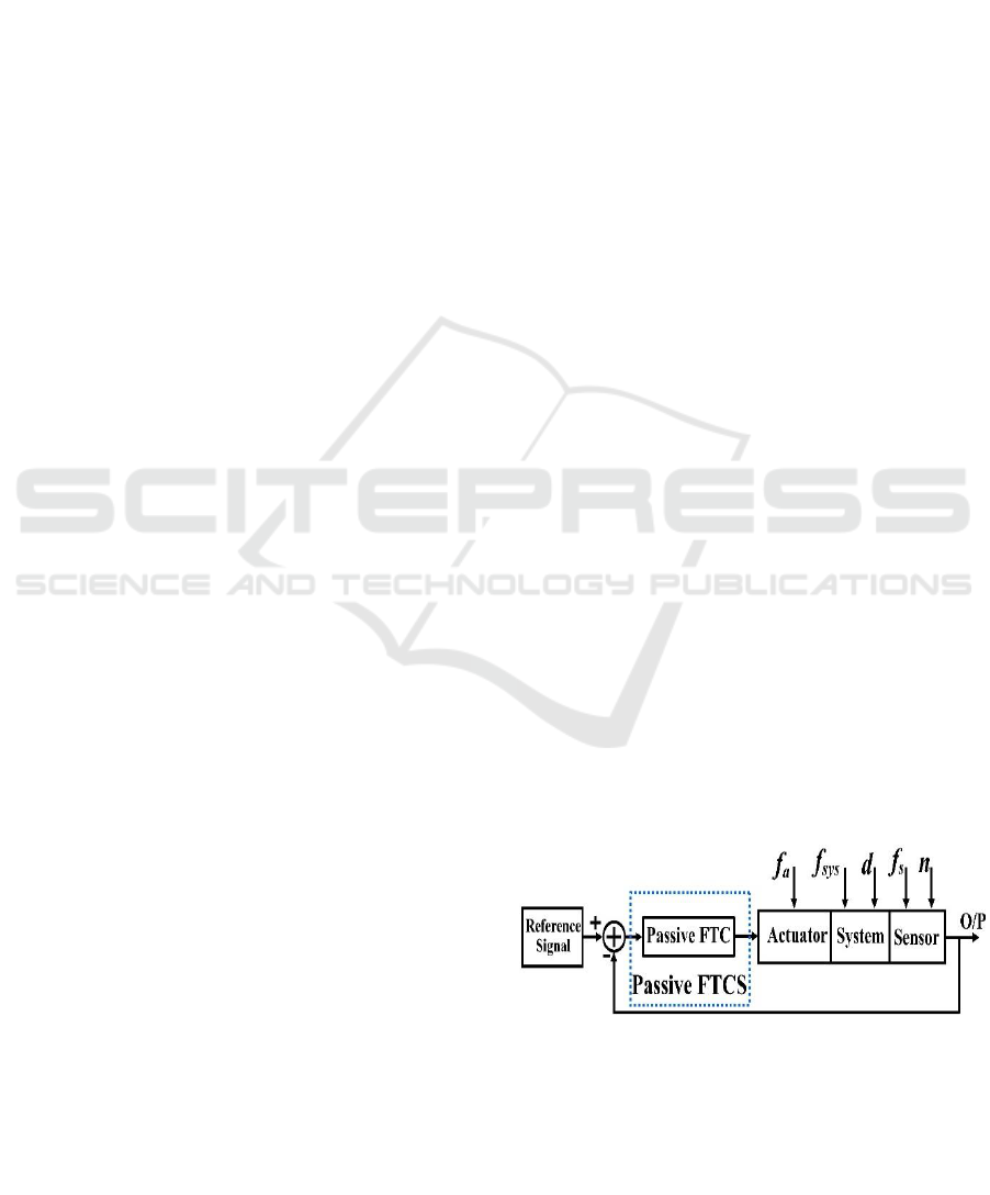
Figure 1: Architecture of a passive FTC (Patel and Shah,
2018a).
The Passive Fault Tolerant Controller is
synthesized to be robust against faults, disturbances
and uncertainties during the design stage. This control
180
Patel, H. and Shah, V.
A Framework for Fault-tolerant Control for an Interacting and Non-interacting Level Control System using AI.
DOI: 10.5220/0006862001800190
In Proceedings of the 15th International Conference on Informatics in Control, Automation and Robotics (ICINCO 2018) - Volume 1, pages 180-190
ISBN: 978-989-758-321-6
Copyright © 2018 by SCITEPRESS – Science and Technology Publications, Lda. All rights reserved

approach is designed based on full prior fault
knowledge about the process faults and uncertainties
using robust control tools to ensure the insensitivity
of the closed loop system to the occurring faults
assumed to be unknown (Patel and Shah, 2018a). The
fault tolerance is achieved in PFTC by maintaining an
acceptable performance and stability properties
without changing the structure of the controller as
shown in fig. 1, without requiring reconfiguration and
without any information relating to the various
failures. The suggested PFTC system subjected to
actuator fault f
a
, process/component fault f
sys
, and
sensor fault f
s
, d is process disturbance and n is sensor
noise.
As compared to the Active Fault Tolerant Control
(AFTC), the PFTC has the advantage of not requiring
the exact fault magnitude value and fault information,
hence it is easy to implement. The PFTC can
guarantee the system stability and performance after
different fault occur and before the FDD or FDI phase
finishes. As the possible faults have been considered
at the PFTC design stage, the structures of PFTC are
oftentimes fixed in the presence of different type of
faults. Several PFTC methods have been proposed
and have been the subject of long research. In the
literature (Sadeghzadeh et al, 2012; Zhaohui and
Noura, 2013; Sharifi et al, 2010; Amoozgar et al,
2012; Merheb et al, 2013) many PFTC strategies have
been proposed, in presence of actuators faults, sensors
faults and system/plant failures or even simultaneous
failures. In (Li et al, 2015) author suggests PFTC
when efficient fault diagnosis procedure is not
available, however prior knowledge of the possible
faults is required. (Patel and Shah, 2018b) has
designed PFTC using fuzzy logic plus conventional
PI controller and implemented on MATLAB
(Simulink) platform with system (leak) fault and
unknown process disturbance.
Figure 2: Architecture of an active FTCS (Gao et al, 2015).
In contrary, the AFTC system has variable
controller structure as shown in fig. 2 based on
supervised approaches called Fault Detection and
Diagnosis (FDD) and Fault Detection and Isolation
(FDI) (Gao et al, 2015). A situation like when there is
no prior knowledge about the fault’s type and effect
on the measured process output, the FDD and FDI
approaches are generally used.
The research of control mathematics for an
improved performance on single-tank (non-
interacting) and two-tank (interacting) level control
system has been performed for several decades. The
research has been encouraged by the desire to
increase levels of safety, reliability, and performance
of these systems, in a wide variety of demanding
industrial applications. In (Orani et al, 2009), a fault
detection strategy has been proposed for a three-tank
system using sliding mode controller, In (Capiluppi.
and Paoli, 2005) distributed fault tolerant scheme is
implemented on two-tank benchmark system with
faults. Authors of (Mendonca et al, 2008) have used
model predictive control (MPC) and soft computing
(fuzzy logic method) to design a fault tolerant control
(FTC) scheme for a three-tank benchmark system
with two faults. In (Basin et al, 2015) author has
designed fault-tolerant algorithm and an experimental
verification of FTC is conducted for a DTS200 three-
tank system through varying fault sources, process
disturbances, input conditions, and disturbances
through inter-tank connections. In (Parikh et al, 2017)
a comparison of the performance of Linear Quadratic
Gaussian Control (LQG) with the Non-linear Model
Predictive Control (NMPC) has been made to achieve
servo plus disturbance rejection and regulatory
control of a three tank system in presence of changing
valve position which serves as the disturbance input.
In this paper, FTC framework is proposed for the
single-tank interacting and two-tank non-interacting
level process control. Neural network and PI control
based passive fault tolerant controller is used in this
framework to ensure the system stability and to track
the desired set point (tank level or height) when an
actuator, sensor, and system (i.e. tank leak) fault
happens, simulations and experimental results are
given using Matlab and single-tank and two-tank
interacting level process experimental setup.
The remainder of this paper is organized as
follows. In Section 2, the framework of PFTC and
process description is explained with a mathematical
model. Selected fault cases are described in
subsection 3 for the non-interacting and interacting
system. Subsequently, the performance of passive
FTC approaches is evaluated in Sections 3 using
simulation and in 4 experimental results with
different faults, cases are evaluated respectively.
Finally, the discussion on results and conclusions are
drawn in Section 5 and 6 respectively.
A Framework for Fault-tolerant Control for an Interacting and Non-interacting Level Control System using AI
181
2 FRAMEWORK AND PROCESS
DESCRIPTION
2.1 Non-interacting Single-tank Level
Process
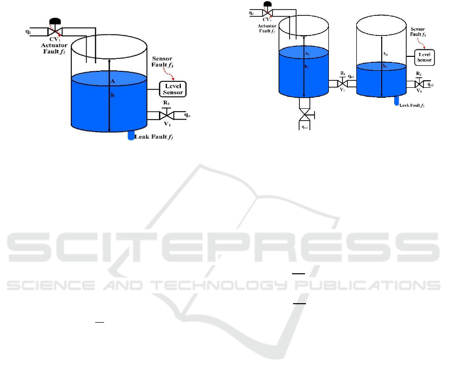
Figure 3: Single-tank non-interacting level process.
Single-tank non-interacting level process is presented
in fig. 3. The process consists of one water tank,
pneumatic control valve and one electric pump. The
controlled variable of system is height of the tank h
and manipulated variable is inlet flow q
i
controlled by
control valve CV
1
. For the simulation the system is
considered with proposed FTC scheme and without
PFTCS for system (leak) and actuator faults. The
process input is (inlet flow rate to tank q
i
using CV
1
)
and the output is (tank height). The process model of
the single-tank level system given by mass balance
and Bernoulli’s law yields:
(1)
Where,
Rate of change of liquid height in tank,
A Cross section area of a tank,
Inlet flow rate of a tank,
Outlet flow rate of a tank.
From the process reaction curve method obtain
the model of single-tank level process is obtained as
given following,
(2)
2.2 Interacting Two-tank Level Process
Two-tank interacting level process demonstrated in
fig. 4. The two-tank interacting level control process
comprises of two tanks and one pneumatic control
valve CV
1
. The system has one input flow rate q
i1
and
one output flow rate q
o2
with interacting or disturbing
flow rate q
o3
to the second tank which is change by
manual valve V
1
.The system has one controlled
variable second tank height h
2
which is controlled by
manipulated variable inlet flow rate of first tank q
i1
using pneumatic control valve CV
1
.
Figure 4: Two-tank interacting level process.
The process model of the two-tank level system is
given by mass balance and Bernoulli’s law yields:
Let h
1
and h
2
be the fluid level in each tank,
measured with respect to the corresponding outlet.
Considering a simple mass balance situation, the rate
of change of fluid volume in each tank equals the net
flow of fluid into the tank. Thus for each of tank 1 and
tank 2, the dynamic equation is developed as follows.
(3)
(4)
Where,
h
1
, and h
2
are height of fluid in tank 1 and tank 2
respectively
A
1
, and A
2
are cross sectional area of tank 1 and tank
2 respectively
q
o3
is flow rate of fluid between tanks
q
i1
is pump flow rate into tank 1 and tank 2
respectively
q
o1
, and q
o2
are flow rate of fluid out of tank 1 and tank
2 respectively.
Bernoulli’s equation for a steady, non-viscous,
incompressible liquid shows that the outlet flows in
each tank is proportional to the square root of the head
of water in the tank.
Similarly, the flow between the two tanks is
proportional to the square root of the head
differential.
ICINCO 2018 - 15th International Conference on Informatics in Control, Automation and Robotics
182
(5)
(6)
(7)
Where α
1
, α
2
, α
3
are proportional constants which
depends on the coefficients of discharge, the cross
sectional area of each tank and the gravitational
constant.
Combining equation (5), (6) and (7) into both
equations (3) and (4), a set of nonlinear state
equations which describe the system dynamics of the
coupled tank are derived as,
(8)
(9)
For the second order configuration that shows on
fig. 4, h
2
is the process variable (PV) and q
i1
is the
manipulated variable (MV). Then, equation (17) and
(18) can be expressed into a form that relates the
manipulated variable, q
i1
and the process variable, h
2
and the final transfer function can be obtained as,
(10)
By the process reaction curve method the
linearized mathematical model of the two-tank
interacting single input single output (SISO) level
control system is as following,
(11)
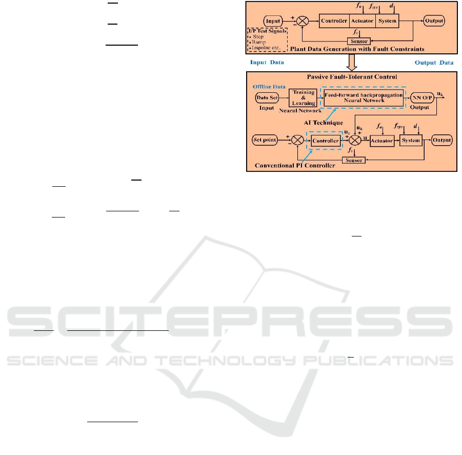
2.3 Proposed Framework of PFTC
System
For the constraints like- system, sensor, and actuator
faults in interacting and non-interacting level control
process a new framework is proposed for FTC. For
these passive FTC scheme is designed using soft
computing method (neural network) NN and PI
controller. It is used to detect the faults in system and
gives superior closed loop control performance and
stability even in presence of faults.
PFTCS gives remarkable results in the occurrence
of system, sensor and actuator faults in system. The
framework of PFTC is presented in fig. 5. The NN is
used to incorporate the detecting the fault and
overcome the consequences of the same on the
system performance and stability.
Figure 5: Proposed framework of FTCS.
PI controller transfer function is given as follows:
(12)
Where,
G
c
is PI controller transfer function,
K
P
is proportional controller gain,
K
i
is integral controller gain,
is integral time.
(13)
The PI controller parameters proportional gain K
P
and Integral gain K
i
are identified using manual
tuning method. The gain values of the PI controller as
following;
K
P
= 0.8 and K
i
= 0.004.
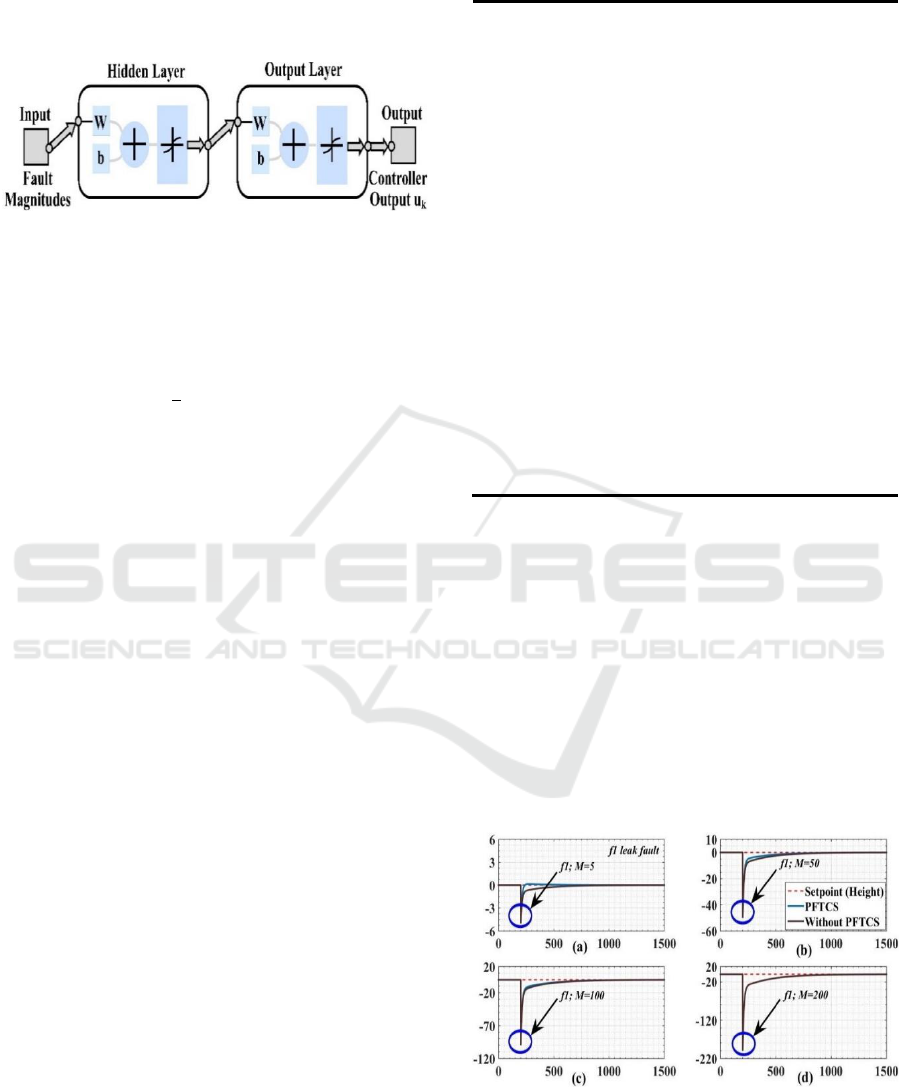
For detection of the fault in the system Feed-
Forwarded Backpropagation Neural Network
(FFBNN) is designed and the structure of the same
presented in fig. 6. For training the FFBNN one input
and one output variable chosen, at input side different
fault magnitudes are taken within normalized range
of [-1.7178, 1.6605] and at the output side getting
controller output u
k
has same normalized range [-
1.7178, 1.6605].
The FFBNN is trained from different magnitude
of the sensor and system faults and found the
appropriate control output according to fault
magnitudes. The FFBNN trained for curtain range of
fault magnitudes beyond that the output of the
controller is degraded gradually. The FFBNN having
A Framework for Fault-tolerant Control for an Interacting and Non-interacting Level Control System using AI
183
one hidden and one output layer. The hidden layer
having 10 trained weights from input, the output
having 1 layer and 10 trained weights.to the output
layer.
Figure 6: Internal structure of feed-forward back
propagation neural network.
Performance of PFTCS and without PFTCS
summarized in terms of Mean Square Error (MSE)
and is defined as follows:
(14)
Where,
is the vector denoting values of n number of
predictions,
is a vector representing n number of true values,
n are number of samples.
2.4 Justifications for the Selection of
Fault Scenarios
In this paper, system (leak) fault represent situations
where the tank-level reduces drastically and control
valve is not able to cope with the faulty situation and
hence control performance degrades. The control
signal generated from controller is not sufficient to
control the tank height. Actuator faults is considered
as a second faults in single-tank, which represents
situation where the final control element (control
valve) does not opening completely and it gives lesser
flow rate as compared to actual. These circumstances
lead to performance deterioration.
For evaluating proposed framework of FTC for non-
interacting level control process, actuator and system
(leak) faults and different cases in terms of magnitude
value have been chosen as shown in table 1. For
designing FTC framework, conventional PI control
strategy plus neural network (NN) is adopted for
passive FTCSs.
Table 1: Fault scenarios taken for non-interacting level
control process in simulation.
Sr.
No.
Faults
Types
Failure details
1.
System
(leak) f
1
Tank leak at bottom
(M=Magnitude value)
1. Leak fault with M= 5
2. Leak fault with M= 50
3. Leak fault with M= 100
4. Leak fault with M= 200
2.
Actuator
f
2
Control valve opening with
error
1. Actuator fault with M=0.5
2. Actuator fault with M= 1
3. Actuator fault with M= 2
4. Actuator fault with M= 5
3.
Sensor
f
3
Control valve opening with
error
NA
4.
Beyond
design
basis
fault d
Process disturbances
NA
3 SIMULATION RESULTS
3.1 Non-Interacting System
Fig. 7 and Fig. 8 represents the comparative results
between proposed framework of FTC and without
FTC on single-tank level control process with a leak
and actuator fault constraint in the system. To validate
the proposed framework different magnitudes of
faults are simulated on the system and, error results
are shown in table 2 and 3.
Figure 7: Comparative result of non-interacting process
with system fault.
ICINCO 2018 - 15th International Conference on Informatics in Control, Automation and Robotics
184

Figure 8: Comparative result of non-interacting process
with actuator fault.
Table 2: PFTC framework performance comparison for
system fault in non-interacting system.
Sr.
No.
Controller Scheme
f
1
MSE
1.
PFTCS
M=5
0.0921
Without PFTCS
0.1751
2.
PFTCS
M=50
13.3824
Without PFTCS
17.5104
3.
PFTCS
M=100
61.0852
Without PFTCS
70.0417
4.
PFTCS
M=200
261.5534
Without PFTCS
280.1668
*f
1
denotes system fault
Table 3: PFTC framework performance comparison for
actuator fault in non-interacting system.
Sr.
No.
Controller Scheme
f
2
MSE
1.
PFTCS
M=0.5
0.0156
Without PFTCS
0.0264
2.
PFTCS
M=1
0.0625
Without PFTCS
0.0976
3.
PFTCS
M=2
0.2499
Without PFTCS
0.3750
4.
PFTCS
M=5
1.5617
Without PFTCS
2.1672
*f
2
denotes actuator fault
From observing the control performance
increasing the leak fault magnitude in non-interacting
level control system the performance is reducing
drastically.
3.2 Interacting System
For evaluating proposed framework of FTC for
interacting level control process, actuator and system
(leak) faults and different cases in terms of magnitude
value have been chosen as shown in table 4. For
designing the FTC framework, conventional PI
control strategy plus neural network (NN) is adopted
for passive FTCSs. For interacting two-tank level
process system (leak) fault considering in tank 1 and
actuator fault considering in control valve CV
1
which
control the manipulated variable inlet flow rate q
i1
.
Table 4: Fault scenarios taken for interacting level control
process in simulation.
Sr.
No.
Faults
Types
Failure details
1.
System
(leak) f
1
Tank leak at bottom
(M=magnitude)
1. Leak fault with M= 5
2. Leak fault with M= 10
3. Leak fault with M= 50
4. Leak fault with M= 100
2.
Actuator
f
2
Control valve opening with error
1. Actuator fault with M=0.2
2. Actuator fault with M=0.5
3. Actuator fault with M= 1
4. Actuator fault with M= 2
3.
Sensor
f
3
Control valve opening with error
NA
4.
Beyond
design
basis
fault d
Process disturbances
NA
Fig. 9 and Fig. 10 represents the comparative results
between proposed framework of FTC and without
FTC on two-tank level control process with a leak and
actuator fault constraint in the system. Table 5 and 6
clearly show that suggested framework gives better
control performance in presence of system and
actuator faults.
A Framework for Fault-tolerant Control for an Interacting and Non-interacting Level Control System using AI
185
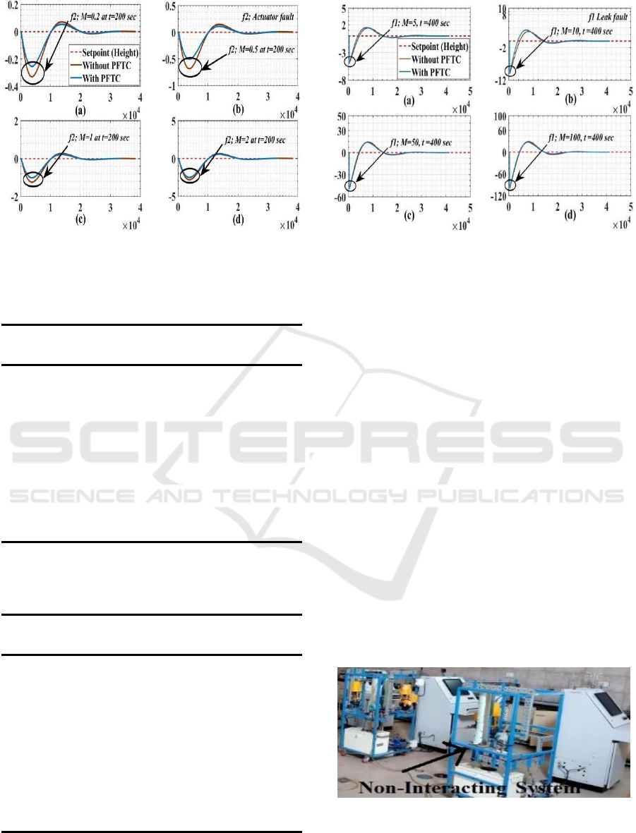
Figure 9: Comparative result of interacting process with
system (leak) fault.
Table 5: PFTC framework performance comparison for
leak fault in interacting system.
Sr.
No.
Controller Scheme
f
1
MSE
1.
PFTCS
M=5
0.9031
Without PFTCS
1.3488
2.
PFTCS
M=10
3.6344
Without PFTCS
5.3952
3.
PFTCS
M=50
91.6850
Without PFTCS
134.8805
4.
PFTCS
M=100
369.2292
Without PFTCS
539.5221
*f
1
denotes system fault
Table 6: PFTC framework performance comparison for
actuator fault in interacting system.
Sr.
No.
Controller Scheme
f
2
MSE
1.
PFTCS
M=0.5
0.0094
Without PFTCS
0.0138
2.
PFTCS
M=1
0.0376
Without PFTCS
0.0596
3.
PFTCS
M=2
0.1506
Without PFTCS
0.1964
4.
PFTCS
M=5
0.9411
Without PFTCS
1.0261
*f
2
denotes actuator fault
Figure 10: Comparative result of interacting process with
actuator fault.
4 EXPERIMENTAL RESULTS
4.1 Experimental Setup
Experimental setup of single-tank non-interacting
level control system presented in fig. 11. PFTC
strategy using AI is developed and run in the
MTALAB platform. The physical system input and
output are communicated to MATLAB with OPC
tool. To actuate the final control element (Control
valve) according to PFTC strategy control output and
to get level value of the single-tank from level sensor
and feedback in MATLAB software (PFTC strategy)
for computing the control output, Programmable
Logic Controller (PLC) is interfaced between single-
tank non-interacting level control system and
MTLAB software. In the non-interacting level control
system the manipulated variable is in flow rate of tank
1 q(
i
) and controlled variable is tank height. One
system (leak) and one sensor faults are considered to
validate the proposed PFTC strategy.
Figure 11: Experimental setup for non-interacting single
tank system.
ICINCO 2018 - 15th International Conference on Informatics in Control, Automation and Robotics
186
To verify the effectiveness of the proposed PFTC
scheme on interacting and non-interacting level
control system with faulty conditions, PFTC
framework is applied on real-time experimental set up
of same system. To check the efficacy of framework
system (leak), sensor, and actuator fault apply in
different nature at different time period with change
in magnitude value. A sensor fault and process
disturbances are not considering at the time of
experiments.
Table 7: Fault scenarios taken for non-interacting level
control process in simulation.
Sr.
No.
Faults
Types
Failure details
1.
System
(leak) f
1
Single-Tank leak at bottom
1. Two Leak one fault with M=
4.76 to 5 from (t=275 to 350
sec) after second fault with
M=11
2. Leak fault with M= 13.3 to
M=16.4 from (t=250 to 350
sec) after M=16.4
2.
Actuator
f
2
Control valve opening with
error
1. Actuator fault with
M=10% high value
3.
Sensor
f
3
Control valve opening with
error
NA
4.
Beyond
design
basis
fault d
Process disturbances
NA
Figure. 12: Experimental setup for interacting two tank
system.
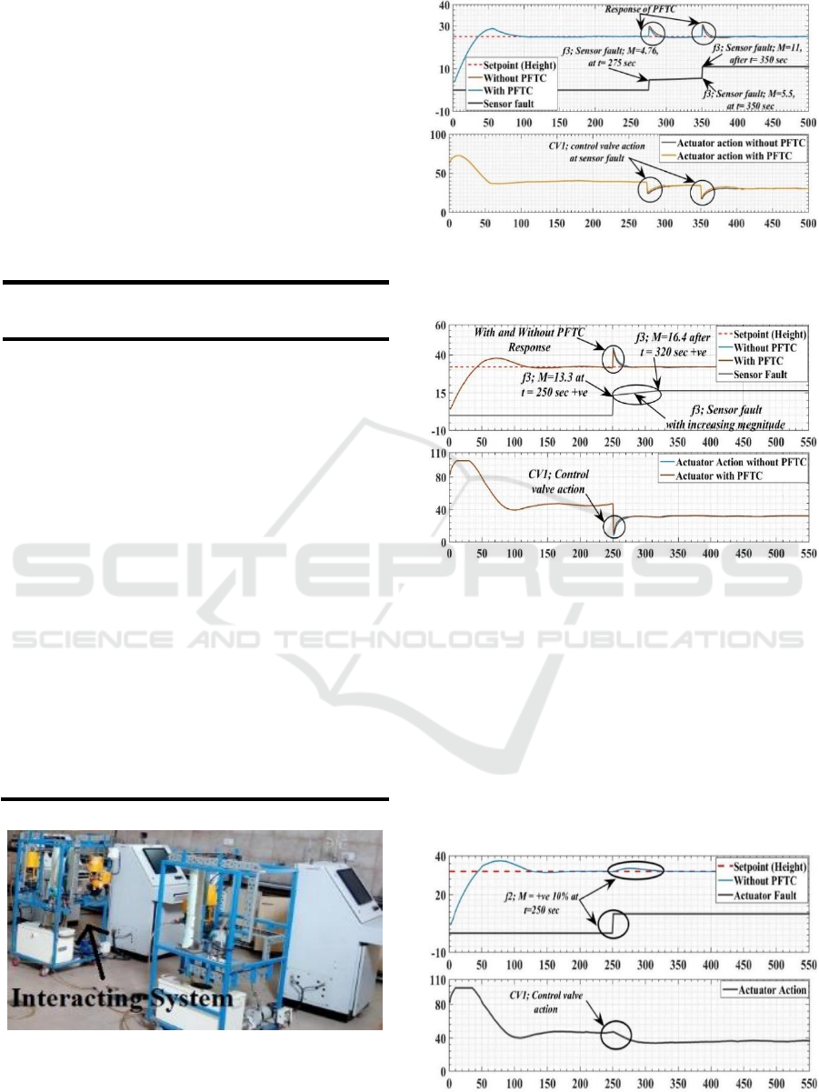
Figure. 13: Comparative experimental Comparative
experimental result of non-interacting level process with
multi sensor (+Ve increasing) fault.
Figure 14: Comparative experimental result of non-
interacting level process with multi sensor (+Ve increasing)
fault.
Proposed PFTC strategy using AI is applied on
experimental setup with sensor and actuator faults
with deferent magnitudes in the single-tank non-
interacting level control system and form observing
fig. 13 to fig. 15 it clearly shows that proposed AI
strategy of PFTC gives superior response as
compared to without PFTC strategy. The control
performance of the proposed PFTC strategy is
presented in table 8 in terms of MSE error.
Figure 15: Comparative experimental result of non-
interacting level process with actuator (+Ve) fault.
A Framework for Fault-tolerant Control for an Interacting and Non-interacting Level Control System using AI
187
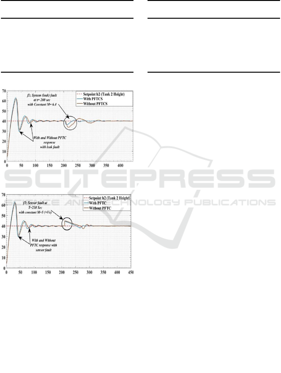
Table 8: PFTC framework performance comparison for
sensor fault in non-interacting system.
Sr.
No.
Controller
Scheme
f
3
MSE
1.
PFTCS
Increasing
fault up to
M=11
6.9591
Without
PFTCS
10.7435
2.
PFTCS
Increasing
fault up to
M=16.4
18.0146
Without
PFTCS
20.9394
*f
3
denotes sensor fault
Figure 16: Comparative experimental result of interacting
level process with system (leak) (+Ve) fault.
Figure 17: Comparative experimental result of interacting
level process with system (leak) (+Ve) fault.
Experimental results of the two-tank interacting
level control system shown in the fig. 16 and fig. 17.
The sensor and leak faults are introduced in to real-
time system with different magnitudes at the different
times as presented in table 9. The error value shows
the effectiveness of the proposed PFTC with different
type of faults and magnitude. For the two-tank real-
time system constant fault magnitude considered.
Table 9: PFTC framework performance comparison for
system fault in non-interacting system.
Sr.
No.
Controller
Scheme
Fault
MSE
1.
PFTCS
f
1
M=6.4
22.4251
Without
PFTCS
30.5977
2.
PFTCS
f
3
M=5 (+Ve)
21.4513
Without
PFTCS
27.6791
*f
1
denotes system fault
*f
3
denotes sensor fault
5 RESULTS AND DISCUSSION
Performance of proposed framework of PFTC is
applied and verified on two different processes one
for non-interacting single-tank level process and a
second system for interacting two-tank level process.
To check the efficacy of the PFTCS with constraint
of three types of faults simulation (MATLAB)
platform is used. Also PFTCS is applied on real-time
system and find the response with different fault types
and magnitude are found. Pproposed PFTCS
framework will give better control response compare
to without PFTCS which are shown in terms of MSE
error. The proposed framework of PFTCS scheme is
capable to accommodate sensor, actuator, and system
(leak) faults as shows in result figure. The main
advantage of the proposed scheme is to incorporate
soft computing technique (i.e. neural network) to
design the controller, hence no need to find out an
accurate measurement of the faults. The proposed
framework has required some tuning to cope up the
malfunctioning occurs at one time (i.e. all faults
occurs at same time). In experimental results only
leak and sensor fault are introduce on two-tank level
control system. Effect of the actuator fault in same
system is not explored in experiments.
6 CONCLUSION
This article attributes of the proposed framework of
PFTC using conventional PI feedback controller and
artificial intelligence (Neural Network) for a system
(leak), actuator, and sensor faults. The proposed
PFTC strategies, capable of maintaining a stability as
well as control performance when a different
abnormality occurs like fault and disturbances. From
ICINCO 2018 - 15th International Conference on Informatics in Control, Automation and Robotics
188

the observing and analyzing the simulation and real-
time results, when a fault occurs the PFTC scheme
using neural network plus PI controller design had
achieved its desired set point and stability.
Meanwhile, the PFTC using PI feedback control
design achieves its desired set point but does not
improve its steady state error as compared to PFTC
scheme. Hence, it can be proved that proposed PFTC
scheme using neural network plus PI controller mode
design is one of the most efficient techniques to
ensure the system performance does not degrade and
set point is achieved in spite of fault and disturbances.
Framework of PFTCS is a realistic choice when
efficient fault diagnosis procedure is not available.
However how to take into account the prior
knowledge of the system faults, is a key work in the
passive fault tolerant control system design. In further
works PFTC scheme can be designed for multiple
faults like system and sensor faults occurring at the
same time. Also other than neural network another
soft computing techniques can be used (e.g. Adaptive
Neuro-Fuzzy Inference System (ANFIS)) for PFTC
scheme.
ACKNOWLEDGMENT
This work was carried out in Instrumentation and
Process Control (IPC) Laboratory at the Department
of Chemical Engineering, Dharmsinh Desai
University, Nadiad-387001, Gujarat, India. The
authors also would like to express very great
appreciation to Dr. M. S. Rao and Mr. Pratik Soni for
his valuable and constructive suggestions during the
planning and development of this research work.
REFERENCES
Amoozgar, M.H., Chamseddine, A. & Zhang, Y., 2012.
“Fault-tolerant fuzzy gain scheduled PID for a
quadrotor helicopter test bed in the presence of actuator
faults,” In Advances in PID Control Brescia (Italy),
March 28-30. IFAC Proceedings Volumes, pp. 282–
287.
Basin, M. et al., 2015. “A finite-time-convergent fault-
tolerant control and its experimental verification for
DTS200 three-tank system,” In International Workshop
on Recent Advances in Sliding Modes (RASM 2015) 9-
11 April Istanbul (Turkey). IEEE, pp. 1–6.
Capiluppi, M. & Paoli, A., 2005. “Distributed fault tolerant
control of the two-tank system benchmark,” In 44
th
IEEE Conference on Decision and Control 15-15
December Seville (Spain). IEEE, pp. 1361–1366.
Casavola, A. et al., 2010. “A fault-tolerant real-time
supervisory scheme for an interconnected four-tank
System,” In American Control Conference (ACC 2010)
Baltimore June-30-July-2. IEEE, pp. 6210–6215.
Gao, Z., Cecati, C. & Ding, S.X., 2015. A Survey of Fault
Diagnosis and Fault-Tolerant Techniques—Part I: Fault
Diagnosis With Model-Based and Signal-Based
Approaches. IEEE Transactions on Industrial
Electronics, 62(6), pp.3757–3767.
He, X. et al., 2016. Active fault-tolerant control for an
internet-based networked three-tank system. IEEE
Transactions on Control Systems Technology, 24(6),
pp.2150–2157.
He, X. et al., 2017. Fault-Tolerant Control for an Internet-
Based Three-Tank System: Accommodation to Sensor
Bias Faults. IEEE Transactions on Industrial
Electronics, 64(3), pp.2266–2275.
Isermann, R. & Ballé, P., 1997. Trends in the application of
model based fault detection and diagnosis of technical
processes. Control Engineering Practice, 5(5), pp.709–
719.
Li, Z. et al., 2015. “Design of Passive Fault Tolerant
Control of A Process System,” In the 27th Chinese
Control and Decision Conference (2015 CCDC) 23-25
May Qingdao (China). IEEE, pp. 2776–2781.
Mendonca, L.F., Sousa, J.M.C. & Sa da Costa, J.M.G.,
2008. “Fault accommodation of an experimental three
tank system using fuzzy predictive control,” In IEEE
International Conference on Fuzzy Systems (IEEE
World Congress on Computational Intelligence) 1-6
June Hong Kong (China). IEEE, pp. 1619–1625.
Merheb, A.-R., Noura, H. & Bateman, F., 2013. “Passive
fault tolerant control of quadrotor UAV using regular
and cascaded Sliding Mode Control,” In Conference on
Control and Fault-Tolerant Systems (SysTol) 9-11
October. IEEE, pp. 330–335.
Noura, H., Theilliol, D. & Sauter, D., 2000. Actuator fault-
tolerant control design: demonstration on a three-tank-
system. Journal of International Journal of Systems
Science, 31(9), pp.1143–1155.
Orani, N., Pisano, A. & Usai, E., 2009. “Fault Detection and
Reconstruction for a Three-Tank System via high-order
sliding-mode observer,” In IEEE Control Applications,
(CCA) & Intelligent Control, (ISIC) 8-10 July St.
Petersburg (Russia). IEEE, pp. 1714–1719.
Parikh, N. et al., 2017. “A comparison between NMPC and
LQG for the level control of three tank interacting
system,” In Indian Control Conference (ICC 2017) 4-6
January Guwahati (India). IEEE, pp. 200–205.
Patel, H.R. & Shah, V.A., 2018a. Fault Tolerant Control
Systems: A Passive Approaches for Single Tank Level
Control System. Journal of Instrumentation and Control
Engineering, 6(1), pp.11–18.
Patel, H.R. & Shah, V.A., 2018b. “Fuzzy Logic Based
Passive Fault Tolerant Control Strategy for a Single-
Tank System with System Fault and Process
Disturbances,” In Proc. 5
th
International Conference on
Electrical and Electronics Engineering (ICEEE),
Istanbul (Turkey), 3-5 May 2018, pp. 257–262.
A Framework for Fault-tolerant Control for an Interacting and Non-interacting Level Control System using AI
189

Sadeghzadeh, I. et al., 2012. “Active Fault Tolerant Control
of a quadrotor UAV based on gainscheduled PID
control,” In 25
th
IEEE Canadian Conference on
Electrical and Computer Engineering (CCECE)
Montreal 29 April-2 May. IEEE, pp. 1–4.
Sharifi, F. et al., 2010. “Fault tolerant control of a quadrotor
UAV using sliding mode control,” In Conference on
Control and Fault-Tolerant Systems (SysTol) Nice 6-8
October. IEEE, pp. 239–244.
Zhaohui, C. & Noura, H., 2013. “A composite Fault
Tolerant Control based on fault estimation for
quadrotor UAVs,” In 8
th
Conference on Industrial
Electronics and Applications (ICIEA) Melbourne 19-21
June. IEEE, pp. 236–241.
Zhou, D.H. et al., 2012. Leakage fault diagnosis for an
internet-based three-tank system: An experimental
study. IEEE Transactions on Control Systems
Technology, 20(4), pp.857–870.
ICINCO 2018 - 15th International Conference on Informatics in Control, Automation and Robotics
190
