
Physical Layer Impairments in Cascaded Multi-degree CDC
ROADMs with NRZ and Nyquist Pulse Shaped Signals
Diogo G. Sequeira
1
, Luís G. Cancela
1,2
and João L. Rebola
1,2
1
Optical Communications and Photonics Group, Instituto de Telecomunicações, Lisbon, Portugal
2
Department of Information Science and Technology, Instituto Universitário de Lisboa (ISCTE-IUL), Lisbon, Portugal
Keywords: ASE Noise, Broadcast and Select, In-Band Crosstalk, Nyquist Pulse, Optical Filtering, ROADMs, Route
and Select.
Abstract: Nowadays, reconfigurable optical add/drop multiplexers (ROADMs) are mainly based on broadcast and
select (B&S) and route and select (R&S) architectures. Moreover, the most used components to implement
the colorless, directionless and contentionless (CDC) ROADM add/drop structures are the multicast
switches (MCSs) and the wavelength selective switches (WSSs). In-band crosstalk, amplified spontaneous
emission (ASE) noise accumulation and optical filtering are physical layer impairments (PLIs) that become
more enhanced in a CDC ROADM cascade. In this work, we investigate the impact of these PLIs in a
cascade of CDC ROADMs based on both B&S and R&S architectures, with MCSs and WSSs-based
add/drop structures and for nonreturn-to-zero (NRZ) rectangular and Nyquist pulse shaped signals. We
show that the optical filtering impairment is more limiting for a R&S architecture. We also show that the
ASE noise accumulation after 32 cascaded ROADMs leads to a 10 dB optical signal-to-noise ratio (OSNR)
penalty for all ROADM degrees investigated. We have also concluded that the in-band crosstalk leads to a 1
dB OSNR penalty, after 13 and 24 cascaded 16-degree CDC ROADMs based on B&S for, respectively,
NRZ rectangular and Nyquist pulse shapes. For a R&S architecture, the in-band crosstalk is not so harmful.
1 INTRODUCTION
The continuous and exponential increase of data
traffic in recent years has been putting the optical
network infrastructures in a constant pursuit of new
technologies that can transport huge amounts of bits
in a more cost effective and efficient way.
Technologies, such as coherent detection, advanced
digital signal processing, polarization division
multiplexing (PDM) and wavelength division
multiplexing (WDM) are now fundamental to
achieve these goals (Roberts et al., 2017).
Moreover, as the data traffic becomes more
heterogeneous in terms of bit rate and modulation
format, and the connections duration decreases, a
more dynamic, flexible and reconfigurable optical
transport network is required (Jinno, 2017). These
requirements can be provided by the optical network
nodes, currently known as reconfigurable optical
add/drop multiplexers (ROADMs) with colorless,
directionless and contentionless (CDC) add/drop
structures (Gringeri et al., 2010). The CDC ROADM
nodes can express, add and drop any WDM signal
without restrictions and contention of wavelengths
(Feuer et al., 2011).
The most used architectures to implement the
ROADM nodes are the broadcast and select (B&S)
and route and select (R&S) architectures (Simmons,
2014). The B&S is the cheapest implementation, but
has higher insertion losses and poorer isolation than
the R&S architecture. On the other hand, the R&S
architecture is the best choice in terms of isolation of
adjacent channels and has low insertion losses, but
since it is based on wavelength selective switches
(WSSs), the filtering effects are more relevant and
the cost is higher than the B&S architecture.
In a multi-degree CDC ROADM-based optical
network, the physical layer impairments (PLIs), such
as optical filtering, amplified spontaneous emission
(ASE) noise accumulation and in-band crosstalk,
limit the number of ROADM nodes that an optical
signal can pass along the network (Tibuleac and
Filer, 2010). These PLIs are cumulative along the
network and depend not only on the ROADM
architecture, e.g. B&S or R&S, but also on the
ROADM add/drop structures.
In the literature, some studies were performed to
Sequeira, D., Cancela, L. and Rebola, J.
Physical Layer Impairments in Cascaded Multi-degree CDC ROADMs with NRZ and Nyquist Pulse Shaped Signals.
DOI: 10.5220/0006861102230231
In Proceedings of the 15th International Joint Conference on e-Business and Telecommunications (ICETE 2018) - Volume 1: DCNET, ICE-B, OPTICS, SIGMAP and WINSYS, pages 223-231
ISBN: 978-989-758-319-3
Copyright © 2018 by SCITEPRESS – Science and Technology Publications, Lda. All rights reserved
223

address the impact of these PLIs on the network
performance. In (Filer and Tibuleac, 2012), the
optical filtering and in-band crosstalk impairments
due to a cascade of WSSs, have been considered, but
neglected the ROADM architectures types. In (Filer
and Tibuleac, 2014), the impact of the ROADM
architectures are considered, but the influence of the
ROADM add/drop structures has been neglected. In
(Pan and Tibuleac, 2016), the filtering and in-band
crosstalk impact were evaluated considering the
37.5 GHz flexible grid. In that study, the authors
considered a colorless add/drop structure. In (Morea
et al., 2015), the impact of filtering for both the
50 GHz fixed grid and 37.5 GHz flexible grid is
evaluated. In that study, the crosstalk impact is not
considered, as well as the contentionless ROADM
feature. In all these previous studies, the ASE noise
accumulation is not considered. Instead, the authors
considered that the ASE noise is totally loaded at the
system input (Pan and Tibuleac, 2016) or at the
system output (Morea et al., 2015).
In this work, we investigate the impact of the
optical filtering, ASE noise accumulation and
in-band crosstalk generated inside CDC ROADMs
on the network performance, through Monte-Carlo
(MC) simulation. PDM quadrature phase-shift
keying (PDM-QPSK) signals at 100-Gb/s, with
25 Gbaud symbol rate, for the 50 GHz fixed grid are
considered, although other scenarios could be
simulated (Fabrega et al., 2016). We investigate both
nonreturn-to-zero (NRZ) rectangular (Wang and
Lyubomirsky, 2010) and Nyquist pulse shaped
signals. These last signals considered a roll-off
factor (β) equal to 0.1, which is a typical value
(Morea et al., 2015). This study is performed by
properly modelling the ROADM nodes, considering
both B&S and R&S architectures and different
add/drop structures, based on multicast switches
(MCSs) (Way, 2012) and WSSs (Yang et al., 2017).
This work is organized as follows. Section 2
describes the simulation model of the multi-degree
CDC ROADM-based optical network. Details on the
ROADM add/drop structures are provided in
Subsection 2.1. In Subsection 2.2, the filtering
transfer functions used to model the ROADM
components are presented and characterized. The
optical filtering impact is studied in Section 3, for
both ROADM architectures, add/drop structures and
pulse shapes signals. Section 4 investigates the in-
band crosstalk level evolution in a CDC ROADM
cascade also for both ROADM architectures,
add/drop structures and signal shapes. In Section 5,
the impact of in-band crosstalk on the network
performance is evaluated. Finally, in Section 6, the
conclusions of this work are provided.
2 CDC ROADM-BASED OPTICAL
NETWORK MODEL
In this section, we present the simulation model of
an optical network based on multi-degree CDC
ROADMs, as well as, the in-band crosstalk terms
generated inside these ROADMs and the ASE noise
added to the primary signal along the network.
Subsection 2.1 describes the ROADM add/drop
structures modelling. Subsection 2.2 presents the
filtering transfer functions used to model the
ROADM components.
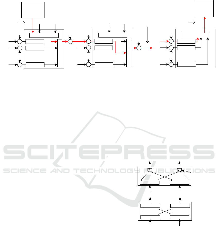
Figure 1 depicts the simulation model of an
optical network based on multi-degree CDC
ROADMs. The red line in this figure represents the
light-path of the primary signal (i.e., the signal that
is taken as a reference to study the impact of the
PLIs),
, since it is added to the network, in the
first ROADM node, until it is dropped, in the
M
th
ROADM,
,
. Throughout this work, we
consider a 100-Gb/s NRZ rectangular or Nyquist
pulse shaped signal and QPSK modulation for the
primary signal. In our MC simulator, we do not
consider the fiber transmission effects, so the fiber
impairments are neglected.
Regarding the in-band crosstalk signals
originated along the multi-degree CDC
ROADM-based optical network, we consider that all
interfering signals have the same modulation format
and bit rate as the primary signal, but with different
arbitrary transmitted symbols, characterized by a
phase difference and a time misalignment between
the primary signal and in-band interferers (Cancela
et al., 2016). These interfering signals arise from the
ROADM inputs and, also, from the ROADM add
structures, denominated, respectively,
,
and
,
, with M indicating the ROADM node and R
the ROADM degree in which they are originated.
We consider that all ROADM degrees are sources of
interfering signals. In the ROADM inputs and
ROADM add structures, the interfering signals pass
through the respective components (e.g. WSS) and
then are added to the primary signal.
Concerning the ASE noise addition, we consider
that the ASE noise is added both at the ROADM
inputs and outputs. The optical amplifier (OA) at the
ROADM inputs is used to compensate the optical
path losses, whereas the OA at the ROADM outputs
is used to compensate the losses inside the ROADM
node (Zami, 2013).
OPTICS 2018 - International Conference on Optical Communication Systems
224
.
.
.
...
S
in
X
1,add2
X
1,add R
S
o,1
...
S
o,2
1
st
R-degree ROADM 2
nd
R-degree ROADM
M
th
R-degree ROADM
X
1,in1
X
1,in2
X
1,inR
+
+
+
ASE
noise
Add Structure
WSS
ASE
noise
.
.
.
...
X
2,add2
X
2,add R
X
2,in2
X
2,inR
+
+
+
ASE
noise
Add Structure
WSS
ASE
noise
.
.
.
X
M,inR
S
o,M-1
X
M,in2
+
ASE
noise
+
ASE
noise
S
o,M
.
.
.
+
+
+
ASE
noise
Drop Structure
ASE
noise
.
.
.
Add
signal
Express
signal
.
.
.
Comp. A
.
.
.
.
.
.
...
...
Drop
signal
...
...
Comp. A
Comp. A
Comp. A
Comp. A
Comp. A
Comp. A
Comp. A
Comp. A
Optical
Coherent
Receiver
Optical
Transmitter
Figure 1: Simulation model of an optical network based on M cascaded R-degree CDC ROADMs.
The node losses are considered independent of
the ROADM architectures. So, in the MC simulator,
we consider that all OAs have the same
characteristics: noise figure, gain and optical
bandwidth. Hence, they impose the same optical
signal-to-noise ratio (OSNR) at its outputs.
Throughout this work, the OSNRs presented
correspond to the OSNR at the output of each OA
and it is measured in the 0.1 nm reference bandwidth
(Essiambre et al., 2010). The ASE noise is
considered as an additive white Gaussian noise.
To drop the primary signal, in the last ROADM,
we use an ideal coherent detection receiver model
(Essiambre et al., 2010). In the decision circuit,
inside the optical coherent receiver, the bit error rate
(BER) is obtained by direct-error counting, for a
target BER of 10
−3
. The number of counted errors
considered is 1000 and either the primary signal and
the interfering signals are generated with 256
symbols. Our studies are done only for a single
polarization, a 50-Gb/s QPSK signal, which
corresponds to a 25 Gbaud symbol rate. We consider
that polarization transmission effects are ideal and
that ROADM components are polarization
independent. We also assume that the optical
receiver performs an ideal detection for both
polarizations (Seimetz and Weinert, 2006). Hence,
the results presented in this work, for a single
polarization, are valid for both polarizations.
As can be observed in Figure 1, at the ROADM
inputs, the signals pass through Component A,
which depends on the architecture used. In ROADM
nodes based on a B&S architecture, Component A is
an optical splitter, while with a R&S architecture,
this optical splitter is replaced by a WSS. In both
architectures, at the ROADM outputs, the signals go
through a WSS (Simmons, 2014). In Figure 1, to
simplify, we only show the output of one direction
of the ROADMs, to where the primary signal is sent.
2.1 ROADM Add/Drop Structures
In our ROADM model, we consider both MCSs and
WSSs-based add/drop structures. Figure 2 depicts
the model used to implement the drop structure
(Colbourne and Collings, 2011). Figure 2 (a)
considers a N×M MCS-based drop structure and
Figure 2 (b) considers a N×M WSS-based drop
structures.
N×1
Optical
Switches
N×M
MCS
Splitter 1×MSplitter 1×M
...
...
... ...
N×M
WSS
WSS 1×M WSS 1×M
...
WSS N×1
WSS N×1
... ...
......
...
(a)
(
b
)
...
...
1
M
1
N
N
1
M
1
...
...
Figure 2: CDC ROADM N×M drop structures based on (a)
MCSs and (b) WSSs.
The corresponding model for the add structures
is obtained in a similar way, by just having in mind
the direction of the data flow. As can be observed
from Figure 2, the MCSs are based on 1×M splitters
and N×1 optical switches. As such, they are not
wavelength selective as the WSS structures. In terms
of in-band crosstalk generation, since inside a N×M
WSS, the interfering signals pass through the
isolation of two WSSs, the interferers are of second
order, instead of the first order interferers that appear
Physical Layer Impairments in Cascaded Multi-degree CDC ROADMs with NRZ and Nyquist Pulse Shaped Signals
225

on the N×M MCSs. On the other hand, the WSS
structures have higher costs and are more filtering
selective than the MCSs. In terms of modelling these
add/drop structures, the MCSs are modelled by one
filtering stage, while the WSSs are modelled by two
filtering stages.
2.2 ROADMs Filtering Model
We consider two types of transfer functions to
model the filtering inside the ROADM components,
a transfer function for modelling the WSS pass
through effect, represented by
, and another
transfer function for modelling the WSS blocking
effect represented by
. The transfer function
is modelled by a super Gaussian optical filter
with lowpass equivalent transfer function given by
(Pulikkaseril, 2011)
⁄
.
(1)
where n is the super Gaussian filter order, which, in
this work, is set to n = 4, and B
0
is the 3 dB
bandwidth, which is set to 41 GHz, usually used for
the 50 GHz fixed grid (Filer and Tibuleac, 2012). On
the other hand, the lowpass equivalent transfer
function
is given by
1
1
.
⁄
.
(2)
where a is the blocking amplitude in linear units,
10
. The 3 dB bandwidth of this stopband
filter, when setting B to 41 GHz, is equal to,
approximately, 48 GHz. Figure 3 shows the transfer
functions,
(Figure 3 (a)) and
, with
A = 40 dB (Figure 3 (b)).
(a) (b)
Figure 3: Transfer function of the (a) 4
th
order super
Gaussian optical passband filter,
, and (b) optical
stopband filter,
, with A = 40 dB.
3 OPTICAL FILTERING IMPACT
The impact of the optical filtering in the ROADM
cascade represented in Figure 1 is assessed in this
section. The primary signal, along its light-path,
passes through several filtering stages inside the
ROADMs before reaching its destination. These
cascaded filters lead to the narrowing of the
available optical bandwidth, and, consequently, to an
OSNR penalty due to the optical filtering (Hsueh,
2012). To evaluate the OSNR penalty only due to
optical filtering, i.e., the difference between the
required OSNR with and without the filtering
impairment, we only add ASE noise at the end of the
ROADM cascade, to the drop signal
,
represented in Figure 1. To study the impact of the
optical filtering, we neglect the in-band crosstalk
interferers influence on the primary signal.
In this work, we consider a maximum of 32
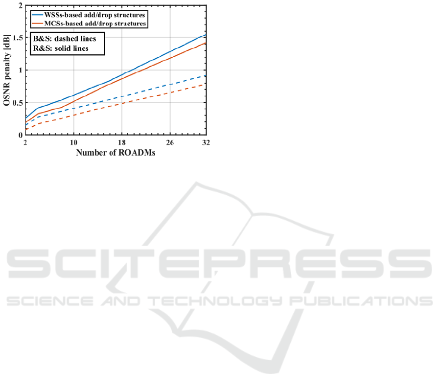
ROADMs in cascade (Basch et al., 2006). Figure 4
depicts the OSNR penalty due to optical filtering as
a function of the number of ROADMs based on a
B&S (dashed lines) and a R&S (solid lines)
architectures, for both add/drop structures: WSSs
(blue lines) and MCSs (red lines) and considering
NRZ rectangular signals. From Figure 4, we can
conclude that, the add/drop structures do not have a
significant impact in terms of OSNR penalty due to
optical filtering. The difference between the OSNR
penalty obtained with MCSs and WSSs-based
add/drop structures is less than 0.15 dB. This
difference corresponds to the additional filtering that
the signal experiences when it is added and dropped
with WSSs-based add/drop structures.
Regarding the difference observed, in Figure 4,
between the curves for B&S and R&S architectures,
the OSNR penalty due to optical filtering, as
expected, is lower for a B&S architecture (Filer and
Tibuleac, 2014), since with this architecture, the
signal is not filtered at the ROADM inputs. For this
architecture, an OSNR penalty of 1 dB is not
reached after 32 cascaded ROADMs. For ROADM
nodes based on a R&S architecture, penalties of
~1.5 dB are observed after 32 cascaded ROADMs.
Considering a 1 dB OSNR penalty as the limit for
this penalty, the signal can cross 20 and 22 ROADM
nodes, respectively, with WSSs and MCSs-based
add/drop structures.
The same studies have been done for Nyquist
pulse shaped signals with β = 0.1. In this scenario,
the optical filtering impact is very low, causing
OSNR penalties lower than 0.1 dB after 32 cascaded
ROADMs. This is explained by noting that the
bandwidth of the Nyquist signals is, approximately,
equal to symbol rate, 25 GHz, and the 3 dB
bandwidth of the optical filters for the 50 GHz fixed
grid is much larger than the symbol rate, 41 GHz,
OPTICS 2018 - International Conference on Optical Communication Systems
226
originating a negligible OSNR penalty due to optical
filtering impact, as was also reported in (Morea et
al., 2015).
Figure 4: OSNR penalty due to optical filtering as a
function of the number of ROADMs, for a BER of 10
−3
,
B&S (dashed lines) and R&S (solid lines) architectures,
WSSs (blue lines) and MCSs (red lines) add/drop
structures and NRZ rectangular signals.
4 IN-BAND CROSSTALK LEVEL
IN A CDC ROADM CASCADE
In this section, the in-band crosstalk level evolution
along a cascade composed by 32 CDC ROADMs is
evaluated for A = 40 dB, several ROADM degrees,
considering both ROADM architectures, different
add/drop structures and rectangular and Nyquist
pulse shaped signals. The crosstalk level, at each
ROADM output, is defined by
,
,
,
⁄
,
where
,
is the average power of all interfering
signals and
,
is the primary filtered signal
average power, at the output of the M
th
ROADM
(Cancela et al., 2016). The crosstalk level shown in
Figures 5 and 6 is obtained by averaging the power
of all crosstalk sample functions generated in the
MC simulator.
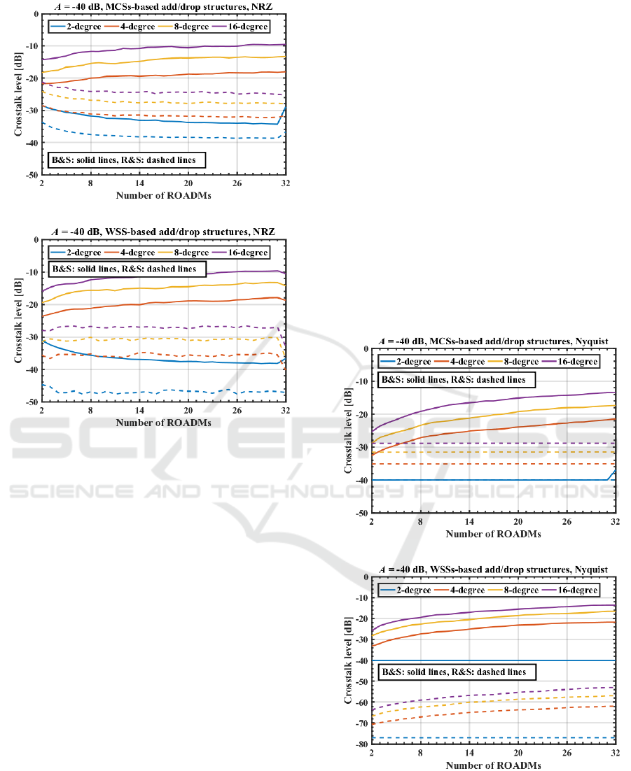
Figure 5 depicts the evolution of the crosstalk
level, in a cascade of 32 CDC ROADMs, as a
function of the number of ROADMs based on a
B&S (solid lines) and a R&S (dashed lines)
architecture, considering NRZ rectangular signals.
Figure 5 (a) considers MCSs and Figure 5 (b)
considers WSSs-based add/drop structures. Several
observations can be made from this figure.
First, as expected, the crosstalk level increases
with the increase of the ROADM degree.
Second, for a R&S architecture, the crosstalk
level along the ROADM cascade is lower than for a
B&S architecture, since, the interfering signals
experience more blocking filtering stages in a R&S
than in a B&S architecture.
Third observation: we can see in Figure 5 (a),
with MCSs-based add/drop structures, a decrease of
the crosstalk level along the network for the R&S
architecture (dashed lines). This can be explained by
noting that the interfering signals that came from the
first ROADM add structure are considered first
order crosstalk terms (i.e. they pass through one
stopband filter), whereas all the other interfering
signals that appear along the light-path are second
order terms (i.e. they pass through two stopband
filters). In this way, the first order in-band terms will
define the crosstalk level, which has a decrease
along the ROADM cascade due to the filtering
performed by the WSSs.
On the other hand, for a B&S architecture (solid
lines), the interfering signals are all first order terms,
so the total crosstalk level increases along the
ROADM cascade, except for 2-degree ROADMs. In
this case, the crosstalk level decreases along the
cascade until the last ROADM, where the crosstalk
level increases. This behaviour occurs because in the
add section of the first ROADM and in the ROADM
input of the last ROADM, first order terms are
originated. All the other ROADMs, where the signal
is expressed, do not contribute with first order terms,
consequently, the ROADM filtering decreases the
crosstalk level until the last ROADM. Note that, at
the end of the ROADM cascade, for 16-degree
ROADMs with MCSs-based add/drop structures, an
increase of 4 dB in the crosstalk level is observed.
Figure 5 (b) depicts the crosstalk level evolution
but with WSSs-based add/drop structures. Here, we
can observe a crosstalk level decreases in the last
ROADM. This decrease is more abrupt for the R&S
architecture, because the interfering signals pass
through three stopband filters in the last ROADM
node (one in the “route” WSS and two in the “drop”
WSS). This crosstalk level decrease is not observed
for 2-degree ROADMs based on a B&S architecture
(blue solid line), for the same reason mentioned in
the previous paragraph. For the R&S architecture,
with WSS-based add/drop structures, the crosstalk
level is practically constant along the ROADM
cascade, since all interfering terms generated are
second order. Consequently, the crosstalk level is,
mostly, defined in the first ROADM node.
Physical Layer Impairments in Cascaded Multi-degree CDC ROADMs with NRZ and Nyquist Pulse Shaped Signals
227
(a)
(b)
Figure 5: Crosstalk level as a function of the number of
ROADMs, A = 40 dB, for both architectures, B&S (solid
lines) and R&S (dashed lines), NRZ rectangular signals,
several ROADM degrees and (a) MCSs and
(b) WSSs-based add/drop structures.
Figure 6 shows the crosstalk level evolution
along the ROADM cascade, but considering Nyquist
pulse shaped signals. Figure 6 (a) refers to MCSs
and Figure 6 (b) to WSS-based add/drop structures.
In Figure 6 (a), for a R&S architecture (dashed
lines), a constant crosstalk level along the ROADM
cascade can be observed. This behaviour is justified
by the fact that the interfering terms from the first
ROADM add structure are first order terms, while
the other interfering terms coming from the other
ROADMs in the cascade, either from the ROADM
inputs or from ROADM add structure, are all second
order terms. Besides that, since the optical stopband
filter in the first ROADM is more effective with
Nyquist signals than with NRZ rectangular signals,
the crosstalk level remains constant along the
ROADM cascade.
For a B&S architecture (solid lines), the behavior
of the crosstalk level evolution along the optical
network is similar with the previously obtained for
NRZ rectangular signals. Nevertheless, the crosstalk
level variation between the first and the last
ROADM of the cascade, in this case, is higher than
with NRZ rectangular signals. For example, for
16-degree ROADM based on a B&S architecture
with MCSs-based add/drop structures, we have a
variation of ~4 dB and ~11 dB, respectively, for
NRZ rectangular and Nyquist pulse shaped signals.
The main reason is because the stopband filters used
in this work, for the 50 GHz fixed grid, provide a
better blocking of in-band crosstalk interfering
signals for the Nyquist pulse shaped signals, since
the Nyquist signals bandwidth with β = 0.1 is,
approximately, one half in comparison with the NRZ
rectangular signals bandwidth. For the same reason,
for Nyquist pulse shaped signals, we can observe
that after two cascaded ROADMs based on a B&S
architecture and with MCSs-based add/drop
structures, Figure 6 (a), the crosstalk level is lower
~10 dB than for NRZ rectangular pulse shaped
signals, Figure 5 (a).
(a)
(b)
Figure 6: Crosstalk level as a function of the number of
ROADMs, A = 40 dB, for both architectures, B&S (solid
lines) and R&S (dashed lines), Nyquist pulse shaped
signals, several ROADM degrees and (a) MCSs and
(b) WSSs-based add/drop structures.
OPTICS 2018 - International Conference on Optical Communication Systems
228

From Figure 6 (b), we can conclude that, with
Nyquist pulse shaped signals, WSSs-based add/drop
structures and a R&S architecture (dashed lines), the
crosstalk levels originated are very low, below
−50 dB. For a B&S architecture (solid lines), the
crosstalk levels obtained are very similar with those
obtained with MCSs-based add/drop structures in
Figure 6 (a).
5 IN-BAND CROSSTALK
IMPACT
After having studied the crosstalk level generated in
a CDC ROADM cascade, for both B&S and R&S
architectures, MCSs and WSSs-based add/drop
structures, NRZ rectangular and Nyquist pulse
shaped signals and several ROADM degrees, the
OSNR penalty due to in-band crosstalk is evaluated
in this section.
In the previous section, we have concluded that
with A = 40 dB and a R&S architecture, the
crosstalk levels generated along the ROADM
cascade are below −20 dB. Consequently, this
crosstalk level does not lead to a significant network
degradation. Thus, in this section, we only study the
OSNR penalty due to the in-band crosstalk for the
B&S architecture.
Figure 7 shows the required OSNR, at the output
of each OA, for a target BER of 10
−3
, as a function
of the number of ROADMs for NRZ rectangular
(solid lines) and Nyquist (dashed lines) pulse shaped
signals and a B&S architecture. The same studies
have been done for the R&S architecture and the
required OSNRs obtained are very similar, with
differences below 0.5 dB. Note that, in this work, we
consider that the required OSNR is the OSNR
imposed in each OA to reach a target BER of 10
−3
at
the end of the ROADM cascade. This required
OSNR is measured without the in-band crosstalk
impairment, but including the impact of the optical
filtering and ASE noise addition in all ROADM
inputs and outputs, as shown in Figure 1. In this
work, we consider that all ROADM nodes introduce
the same insertion losses regardless the ROADM
architecture and ROADM add/drop structures. For
future work, we will consider the insertion losses
depending on the ROADM architectures, and, also,
on the ROADM add/drop structures.
From Figure 7, we can conclude that, the
required OSNR variation with the number of
ROADMs and the ROADMs degree is very similar
for both signal shapes studied. For Nyquist pulse
shaped signals, there is an improvement of the
required OSNR that reaches 1 dB for 16-degree
ROADMs. For all ROADM degrees considered,
there is a degradation of about 10 dB of the required
OSNR from a cascade of 2 nodes to a cascade of 32
ROADMs nodes. For example, for 2-degree
ROADMs, the required OSNR after 2 nodes is
19 dB and after 32 nodes, it is approximately 29 dB,
for NRZ rectangular signals.
To calculate the OSNR penalty due to in-band
crosstalk shown in the Figure 8 and 9, we considered
the reference OSNR from the results plotted in
Figure 7.
Figure 8 shows the OSNR penalty due to in-band
crosstalk as a function of the number of ROADMs,
for a target BER of 10
−3
, A = −40 dB, considering
both add/drop structures, MCSs (dashed lines) and
WSSs (solid lines), for several ROADM degrees and
NRZ rectangular signals. From this figure, we can
conclude that, for an OSNR penalty of 1 dB, the
maximum number of cascaded ROADMs decreases
with the ROADM degree increase.
Figure 7: Required OSNR for a BER equal to 10
−3
as a
function of the number of ROADMs, for the NRZ
rectangular (solid lines) and Nyquist (solid lines) pulse
shaped signals, several ROADM degrees and a B&S
architecture.
For example, for 8-degree ROADMs, the optical
signal can pass through 20 and 28 nodes,
respectively, with MCSs and WSSs-based add/drop
structures. While for 16-degree ROADMs, where
more interfering signals arise in each node, the
signal can pass through 8 and 13 ROADMs,
respectively, with MCSs and WSSs-based add/drop
structures. So, by implementing the add/drop
structures with WSSs instead of MCSs, an
improvement of 8 and 5 ROADMs has been
obtained, respectively, with degree 8 and 16.
Figure 9 shows the OSNR penalty due to in-band
crosstalk as a function of the number of 16-degree
ROADMs, for NRZ rectangular (red lines) and
Physical Layer Impairments in Cascaded Multi-degree CDC ROADMs with NRZ and Nyquist Pulse Shaped Signals
229
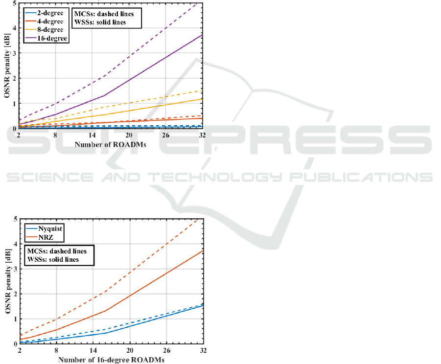
Nyquist (blue lines) pulse shaped signals. From this
figure, we can observe a significant improvement on
the ROADMs number that an optical signal can pass
with the Nyquist pulse shape. An OSNR penalty of
1 dB is reached after 13 and 24 cascaded 16-degree
ROADMs, for, respectively, NRZ rectangular and
Nyquist pulse shaped signals and with WSSs-based
add/drop structures. It means an improvement of 11
ROADMs. For MCSs-based add/drop structures, the
improvement is about 15 ROADMs. This
improvement is related with the crosstalk level at the
end of the ROADM cascade, which is higher for
NRZ rectangular signals than for Nyquist pulse
shaped signals, as shown in Figures 5 and 6.
Figure 8: OSNR penalty due to the in-band crosstalk as a
function of the number of ROADMs, for a BER of 10
−3
,
A = −40 dB, add/drop structures based on MCSs (dashed
lines) and on WSSs (solid lines) and NRZ rectangular
signals.
Figure 9: OSNR penalty due to in-band crosstalk as a
function of the number of 16-degree ROADMs, for a BER
of 10
−3
, A = −40 dB, add/drop structures based on MCSs
(dashed lines) and on WSSs (solid lines) and for NRZ
rectangular (red lines) and Nyquist (blue lines) pulse
shaped signals.
Comparing the impact of the ASE noise
accumulation with the in-band crosstalk impact in a
CDC ROADM cascade, we can conclude that, the
ASE noise accumulation has a greater impact than
the in-band crosstalk in terms of OSNR penalty. As
referred, at the end of a cascade with 32 ROADMs,
the ASE noise accumulation leads to an OSNR
penalty of, approximately, 10 dB. The in-band
crosstalk, in the worst case (i.e., with NRZ
rectangular signals, MCSs-based add/drop
structures, a B&S architecture and 16-degree
ROADMs) leads to an OSNR penalty slightly higher
than 5 dB.
6 CONCLUSIONS
In this work, we have investigated the impact of
PLIs, namely, optical filtering, in-band crosstalk and
ASE noise accumulation in a CDC ROADM cascade
for both B&S and R&S architectures and with MCSs
and WSSs-based add/drop structures. Our studies
have been performed considering 100-Gb/s QPSK
signals for the 50 GHz fixed grid with NRZ
rectangular and Nyquist pulse shapes.
Our results showed that the impact of the optical
filtering with NRZ rectangular signals and a R&S
architecture is more significant than with a B&S
architecture. For CDC ROADMs based on a R&S
architecture, the optical signal can pass through 20
and 22 ROADM nodes, respectively, with WSSs and
MCSs-based add/drop structures, until an OSNR
penalty of 1 dB is reached. The B&S architecture
does not lead to an OSNR penalty of 1 dB at the end
of 32 cascaded ROADMs. For Nyquist shaped
signals, we have observed that the impact of optical
filtering is negligible, for both ROADM
architectures.
In terms of the in-band crosstalk level generated
in a ROADM cascade, we have concluded that, for a
R&S architecture, the crosstalk level is below
–20 dB due to the enhanced signal blocking imposed
by the higher number of WSSs in the light-path. In
ROADMs based on a B&S architecture, the OSNR
penalty due to in-band crosstalk is higher with
MCSs-based add/drop structures. An OSNR penalty
of 1 dB is reached after a NRZ rectangular QPSK
signal passes through 20 and 8 CDC ROADM
nodes, respectively, with degree 8 and 16. An
improvement is reached using WSSs-based add/drop
structures. The OSNR penalty of 1 dB due to
in-band crosstalk is reached at the end of 28 and 13
cascaded ROADMs, respectively, with degree 8 and
16. For Nyquist pulse shaped signals, the OSNR
OPTICS 2018 - International Conference on Optical Communication Systems
230

penalty is lower than for NRZ rectangular signals,
for both add/drop structures. Our results showed an
improvement of 15 and 11 ROADMs in cascade
with Nyquist pulse shapes for 16-degree ROADMs,
and, respectively, MCS and WSSs-based add/drop
structures.
We, also, have seen that, the ASE noise
accumulation along the ROADM cascade leads to a
10 dB OSNR degradation after 32 cascaded
ROADMs and should be considered as a limitation
factor to the number of ROADMs that a signal can
cross in an optical network.
ACKNOWLEDGEMENTS
This work was supported by Fundação para a
Ciência e Tecnologia (FCT) of Portugal within the
project UID/EEA/50008/2013.
REFERENCES
Basch, E., et al. (2006). Architectural tradeoffs for
reconfigurable dense wavelength-division
multiplexing systems. IEEE J. Sel. Top. Quantum
Electron., 12(4), 615-626.
Cancela, L., et al. (2016). Analytical tools for evaluating
the impact of in-band crosstalk in DP-QPSK signals.
NOC, 6-11.
Colbourne, P. and Collings, B. (2011), ROADM
Switching Technologies. OFC, pp. OTuD1.
Essiambre, R., (2010). Capacity limits of optical fiber
networks. J. Lightw. Technol., 28(4), 662-701.
Fabrega, J., et al. (2016). On the filter narrowing issues in
elastic optical networks. J. Opt. Commun. Netw., 8(7),
A23-A33.
Feuer, M., et al. (2011). Intra-node contention in dynamic
photonic networks. J. Lightw. Technol., 29(4), 529-
535.
Filer, M. and Tibuleac, S. (2012). Generalized weighted
crosstalk for DWDM systems with cascaded
wavelength-selective switches. Opt. Exp., 20(16),
17620-17631.
Filer, M. and Tibuleac, S. (2014). N-degree ROADM
architecture comparison: Broadcast-and-select versus
route-and-select in 120 Gb/s DP-QPSK transmission
systems. OFC, pp. Th1I-2.
Gringeri, S., et al. (2010). Flexible architectures for optical
transport nodes and networks. IEEE Commun. Mag.,
48(7), 40-50.
Hsueh, Y., et al. (2012). Passband narrowing and crosstalk
impairments in ROADM-enabled 100G DWDM
networks. J. Lightw. Technol., 30(24), 3980-3986.
Jinno, M. (2017). Elastic optical networking: Roles and
benefits in beyond 100-Gb/s era. J. Lightw. Technol.,
35(5), 1116-1124.
Morea, A., et al. (2015). Throughput comparison between
50-GHz and 37.5-GHz grid transparent networks. J.
Opt. Commun. Netw., 7(2), A293-A300.
Pan, J. and Tibuleac, S. (2016). Filtering and crosstalk
penalties for PDM-8QAM/16QAM super-channels in
DWDM networks using broadcast-and-select and
route-and-select ROADMs. OFC, pp. W2A-49.
Pulikkaseril, C. (2011). Spectral modeling of channel band
shapes in wavelength selective switches. Opt. Exp.,
19(9), 8458-8470.
Roberts, K., et al. (2017). Beyond 100 Gb/s: capacity,
flexibility, and network optimization. J. Opt. Commun.
Netw., 9(4), C12-C24.
Seimetz, M. and Weinert, C. (2006). Options, feasibility,
and availability of 2×4 90º hybrids for coherent optical
systems. J. Lightw. Technol., 24(3), 1317-1322.
Simmons, J. (2014). Optical network design and planning.
Springer, 2
nd
edition.
Tibuleac, S. and Filer, M. (2010). Transmission
impairments in DWDM networks with reconfigurable
optical add-drop multiplexers. J. Lightw. Technol.,
28(4), 557-598.
Wang, Y. and Lyubomirsky, I. (2010). Impact of DP-
QPSK pulse shape in nonlinear 100 G transmission. J.
Lightw. Technol, 28(18), 2750-2756.
Way, W. (2012). Optimum architecture for M×N multicast
switch-based colorless, directionless, contentionless,
and flexible-grid ROADM. OFC, pp. NW3F-5.
Woodward, S., et al., (2010). Intra-node contention in a
dynamic, colorless, non-directional ROADM. OFC.
Yang, H., et al. (2017). Low-cost CDC ROADM
architecture based on stacked wavelength selective
switches. J. Opt. Commun. Netw., 9(5), 375-384.
Zami, T. (2013). Current and Future Flexible Wavelength
Routing Cross‐Connects. Bell Labs Technical Journal,
18(3), 23-38.
Physical Layer Impairments in Cascaded Multi-degree CDC ROADMs with NRZ and Nyquist Pulse Shaped Signals
231
