
A Steganogaphic Scheme for MAC-Independent Opportunistic Routing
and Encoding (MORE) Protocol
Mohamed Amine Belhamra and El Mamoun Souidi
Laboratory of Mathematics, Computer Science, Applications and Information Security,
Mohammed V University in Rabat, Faculty of Sciences, BP 1014 RP Rabat, Morocco
Keywords:
Network Steganography, Random Linear Network Coding, Transfer Matrix, MAC-independent Opportunistic
Routing & Encoding (MORE).
Abstract:
In this paper we describe a distortion-less network steganographic scheme for wireless multicast communica-
tions using MORE (MAC-independent Opportunistic Routing & Encoding) Protocol. An efficient implemen-
tation protocol that can run directly on top of 802.11 for wireless Random Linear Network Coding (RLNC)
settings. To do so, we take advantage on a first hand, of the transfer matrix of the protocol (i.e. the random
process managing the coefficients of the linear combinations), and on a second hand, of the ability of a sender
node to change its transmission range at ease, and broadcast packets to all neighbouring nodes. Specifically,
we use MORE’s transfer matrix as our covert channel, where we hide secret messages in each transmission
phase.
1 INTRODUCTION
Steganography is the art and science of hiding a se-
cret message within an ordinary message (the cover-
medium) in such a way that no one realizes there is
a hidden message, apart from the sender and the in-
tended receiver. There exist a large number of stega-
nographic techniques for hiding messages in different
types of media. We constrain our considerations to
techniques based on various functions of communi-
cation protocols of contemporary communication net-
works. This specific class of techniques is referred to
as Network Steganography (NS).
NS schemes are mainly based on protocol functi-
ons associated with the Open System Interconnect-
Reference Model (OSI-RM) layers, where the covert
channels are established using the control data, timing
properties of transmission or of the user data. Many
NS schemes have been studied in the literature. In
fact, a survey classification based on patterns realized
by (Wendzel et al., 2015), has been a good idea to
tackle the subject.
In (Szczypiorski, 2003; Szczypiorski and Mazur-
czyk, 2016) for example, the authors proposed sche-
mes exploiting the physical and data link layers. (Sz-
czypiorski and Mazurczyk, 2016) introduced a phy-
sical layer method called WiPad (Wireless Padding)
intended for IEEE 802.11 OFDM (orthogonal fre-
quency division multiplexing) networks, where the
secret data is inserted into the padding of transmit-
ted symbols. Another method proposed by (Grabski
and Szczypiorski, 2013) embeds data within the cy-
clic prefix, and its embedding capacity varies accor-
ding to the used modulation (see Table 4) : In Binary
Phase Shifting Keying (BPSK), in Quadrature Phase
Shifting Keying (QPSK), in 16-Quadrature Ampli-
tude Modulation (QAM) and in 64-QAM.
(Szczypiorski, 2003) proposed a data link layer
method called Hidden Communication System for
Corrupted Networks (HICCUPS), based on using
transmission frames with intentionally wrong check-
sums. In WLANs, all terminals can detect data con-
tained in frames transmitted in the medium, and ge-
nerally, frames with wrong checksums are discarded.
Thus, only terminals that are aware of the stegano-
graphic scheme read such frames and extract hidden
data from payload field.
NS methods can also use the adjustment of the
form of the messages to the type of network or me-
ans of transport. (Kundur and Ahsan, 2003) proposed
two such approaches for the OSI-RM layer. In one so-
lution, the bits of the secret message are hidden in the
reserved parts of packet’s headers, taking into consi-
deration that many protocol standards do not impose
specific values for the unused or the reserved parts
(i.e. not verified at the receiver). In particular, Kun-
88
Belhamra, M. and Souidi, E.
A Steganogaphic Scheme for MAC-Independent Opportunistic Routing and Encoding (MORE) Protocol.
DOI: 10.5220/0006852300880098
In Proceedings of the 15th International Joint Conference on e-Business and Telecommunications (ICETE 2018) - Volume 2: SECRYPT, pages 88-98
ISBN: 978-989-758-319-3
Copyright © 2018 by SCITEPRESS – Science and Technology Publications, Lda. All rights reserved

dur and Ahsan proposed the use of the IP headers DF
(Dont Fragment) flag, which is successful if the sen-
der transmits packets of size smaller than the path’s
MTU (Maximum Transfer Unit).
For the transport layer for example, (Mazurczyk
et al., 2011) introduced the Retransmission Stegano-
graphy (RSTEG) technique for the class of protocols
with retransmission schemes. The key idea of RSTEG
is to not acknowledge successfully received TCP seg-
ments to intentionally invoke retransmission, then the
retransmitted segment carries secret bits in the pay-
load field. (Mazurczyk and Szczypiorski, 2008) pro-
posed to hide information in the unused fields of the
Session Initiation Protocol (SIP).
In other schemes, for the presentation layer, as an
example, (Bender et al., 1996) proposed techniques
for embedding secret bits into user data, by modifying
the least significant bits (LSB) of the digital signals of
voice samples (audio) or pixels (images).
Network steganography can use more than one
protocol, in particular protocols from more than one
OSI-RM layer. In fact, (Jankowski et al., 2013) were
the first to develop such a scheme, known as Padding
Steganography (PadSteg). The term inter-protocol
steganography has been proposed for this class of
methods. In Table 1 we summarize the techniques
presented above (For further reading, see (Wendzel
et al., 2015)).
Proposing new steganographic protocols with
high embedding capacities for new communication
technologies, emerging with the evolution of commu-
nicating mediums and terminals such as smart-phones
(Mazurczyk and Caviglione, 2015), has always attrac-
ted the researchers in the field. In our work, we in-
troduce a new distortion-less network steganographic
scheme with a high embedding capacity, using a new
emerging network communication technique called
Random linear Network Coding (RLNC), in wire-
less networks. We exploit the MAC-independent Op-
portunistic Routing & Encoding (MORE) protocol,
which is an efficient RLNC implementation that can
run directly on top of 802.11 for wireless settings.
Specifically, we use MORE’s transfer matrix as our
covert channel, where we hide secret messages in
each transmission phase, inducing a high embedding
capacity.
This paper is organized as follows : In Section 2,
we recall some facts about Network Steganography,
Network Coding, Random Linear Network Codes and
the MORE protocol. In Section 3, we describe our
network steganographic scheme, followed by a practi-
cal example, then we conclude the paper in Section 4,
and give some perspectives for future work.
2 PRELIMINARIES
In this section, we first discuss Network Stegano-
graphy and related properties, then we give a general
description of the MORE protocol.
2.1 Network Steganography
Network Steganography (NS) are steganographic
schemes that are based on functions of communica-
tion protocols of contemporary communication net-
works.
The following features constitute the base of NS :
• Some functions of the protocols are modified.
• The modifications may be :
- Functions of the protocols introduced to correct
the imperfectness of communication channels (er-
rors, delays, etc.)
- Functions of the protocols introduced to define
the communication type (e.g. query/response, file
transfer, etc.) and/or to adapt the form of messa-
ges to the transmission medium (e.g. fragmenta-
tion, segmentation, etc.).
• These modifications are used to make the effects
of modifications difficult to discover (e.g., to seem
resulting from the imperfectness of the communi-
cation network and/or protocols).
NS techniques can be classified into storage and
timing methods, based on how the secret data are en-
coded into the carrier. Storage methods hide data by
modifying packet’s fields, while timing methods hide
information in the timing of protocol packets. Hybrid
methods uses and combines both of the timing and
storage methods.
Usually, the reliability of a steganographic scheme
is assessed with three main ratios (Bierbrauer and Fri-
drich, 2008). First one is the embedding rate, also
called embedding capacity, which is the percentage
of the secret message bits to the total cover bits. Se-
cond one is the embedding average distortion, also
called embedding change rate. It is the ratio of the
changed bits in the cover to the total cover bits. It is
well known that when the embedding rate is low, it
is more difficult to reliably detect the message. The
third parameter is the embedding efficiency. It is defi-
ned as the average number of message bits embedded
per unit distortion (one embedding change).
2.2 The MORE Protocol
The MAC-independent Opportunistic Routing & En-
coding (More) protocol combines opportunistic rou-
ting with Random Linear Network Coding. It allows
A Steganogaphic Scheme for MAC-Independent Opportunistic Routing and Encoding (MORE) Protocol
89

Table 1: Some NS based protocols and associated OSI RM layers.
OSI RM Layers Example applications
Application
HTTP Header manipulation
(V. Horenbeeck (Van Horenbeeck, 2006))
Presentation
LSB of voice samples modification
for Voip (Bender et al. (Bender et al., 1996))
Session
SIP header manipulation
(Szczypiorski and Mazurczyk (Mazurczyk and Szczypiorski, 2008))
Transport
Intentional TCP segments retransmissions
( Mazurczyk et al. (Mazurczyk et al., 2011))
Ethernet frame’s padding for different
upper layers protocols
(Jankowski et al.(Jankowski et al., 2013))
Network
Packets sorting and IP header manipulation
(Kundur and Ahsan (Kundur and Ahsan, 2003))
Data Link
Intentionally corrupted frames
(Szczypiorski (Szczypiorski, 2003))
Physical
Padding of OFDM symbols for WLANs
(Szczypiorski and Mazurczyk (Szczypiorski and Mazurczyk, 2016))
Embedding within the cyclic prefix using PSK based modulations
(Grabski and Szczypiorski, 2013)
nodes that overheard a transmission to simultaneously
forward coded packets using RLNC, supporting both
unicast and multicast cases.
MORE is a routing protocol used in stationary wire-
less settings where nodes are machines with ample
CPU and memory capacities (Aguayo et al., 2004).
2.2.1 Random Linear Network Coding
Network Coding (NC) was originally proposed in a
seminal paper by (Ahlswede et al., 2000), where they
proved that allowing intermediate nodes to encode the
received packets before forwarding them yields the
maximum multicast capacity (Example 1). Some furt-
her works by (Koetter and M
´
edard, 2003; Li et al.,
2003) developed this idea by using linear codes, i.e.
allowing nodes to send linear combinations of their
incoming packets.
Example 1. In the butterfly network in Figure 1, two
bits b
1
and b
2
are generated at source node s, and
they are to be multicast to two sink nodes Y and Z.
When network coding is allowed, it is actually possi-
ble to achieve this multicast in just one round for both
b
1
and b
2
to nodes Y and Z, with ⊕ denoting the mo-
dulo 2 addition.
Note that the sinks Y and Z, can respectively recover
b
2
and b
1
by performing the additions respectively on
b
1
and b
1
⊕ b
2
, and on b
2
and b
1
⊕ b
2
. Thus, network
coding overcomes the bottleneck in the edge (V,W ),
and actually increase the throughput of the communi-
cation network.
(Ho et al., 2003) on the other hand, introduced
Random Linear Network Coding (RLNC) schemes, a
randomized approach, achieving the maximum multi-
cast capacity with high probability for NC, where the
intermediate nodes pick random coefficients for the
linear combinations. NC related works are generally
based on two different cases, Inter-flow NC and Intra-
flow NC. In Inter-flow NC packets that belong to dif-
ferent flows of information are combined. Intra-flow
NC techniques on the other hand, are based on the
combination of packets belonging to the same flow.
Among these techniques, the RLNC scheme remains
as the most interesting solution, due to its simple im-
plementation and good performance. Indeed, it hides
losses from the upper layers over point-to-point links
(Sundararajan et al., 2009; Pahlevani et al., 2013),
reduces signalling overhead over opportunistic net-
works (Chachulski et al., 2007), and yields efficient
transmissions over wireless mesh network (G
´
omez
et al., 2014; Pandi et al., 2015).
2.2.2 Description of MORE
Opportunistic routing is a family of wireless algo-
rithms that exploit multi-user diversity. These techni-
ques use receptions at multiple nodes to increase wi-
reless throughput, and has been introduced for the
first time by Biswas and Morris (Biswas and Morris,
2004), as an implementation called ExOR protocol,
explaining its potential throughput increase. Thus,
taking into account the diversity of the wireless net-
works, there is no particular next-hop. All nodes clo-
ser to the destination than the current transmitter are
potential next-hops and may participate in forwarding
the packet.
MAC-independent Opportunistic Routing & En-
coding (MORE) was proposed by Chachulski (Cha-
chulski et al., 2007), for Intra-flow NC, as some of
the first application protocol. MORE sits below the
IP layer and above the 802.11MAC., provides reliable
file transfer, and is particularly suitable for delivering
SECRYPT 2018 - International Conference on Security and Cryptography
90

s
T
U
V
W
ZY
b
2
b
1
b
2
b
2
b
1
b
1
b
1
⊕ b
2
b
1
⊕ b
2
b
1
⊕ b
2
Figure 1: The butterfly network.
files of medium to large size.
Hereafter, we describe MORE at each node of the
communication process.
Source. The source breaks up the file into batches
of γ packets. These γ uncoded packets are called
native packets. When the 802.11 MAC is ready to
send, the source creates a random linear combina-
tion of the γ native packets in the current batch and
broadcasts the coded packet p
0
i
=
∑
β
i j
p
j
, where the
β
i j
are random coefficients picked by the node, and
the p
j
’s are native packets from the same batch. We
call β
i
= (β
i1
,β
i2
,...,β
iγ
) the code vector of packet p
0
i
.
Hence the code vector describes how to generate the
coded packet from the native packets.
The sender attaches a header to each data packet,
in which it reports the packet’s code vector (which
will be used in decoding), the batch ID, the source
and destination IP addresses, and the list of nodes that
could participate in forwarding the packet. The sender
includes in the forwarder list, nodes that are closer to
the destination than itself, ordered according to their
proximity to the destination. Distances can be com-
puted using the ETX (Expected Transmission Count)
metric (Couto et al., 2003). The sender keeps trans-
mitting coded packets from the current batch until the
batch is acknowledged by the destination, at which
time the sender proceeds to the next batch.
Forwarders. Forwarders listen to all transmissions.
When a node hears a packet, it checks whether it
is in the packet’s forwarder list. If so, the node
checks whether the packet contains new information,
in which case it is called an innovative packet ( i.e.
linearly independent from the packets previously re-
ceived from this batch). The arrival of this new packet
triggers the node to broadcast a coded packet. To do
so, the node creates a random linear combination of
the coded packets it has heard from the same batch
and broadcasts it : if the heard coded packets is of the
form p
0
i
=
∑
j
β
i j
p
j
, then the resulting coded packet
expressed in terms of the native packets :
p
00
=
∑
i
(r
i
∑
j
β
i j
p
j
) =
∑
j
(
∑
i
r
i
β
i j
)p
j
. Where r
i
’s are
randomly picked numbers.
Note that MORE exploits the time when the wire-
less medium is unavailable to pre-compute the linear
combinations, so that a coded packet is ready when
the medium becomes available.
Destination. For each packet a destination receives,
it checks whether the packet is innovative, i.e., it is li-
nearly independent from previously received packets.
The destination discards non-innovative packets be-
cause they do not contain new information. Once the
destination receives γ innovative packets, it decodes
the whole batch (i.e., it obtains the native packets)
using the inversion of the transfer matrix :
p
1
p
2
.
.
.
p
γ
=
β
11
··· β
1γ
.
.
.
.
.
.
.
.
.
β
γ1
··· β
γγ
−1
p
0
1
p
0
2
.
.
.
p
0
γ
(1)
As soon as the destination decodes the batch, it
sends an acknowledgement to the source to allow it to
move to the next batch. ACKs are sent using best path
A Steganogaphic Scheme for MAC-Independent Opportunistic Routing and Encoding (MORE) Protocol
91

Table 2: MORE’s header structure.
.
.
.
PACKET TYPE
SRC IP DST IP
FLOW ID
BATCH NO
CODE VECTOR
FORWARDERS NUM
FDR ID FDR CREDIT
.
.
.
routing, which is possible because MORE uses stan-
dard 802.11 and co-exists with shortest path routing.
Compared to other protocols (Chachulski et al.,
2007), MORE is insensitive to the batch size and
maintains large throughput gains with batch size as
low as 8 packets, achieves 22 % better throughput
than ExOR (Biswas and Morris, 2004). And in
comparison with traditional routing, MORE impro-
ves the median throughput by 95%, and the maximum
throughput gain exceeds 10 times. And for multi-
cast traffic, MOREs throughput gain increases with
the number of destinations. For 2 to 4 destinations,
MOREs throughput is 35-200% larger than ExOR. In
comparison to traditional routing, the multicast gain
can be as high as 3 times. Finally, the given imple-
mentation supports up to 44 Mb/s on low-end ma-
chines with Celeron 800MHz CPU , and 128KB of
cache.
3 A STEGANOGRAPHIC
SCHEME FOR MORE
Our purpose in this section is to describe a network
steganographic scheme for wireless multicast com-
munications using MORE. To do so, we take advan-
tage on a first hand, of the transfer matrix M
T
of the
protocol, i.e. the random process managing the coef-
ficients of the linear combinations. And on a second
hand, of the ability of a sender node to change its
transmission range at ease, and broadcast packets to
all neighbouring nodes.
Thus, we define the new covert channel as the
sender’s next-hop, where the receiver becomes in the
transmission range.
In the rest of this paper, we denote by < b >
2
n
, the
binary F
2
n
-representation of the integer b on n bits,
where 1 ≤ b ≤ 2
n
− 1.
3.1 Preliminaries
We consider a wireless RLNC network setting, where
the nodes A, B and J are communicating via the
MORE protocol, over a finite field F
q
of size q = 2
n
,
with γ denoting the number of packets in one batch P,
i.e. P = (p
1
, p
2
,..., p
γ
).
Recall that for each batch, the source must creates
at least γ random linear combination of the γ native
packets and broadcasts the coded packet, for the re-
ceiver to be able to decode the sources.
3.1.1 Sender Side
Say Alice wants to hide a secret binary sequence M of
length |M| bits. First she cuts it into m = d
|M|
n
e non-
zero blocks < M
1
>
2
n
,< M
2
>
2
n
,... < M
m
>
2
n
, where
we denote by d.e the ceiling function. Then we gather
these blocks as ”generations g” for g = 1, 2...,d
m
γ
2
e,
where γ is the batch size as stated above, each one in
a vector S
g
γ
2
of F
2
n
-symbols of size γ
2
to be hidden
in an associated batch transmission using embedding
phase algorithms described in (3.2). If the last gene-
ration g = d
m
γ
2
e(i.e. vector S
d
m
γ
2
e
γ
2
) contains less than
γ
2
blocks (i.e.F
2
n
-symbols), we simply chose the re-
maining F
2
n
-symbols at random in F
2
n
, excluding the
zero symbol. Hereafter, we consider the case of one
generation and its associated vector S
γ
2
:
S
γ
2
=
s
1
,s
2
,...,s
γ(γ−1)
2
,s
γ(γ−1)
2
+1
,...,s
γ
2
(2)
We denote S
f
and S
l
, the first and last part of S
γ
2
respectively :
S
f
=
s
1
,s
2
,...,s
γ(γ−1)
2
, (3)
and
S
l
=
s
γ(γ−1)
2
+1
,s
γ(γ−1)
2
+2
,...,s
γ
2
. (4)
We create with S
f
, a lower triangular square ma-
trix L ∈ M
γ
(F
2
n
) with diag(L) = (1, ..., 1), (using Al-
gorithm 1)as in (5).
SECRYPT 2018 - International Conference on Security and Cryptography
92

L =
1
s
1
1
0
s
2
s
γ
1
.
.
.
.
.
.
.
.
.
.
.
.
s
γ−1
s
2γ−3
··· s
γ(γ−1)
2
1
(5)
U =
s
γ(γ−1)
2
+1
s
γ(γ−1)
2
+2
s
γ(γ−1)
2
+3
··· s
γ(γ+1)
2
s
γ(γ+1)
2
+1
s
γ(γ+1)
2
+2
··· s
γ(γ+3)
2
−1
s
γ(γ+3)
2
···
.
.
.
0
.
.
.
.
.
.
s
γ
2
(6)
We create with S
l
, an upper triangular square ma-
trix U ∈ M
γ
(F
2
n
) (using Algorithm 2) as in (6).
Finally, we consider the matrix
M
T
= LU, (7)
We use M
T
as the transfer matrix for the current
batch to send. The uniqueness of the factorisation is
obtained thanks to the condition diag(L) = (1, ..., 1)
as stated in Theorem 1.
Note that we suppose the elements s
i
for i =
1,2,...,γ
2
, to be non zero, in order to assure the non
zero determinant condition of NC. Otherwise, we can
code the zero elements as a non used agreed upon cha-
racter.
Theorem 1. ((Horn and Johnson, 1994) Corollary
3.5.5) Let A ∈ M
γ
(F
q
), for some finite field F
q
of size
q, be a square matrix such that its principal minors
are not equal to 0. Then there exists a unique couple
(L,U ) such that A = LU where L is lower triangular
matrix with diag(L) = (1,..., 1), and U is upper tri-
angular matrix.
3.1.2 Receiver Side
In the receiver (i.e. next hop) side, once the γ
2
innova-
tive packets are acknowledged, the receiver starts the
decoding process, by first LU-decomposing the trans-
fer matrix M
T
(using Algorithm 3) then :
• Retrieve the first part S
f
of the vector S
γ
2
(via Al-
gorithm 4).
• Retrieve the last part S
l
of the vector S
γ
2
(via Al-
gorithm 5).
• Concatenate the parts of S
γ
2
to obtain the whole
hidden vector.
Note that in this model, the receiver is the next
hop node in the network, i.e. it could be a receiver
(last hop) as much as a forwarder, for MORE’s archi-
tecture.
Using this method ensures in one hand, the non-
zero determinant constraint for the network coding
feasibility, which fulfils with the diag(L) = (1, ..., 1)
condition, the existence and uniqueness constraints of
the LU decomposition of M
T
. On another hand, it gi-
ves us the possibility of embedding γ
2
secret symbols
from F
2
n
, in a full rank transfer matrix M
T
, where
rank(M
T
) = γ.
3.2 The Steganographic Protocol
We consider first the algorithms given below :
Algorithm 1: Transforms an array input of
γ(γ−1)
2
symbols to its associated lower triangular square ma-
trix, and returns it as an output.
Algorithm 2: Transforms an array input of
γ(γ+1)
2
symbols to its associated upper triangular square ma-
trix, and returns it as an output.
Algorithm 3: Performs the LU decomposition of a
square matrix input, and returns the LU factorisation
triangular matrices.
Algorithm 4: Transforms a lower triangular square
matrix input of size γ to its associated array of sym-
bols and returns it as an output.
Finally, Algorithm 5 transforms an upper triangular
square matrix input of size γ to its associated array of
symbols and returns it as an output.
Note. As stated in (3.1), algorithms (1) and (2) are
proper to the embedding phase, where we transform
the arrays of the secret symbols to their associated
LU triangular matrices and use their product as the
transfer matrix. While algorithms (3), (4) and (5), are
proper to the retrieving phase, where respectively, we
LU-decompose the transfer matrix, and then retrieve
the first and last arrays of our secret symbols.
A Steganogaphic Scheme for MAC-Independent Opportunistic Routing and Encoding (MORE) Protocol
93

Algorithm 1: E
l
Transforming an array of
γ(γ−1)
2
symbols
to its associated lower triangular square matrix.
Input: Non zero integer γ, array of sym-
bols S
f
= [s
1
,s
2
,...,s
γ(γ−1)
2
], where s
i
∈ F
2
n
for
i = 1,2,...,
γ(γ−1)
2
..
Output: Associated lower triangular matrix L.
int[][] L = I
γ
; (I
γ
: identity matrix)
int k = 1;
int j = 2, i;
while j ≤ γ do
for i = j + 1; i ≤ γ; i + + do
L[i][ j] = S
f
[k]; k ++;
end for
j + +;
if k >
γ(γ−1)
2
then
break
end if
end while
return L;
Algorithm 2: E
u
Transforming an array of
γ(γ+1)
2
symbols
to its associated upper triangular square matrix.
Input: Non zero integer γ, array of sym-
bols S
l
= [s
1
,s
2
,...,s
γ(γ+1)
2
], where s
i
∈ F
2
n
for
i = 1,2,...,
γ(γ+1)
2
..
Output: Associated upper triangular matrix U.
int[][] U;
int k = 1;
int i = 1, j;
while i ≤ γ do
for j = i, j ≤ γ; j + + do
U[i][ j] = S
l
[k]; k ++;
end for
i + +;
if k >
γ(γ+1)
2
then
break
end if
end while
return U;
Hereafter, we describe our network stegano-
graphic protocol : The media cover is the triangular
matrices, i.e. the LU decomposition of M
T
, the proto-
col for the whole process is the pair of maps defined
as :
e : F
γ
2
2
n
→ M
γ
(F
2
n
),
S
γ
2
7→ E
l
S
f
× E
u
S
l
.
(8)
Algorithm 3 : D
LU
(A) LU-decomposition algorithm of
square matrix A.
Input: Square transfer matrix M
T
of size γ, identity
matrix I
γ
.
Output: Lower and upper triangular decomposition.
int[][] U, L;
U ← M
T
;
L ← I
γ
;
for k = 1, k ≤ γ; k + + do
p ← U[k][k];
for i = k + 1,i ≤ γ; i + + do
q ← U[i][k]; U [i][k] ← 0; L[i][k] ←
q
p
;
for j = k + 1, j ≤ γ; j + + do
U[i][ j] ← U[i][ j] −U[k][ j].
q
p
;
end for
end for
end for
return U,L;
Algorithm 4: R
l
Transforming a lower triangular square ma-
trix of size γ to its associated array of symbols.
Input: Lower triangular square matrix L of size γ
and elements in F
2
n
.
Output: Array S
f
= [s
1
,s
2
,...,s
γ(γ−1)
2
] where s
i
∈ F
2
n
for i = 1,2,...,
γ(γ−1)
2
.
int []S
f
;
int k = 1;
int j = 2, i;
while j ≤ γ do
for i = 1,i ≤ j; i + + do
S
f
[k] = L[i][ j];k + +
end for j + +;
if k >
γ(γ−1)
2
then
break
end if
end while
return S
f
;
and
r : M
γ
(F
2
n
) → F
γ
2
2
n
,
M
T
= LU 7→ Concat
R
l
(L),R
u
(U)
.
(9)
Where the matrices L and U are respectively the
lower and upper matrices resulting from the LU de-
composition of the transfer matrix M
T
via Algorithm
3, and the Concat(., .) function is defined as the con-
catenation of the first and last parts of S, i.e. S
γ
2
=
Concat(S
f
,S
l
).
SECRYPT 2018 - International Conference on Security and Cryptography
94

Algorithm 5: R
u
Transforming an upper triangular square
matrix of size γ to its associated array of symbols.
Input: Upper triangular square matrix U of size γ
and elements in F
2
n
.
Output: Array S
l
= [s
1
,s
2
,...,s
γ(γ+1)
2
] where s
i
∈ F
2
n
for i = 1,2,...,
γ(γ+1)
2
.
int []S
l
;
int k = 1;
int j = 2, i;
while j ≤ γ do
for i = 1,i ≤ j; i + + do
S
l
[k] = U[i][ j];k + +;
end for
j + +;
if k >
γ(γ+1)
2
then
break
end if
end while
return S
l
;
3.2.1 Embedding Capacity
To define the embedding capacity of the protocol, say
the source wants to send a file f to a receiver, or a set
of receivers. The operations are performed over a se-
lected finite field of size q = 2
n
, for n ∈ {8,16,32}.
MORE ensures that the source breaks up f into ba-
tches, each composed of γ native packets of size 2
n
bits. Hence, the source can hide an amount of γ
2
=
γ(γ−1)
2
+
γ(γ+1)
2
of F
2
n
-blocks in each batch transmis-
sion phase i.e.
C
e|b
= γ
2
spb = log
2
(q).γ
2
bpb. (10)
Where spb and bpb are denoting the pseudo units
: symbols per batch and bits per batch, respectively.
It is easy to verify, considering that affectation,
comparison and incrementation are elementary ope-
rations, that each of the retrieving and embedding al-
gorithms runs in Θ
2γ
2
operations. Where Θ(.) is
the asymptotically tight bound on the running time
(Landau notations).
Since LU decomposition Algorithm 3 belongs to the
decoding process (i.e. Gaussian elimination (Gentle,
2012).), and taking into consideration, the multiplica-
tion of the triangular matrices.
The overall time complexity for the steganographic
scheme is Θ
10γ
2
operations per batch transmission.
Hence, the embedding capacity of the protocol per
operation time is :
C
e|o
=
γ
2
Θ
10γ
2
spo =
1
10
spo.
i.e,
C
e|o
=
log
2
(q)
10
bpo. (11)
Where spo and bpo, denoting the pseudo units
: symbols per operation time and bits per operation
time, respectively.
For example, for a typical tested configuration
(Chachulski et al., 2007), where the MORE’s batch
size is set to γ = 32 packets, and the packet size is
1500 Bytes. Taking into consideration the whole pac-
ket with headers added by other protocols, the em-
bedding capacity is C
e|b
= 32spb = 48000 × 8bpb =
384K bpb = 0.384M bpb.
and
C
e|o
= 0.1 spo = 1.2K bpo.
3.3 Example
We consider a batch of 3 packets P = {p
1
, p
2
, p
3
},
that a source A needs to transmit to one or a set of
receivers B and J, over a wireless network using
the MORE protocol. We model A’s, B’s and J’s
transmission ranges, respectively, as source’s (C
1
),
forwarder’s (C
2
), and destination’s (C
3
) ranges (see
Figure 2).
In a typical MORE setting over a field of size q =
2
8
, node A can hide, a secret binary sequence M of
size |M| ≤ 72 bits in one batch, for a node B in the
next-hop to recover it as shown in Figure 2. i.e., in
A’s transmission range.
Recall that in our scheme, node B could be a re-
ceiver as well as a forwarder. To do so, node A first
cuts M into d
|M|
8
e = 9 blocks:
{< M
1
>
2
8
,< M
2
>
2
8
,...,< M
9
>
2
8
}, each in F
2
8
,
and gathers them in a 3 and 6 dimensional arrays, re-
spectively S
f
and S
l
.
• Node A constructs the transfer matrix M
T
∈
M
γ
(F
2
8
) such that
M
T
= E
l
S
f
× E
u
S
l
.
as stated before.
• Node A sends the linear combinations of the ba-
tch, i.e. p
i
=
∑
3
j=1
β
i j
p
j
for i = 1, 2, 3, where β
i j
are M
T
’s elements and p
i
0
s (resp. p
0
j
s ) are the
coded packets (resp. original packets) of our set-
tings. Then A attaches the encoding vector in the
header as MORE ensures.
Set m
i
=< M
i
>
2
8
for i = 1,2,...,9. So :
L =
1 0 0
m
1
1 0
m
2
m
3
1
, (12)
A Steganogaphic Scheme for MAC-Independent Opportunistic Routing and Encoding (MORE) Protocol
95
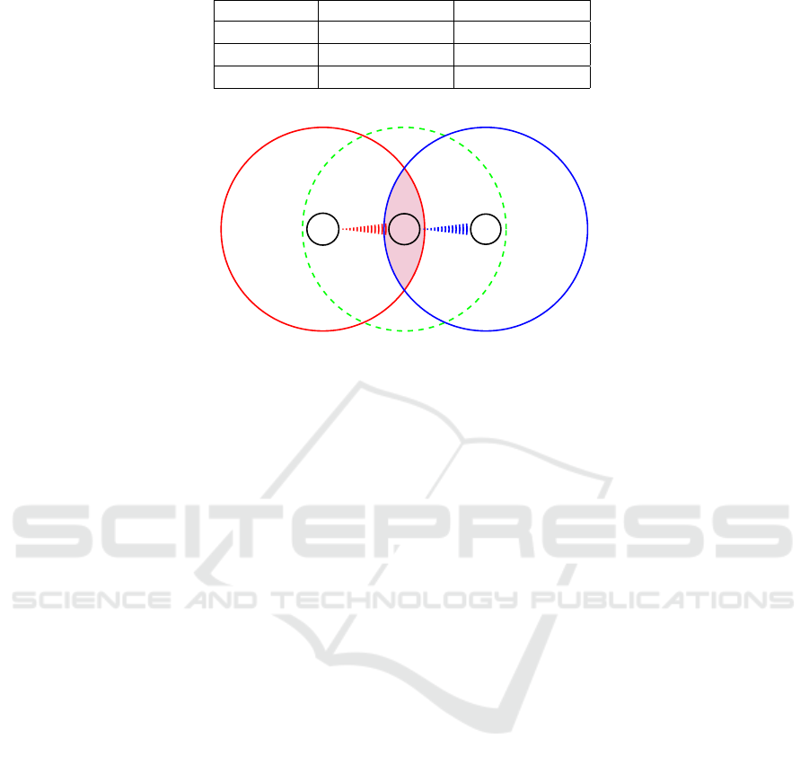
Table 3: Steganographic embedding capacity for typical MORE settings.
Field size q Capacity in bpb Capacity in bpo
2
8
8.γ
2
0.8
2
16
16.γ
2
1.6
2
32
32.γ
2
3.2
C
1
C
2
C
3
A
B
J
Figure 2: A’s, B’s and J’s transmission ranges.
M
T
=
m
4
m
5
m
6
m
1
.m
4
m
1
.m
5
+ m
7
m
1
.m
6
+ m
8
m
2
.m
4
m
2
.m
5
+ m
3
.m
7
m
2
.m
6
+ m
3
.m
8
+ m
9
(14)
U =
m
4
m
5
m
6
0 m
7
m
8
0 0 m
9
(13)
Then the constructed transfer matrix M
T
= LU be-
comes as in (14), where all arithmetic operations are
performed over F
2
8
.
The node B as stated previously, must be in A’s
transmission range for the decoding process:
• The node B as a next-hop forwarder or/and recei-
ver, waits until it receives the whole 3 innovative
combinations, then reassembles the transfer ma-
trix M
T
.
• The node B decomposes M
T
as LU , using algo-
rithm 3, then retrieves the array of secret blocks
S = Concat
R
l
(L),R
u
(U)
via the algorithms 4
and 5 described above.
Where again, matrices L and U are the resulting LU
decomposition via Algorithm 3.
A hides in this scheme, 9 blocks of bits in one ba-
tch transmission process, i.e. the embedding capaci-
ties in this setting is
3
2
spb = 72 bpb. (15)
0.1 spo = 0.8 bpo. (16)
3.4 Steganalysis Perspective
When attacking a steganographic protocol, we have
to distinguish between different scenarios (Kaur et al.,
2015).
If the presence of a steganographic protocol and
its header structure and functionality are known to the
adversary, it is easy to detect the covert communica-
tion. However, if the adversary have no knowledge
of the protocol, and only knows its existence, he can
inject random noise, or reverse engineer the proto-
col. On another hand, if the protocol is known but
not detected, a blind attack can be performed, by sen-
ding disruptive commands to terminate the commu-
nication. And finally, if the adversary has no infor-
mation at all, then no specific attack on the stegano-
graphic scheme is possible.
Studying possible attacks on our technique is
beyond the scope this paper. Nevertheless, at a first
see, the only attacks that could break this stegano-
graphic scheme, since it profits of the random pro-
perty of MORE, are statistical attacks, and precisely
the two-samples Kolmogorov-Smirnov (KS) test (Jus-
tel et al., 1997).
Suppose X = [X
1
,X
2
,...,X
γ
2
] to be a series of
random variables with values x
1
,x
2
,...,x
γ
2
.
The two-samples KS test verifies the hypothesis
that two samples are drawn from the same distribu-
tion. A low KS test statistic means that the distributi-
ons are similar, whereas a high KS test statistic means
the distributions are different.
KS test is applicable to a variety of types of data
with different distributions.
Let F(x) be the empirical cumulative distribution
SECRYPT 2018 - International Conference on Security and Cryptography
96

Table 4: Embedding capacity comparison with some NS techniques.
Channel Covert Used carrier Embedding capacity in bps
WLAN/HW
IEEE 802.11 Cyclic prefix
(Grabski and Szczypiorski, 2013)
3:25 M (BSPK), 6:5 M (QPSK),
13:0 M (16-QAM), and 19:5 M (64-QAM)
WLAN/HW
IEEE 802.11 FCF
(Kr
¨
atzer et al., 2006)
16,8
WLAN/HW
IEEE 802.11
(Szczypiorski, 2003)
216K
WLAN/HW
IEEE 802.11 Padding
(Szczypiorski and Mazurczyk, 2016)
1.1M for data frames, 0.44M for ACKs
Network/SS
VoIP stream payload
(Mazurczyk et al., 2014)
32K
WLAN/HW
IEEE 802.11
MORE’s transfer matrix (Present scheme)
~640M (800M Hz Celeron)
function of X. The KS test statistic for two empirical
distribution functions F
1
(x) and F
2
(x) is :
D
KS
= sup
x
|F
1
(x) − F
2
(x)| (17)
where sup
x
is the the least upper bound of the set
of distances, and for i = 1,2. :
F
i
(x) =
1
γ
2
γ
2
∑
i=1
x
i
≤x
. (18)
Where we denote by
E
, the indicator function of
some event E.
Hence, an attacker who knows the MORE pro-
tocol and its headers structures, observes different
samples of MORE’s batch transmission, then collects
their transfer matrices and tests them via KS will pro-
bably find a high statistic.
As stated above, the existence of hidden data can
be detected, and the system confronted to passive
and/or active statistical attacks. However, the high
embedding capacity of the scheme allows to send γ
2
secret packets in each batch transmission of γ packets
and hence, it is possible to counter the statistical at-
tacks by using a non-uniformly agreed up on batch
transmission phases to send the secret data.
Besides, NC techniques are a relatively new para-
digm in network communications, the covert channel
proposed here is new to the steganalysis research field
and to our knowledge till now, there is no proposition
of steganographic techniques for NC or RLNC as far
as we know.
3.5 Efficiency Comparison
Using the proposed steganographic protocol for bat-
ches of size γ, allows to hide γ
2
symbols in each trans-
mission phase.
Thus the embedding capacity of this scheme is γ
times greater than MORE’s bandwidth (i.e. γ packet
per transmission phase).
And taking into account the machines characteris-
tics used for the implementation (i.e. 800M Hz Ce-
leron (2.2.2)), the embedding capacity in bits per se-
cond for a field size q = 2
8
can reach ~640M bps.
Furthermore, in opposite to other steganographic
schemes, there is no altered information packets in
our protocol since we embed the secret data in the
transfer matrix, for which the coefficients are rand-
omly picked in the first place as explained in (2.2.2).
Hence in this case, there is no distortion issue.
In Table 4, we give some NS protocols, mostly
WLANs related, and their associated embedding ca-
pacity in bps.
4 CONCLUSION
In this paper, we have introduced steganography for
RLNC implementations in wireless networks, by pro-
posing a new distortion-less network steganographic
scheme for MORE. We have shown how effective the
proposed scheme is in term of embedding capacity,
and briefly discussed how statistical attacks against
the protocol can be countered thanks to its high per-
formance. We look forward for upcoming works, re-
garding perspectives of steganography for this new
network communication technique and its new defi-
ned channels.
REFERENCES
Aguayo, D., Bicket, J. C., Biswas, S., Judd, G., and Mor-
ris, R. T. (2004). Link-level measurements from
an 802.11b mesh network. In Proceedings of the
ACM SIGCOMM 2004 Conference on Applications,
Technologies, Architectures, and Protocols for Com-
puter Communication, August 30 - September 3, 2004,
Portland, Oregon, USA, pages 121–132.
A Steganogaphic Scheme for MAC-Independent Opportunistic Routing and Encoding (MORE) Protocol
97

Ahlswede, R., Cai, N., Li, S. R., and Yeung, R. W. (2000).
Network information flow. IEEE Trans. Information
Theory, 46(4):1204–1216.
Bender, W., Gruhl, D., Morimoto, N., and Lu, A. (1996).
Techniques for data hiding. IBM Systems Journal,
35(3/4):313–336.
Bierbrauer, J. and Fridrich, J. J. (2008). Constructing good
covering codes for applications in steganography.
Trans. Data Hiding and Multimedia Security, 3:1–22.
Biswas, S. and Morris, R. T. (2004). Opportunistic routing
in multi-hop wireless networks. Computer Communi-
cation Review, 34(1):69–74.
Chachulski, S., Jennings, M., Katti, S., and Katabi, D.
(2007). Trading structure for randomness in wire-
less opportunistic routing. In Proceedings of the
ACM SIGCOMM 2007 Conference on Applications,
Technologies, Architectures, and Protocols for Com-
puter Communications, Kyoto, Japan, August 27-31,
2007, pages 169–180.
Couto, D. S. J. D., Aguayo, D., Bicket, J. C., and Morris,
R. T. (2003). A high-throughput path metric for multi-
hop wireless routing. In Proceedings of the Ninth An-
nual International Conference on Mobile Computing
and Networking, MOBICOM 2003, 2003, San Diego,
CA, USA, September 14-19, 2003, pages 134–146.
Gentle, J. E. (2012). Numerical linear algebra for applicati-
ons in statistics. Springer Science & Business Media,
2012.
G
´
omez, D., Garrido, P., Rodr
´
ıguez, E., Ag
¨
uero, R., and
Mu
˜
noz, L. (2014). Enhanced opportunistic random
linear source/network coding with cross-layer techni-
ques over wireless mesh networks. In 2014 IFIP Wi-
reless Days, WD 2014, Rio de Janeiro, Brazil, Novem-
ber 12-14, 2014, pages 1–4.
Grabski, S. and Szczypiorski, K. (2013). Steganography
in OFDM symbols of fast IEEE 802.11n networks.
In 2013 IEEE Symposium on Security and Privacy
Workshops, San Francisco, CA, USA, May 23-24,
2013, pages 158–164.
Ho, T., Koetter, R., Medard, M., Karger, D. R., and Ef-
fros, M. (2003). The benefits of coding over routing
in a randomized setting. IEEE Int. Symp. Information
Theory, page 442.
Horn, R. A. and Johnson, C. R. (1994). Topics in matrix
analysis. Cambridge University Press.
Jankowski, B., Mazurczyk, W., and Szczypiorski, K.
(2013). Padsteg: introducing inter-protocol stega-
nography. Telecommunication Systems, 52(2):1101–
1111.
Justel, A., Pe
˜
na, D., and Zamar, R. (1997). A multivariate
kolmogorov-smirnov test of goodness of fit. Statistics
& Probability Letters, 35(3):251–259.
Kaur, J., Wendzel, S., and Meier, M. (2015). Counter-
measures for covert channel-internal control proto-
cols. In Availability, Reliability and Security (ARES),
2015 10th International Conference on, pages 422–
428. IEEE.
Koetter, R. and M
´
edard, M. (2003). An algebraic ap-
proach to network coding. IEEE/ACM Trans. Netw.,
11(5):782–795.
Kr
¨
atzer, C., Dittmann, J., Lang, A., and K
¨
uhne, T. (2006).
WLAN steganography: a first practical review. In Pro-
ceedings of the 8th workshop on Multimedia & Secu-
rity, MM&Sec 2006, Geneva, Switzerland, September
26-27, 2006, pages 17–22.
Kundur, D. and Ahsan, K. (2003). Practical internet stega-
nography: data hiding in IP. Proc. Texas wksp. secu-
rity of information systems.
Li, S. R., Yeung, R. W., and Cai, N. (2003). Linear network
coding. IEEE Trans. Information Theory, 49(2):371–
381.
Mazurczyk, W. and Caviglione, L. (2015). Stegano-
graphy in modern smartphones and mitigation techni-
ques. IEEE Communications Surveys and Tutorials,
17(1):334–357.
Mazurczyk, W., Smolarczyk, M., and Szczypiorski, K.
(2011). Retransmission steganography and its de-
tection. Soft Comput., 15(3):505–515.
Mazurczyk, W., Szaga, P., and Szczypiorski, K. (2014).
Using transcoding for hidden communication in IP te-
lephony. Multimedia Tools Appl., 70(3):2139–2165.
Mazurczyk, W. and Szczypiorski, K. (2008). Covert chan-
nels in sip for voip signalling. In Global e-security,
pages 65–72. Springer.
Pahlevani, P., Lucani, D. E., Pedersen, M. V., and Fitzek,
F. H. P. (2013). Playncool: Opportunistic network co-
ding for local optimization of routing in wireless mesh
networks. In Workshops Proceedings of the Global
Communications Conference, GLOBECOM 2013, At-
lanta, GA, USA, December 9-13, 2013, pages 812–
817.
Pandi, S., Fitzek, F. H., Pihl, J., Pedersen, M. V., and Lu-
cani, D. (2015). Sending policies in dynamic wireless
mesh using network coding. In European Wireless
2015; 21th European Wireless Conference; Procee-
dings of, pages 1–7.
Sundararajan, J. K., Shah, D., M
´
edard, M., Mitzenmacher,
M., and Barros, J. (2009). Network coding meets
TCP. In INFOCOM 2009. 28th IEEE Internatio-
nal Conference on Computer Communications, Joint
Conference of the IEEE Computer and Communicati-
ons Societies, 19-25 April 2009, Rio de Janeiro, Bra-
zil, pages 280–288.
Szczypiorski, K. (2003). Steganography in TCP/IP net-
works. In State of the Art and a Proposal of a New
System–HICCUPS, Institute of Telecommunications’
seminar, Warsaw University of Technology, Poland.
Szczypiorski, K. and Mazurczyk, W. (2016). Stegano-
graphy in IEEE 802.11 OFDM symbols. Security and
Communication Networks, 9(2):118–129.
Van Horenbeeck, M. (2006). Deception on the network:
thinking differently about covert channels.
Wendzel, S., Zander, S., Fechner, B., and Herdin, C.
(2015). Pattern-based survey and categorization of
network covert channel techniques. ACM Comput.
Surv., 47(3):50:1–50:26.
SECRYPT 2018 - International Conference on Security and Cryptography
98
