
Multiple Collision Avoidance between Human Limbs and Robot
Links Algorithm in Collaborative Tasks
Leonardo Sabatino Scimmi, Matteo Melchiorre, Stefano Mauro and Stefano Pastorelli
Department of Mechanical and Aerospace Engineering, Politecnico di Torino, C.so Duca degli Abruzzi 24, Turin, Italy
Keywords: Collaborative Robotics, Artificial Potentials, Collision Avoidance Algorithm, Trajectory Planning.
Abstract: In this paper a real-time collision avoidance approach useful for human-robot interaction was presented and
tested. This approach is based on a collision avoidance algorithm and a distance calculation algorithm. The
collision avoidance algorithm was developed to avoid possible collisions between the upper part of the human
body and the links of the robot. The positions of 25 characteristic points of the body of the human operator
are acquired by two vision sensors. The distances between the robot and the operator are evaluated with the
proposed distance calculation algorithm. These algorithms permit a real-time control of a collaborative robot.
The collision avoidance approach was tested with two kinds of experiments. The results of the tests are
presented.
1 INTRODUCTION
Collaborative robotics is becoming a more and more
interesting topic. It implies the removal of the fences
that divide the working area of the industrial robots
from that of human operators. In this way humans and
robots can share the same workspace and they can
also perform shared tasks. The idea behind the
collaborative robotics is to simultaneously take
advantage of the superior performances of the robot
in terms of precision, repeatability, speed and payload
and of the adaptability of a human operator (Borzelli
et al., 2017; Spada et al., 2017).
Several European projects have analysed the
potentialities and the problems related to the
collaborative robotics, as the SAPHARI project, that
faced the problems related to the safety of the human
operators, or the ROBO-PARTNER project, that
studied the collaboration between humans and robots
in operations of logistical support and inline
assembly.
In these years, some collaborative robotics
applications appeared in industries. In the BMW
factory in Spartanburg (USA), UR robots are used for
sealing of car doors against noise and water
infiltrations and the human operators check the
quality of the operations performed by the robots.
This work considers a case in which a human
operator and a robot share the same workspace, but
they carry out different tasks. So, it is crucial to
analyse the issue of the safety of the human operator.
In fact, it is fundamental that the robot doesn’t hurt
the operator during the operations. To avoid any
unintentional contact between robot and human,
several collision avoidance algorithms have been
developed in the last decades. The collision
avoidance topic was firstly introduced in (Khatib,
1986). In this work the author introduced the
collision avoidance method through artificial
potentials. The idea is to associate an attractive
potential field to the target of the robot and repulsive
potential fields to the sources of danger, that can be
generic obstacles in the workspace or human
operators. This approach was applied in different
forms, (Lacevic et al., 2008; Polverini et al., 2014;
Polverini et al., 2017; Flacco et al., 2012; Flacco et
al., 2015; Mauro et al., 2017; Mauro et al., 2018). In
this work a collision avoidance algorithm based on
the artificial potentials method that permits to
prevent any unintentional contacts between all the
moving parts of the robot and the upper part of a
human operator is presented.
In the collision avoidance scenario, a key factor
is the determination of the position of the obstacles.
In (Polverini et al., 2017; Flacco et al., 2015; Mauro
et al., 2018) vision sensors have been used for this
purpose. In (Takeda et al., 2014; Agostini et al.,
2017) the human tracking was performed using
wearable sensors This methodology avoids
occlusions that can occur with vision systems.
Scimmi, L., Melchiorre, M., Mauro, S. and Pastorelli, S.
Multiple Collision Avoidance between Human Limbs and Robot Links Algorithm in Collaborative Tasks.
DOI: 10.5220/0006852202910298
In Proceedings of the 15th International Conference on Informatics in Control, Automation and Robotics (ICINCO 2018) - Volume 2, pages 291-298
ISBN: 978-989-758-321-6
Copyright © 2018 by SCITEPRESS – Science and Technology Publications, Lda. All rights reserved
291
However, the positioning of sensors on the human is
required. The Microsoft Kinect
TM
v1 and v2 were
widely used as vision sensors, because they have an
accurate depth camera and can estimate the spatial
positions of characteristics points of a human being.
The authors have used two Kinect v2 to determinate
the position of the human being, to overcome the
problems related to the occlusions of the sensors.
The position of the obstacles is a crucial
information for the calculation of the distances
between the robot and the obstacles (in this work
case, between the robot and the human operator). In
different papers (Fischer et al., 2009; Pan et al, 2013;
Fetzner et al., 2014; Kaldestad et al., 2014) the
distance calculations are based on a heavy and time-
consuming reconstruction of the space acquired by
different vision sensors. In this work the authors
have developed a distance calculation algorithm that
is easy to implement and doesn’t need a powerful
hardware for the scene reconstruction.
The paper is organized as follows. The reference
layout is described in Sect. 2. The planned trajectory
is analysed in Sect. 3. The distance calculation
algorithm and the problems related to movement
acquisition are discussed in Sect. 4 and in Sect. 5 the
collision avoidance algorithm is described. The test
to perform and the results are described and
discussed in Sect. 6. The conclusions of this paper
are presented in Sect. 7.
2 HRI LAYOUT
This work considers a case study in which a human
operator and a robot share the same workspace and
perform different tasks. The operator is sitting in
front of a table, where the robot is positioned on. The
idea is to recreate an industrial scenario in which the
operator is building a mechanical component and the
robot is performing another task. In the real
industrial case, the operator wears a coverall. In this
case study, it is possible that the human operator is
near the robot and cross the path that the robot has
to follow. The safety of the operator must be
guaranteed.
To study this problem, the authors developed a
simulated layout in the V-REP environment and a
model of the robot in the MathWorks environment.
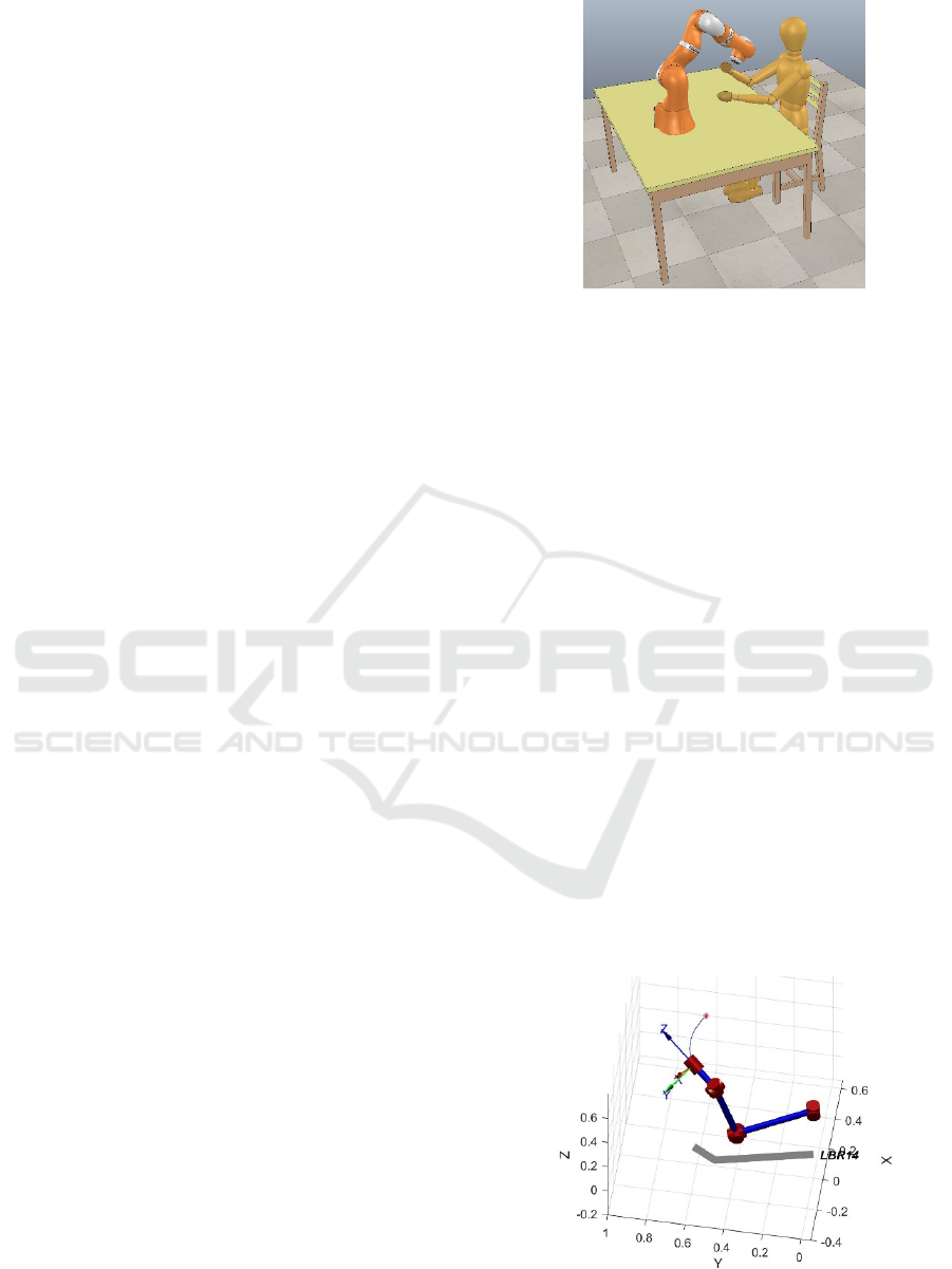
The layout in V-REP can be seen in Figure 1.
Figure 1: Layout of the human-robot interaction case
developed in V-REP.
The position of the operator is acquired by two
Microsoft Kinect
TM
devices and the dummy in V-
REP is moved using the information about spatial
positions of characteristic joints of the human body.
The communication between MathWorks
environment, used for the calculation part, and V-
REP is performed by RemoteAPI functions.
The kinematic layout of KUKA LBR iiwa was
considered as a reference robot. The issue of the
redundancy of the robot was not faced and the third
joint was blocked so to work with a standard
anthropomorphic manipulator.
In the real case, the algorithms described in this
paper will run on a PC that communicates with the
controller of the robot.
3 TRAJECTORY
The task that the robot must carry out is to follow a
planned trajectory. In Figure 2 the curved path that
the end-effector has to follow is shown. The stick
diagram of the robot was obtained with the Corke
Robotics Toolbox (Corke, 2017).
Figure 2: In blue the path that the robot has to follow, in red
the initial position of the end-effector.
ICINCO 2018 - 15th International Conference on Informatics in Control, Automation and Robotics
292

The final and initial pose of the end-effector are
0
,
=
0.25 −0.866 0.433 0.3524
0.433 0.5 0.75 0.6105
−0.866 0 0.5 0.5779
0001
0
,
=
0.25 −0.866 0.433 −0.0476
0.433 0.5 0.75 0.6105
−0.866 0 0.5 0.6779
0001
The robot has to perform this path in 15 s.
4 DISTANCE CALCULATION
ALGORITHM
The estimation of the position of the human operator
and the calculation of the distance between the robot
and the operator are fundamental steps in the collision
avoidance scenario.
In this work, the Microsoft Kinect
TM
v2 was used
to estimate the position of the operator. It gives the
spatial coordinates of 25 joints of a skeleton
associated to the human being.
An important problem is the occlusion of the
cameras. In the case of the Microsoft Kinect
TM
, the
occlusions of the device can determinate an erroneous
estimation of the joints position or a complete loss of
this kind of information. To avoid this problem two
or more Kinect are usually used (Lenz et al., 2012;
Yeung et al., 2013; Moon et al., 2016). In these
papers, the spatial information given by the Kinect
devices are opportunely combined and an optimal
skeleton is obtained. The authors developed an
algorithm that executes the merger of the skeletons
given by two Kinect v2. This algorithm performs this
operation in 4 ms. The analysis of the skeletons
merging algorithm will be carried out in another
paper.
Another crucial element to face is the accuracy of
the determination of the position of the human joints
performed by the Microsoft Kinect
TM
v2. Several
papers (Zennaro et al. 2015; Otte et al. 2016) report
the results of tests conducted to determinate the
precision of such sensor. The reported averaged
errors for the upper part of the human body are 50
mm, so this kind of sensor is acceptable for the
purpose of this work.
The Kinect v2 works with a frequency of 30 Hz.
Therefore, it is essential, in order to have a collision
avoidance real-time strategy, to perform in 33 ms the
merging of the skeletons of the two Kinects, to
estimate the distances between the robot and the
human operator, to calculate the collision avoidance
terms and to send this information to the controller of
the robot. Considering 4 ms for the skeletons
merging, 8 ms for the communication between the
external PC and the robot, the distance calculation
and the collision avoidance algorithms must perform
the necessary calculations in not more than 21 ms.
The distance calculation algorithm is the bottleneck
in this kind of control, while the collision avoidance
algorithm calculates the joint velocities in 2 ms. The
authors developed a distance calculation algorithm
that is easy to implement and can gives all the useful
distances in not more than 9 ms, so to obtain a real-
time control for the robot. The logic of the distance
calculation algorithm is explained in the remaining
part of this section.
The robot is on a table and the operator is sitting
in front of it, so the parts of the human being that the
robot can hit are the torso, the head and the arms. For
this reason, only the joints of the upper body are
considered in the following. In Figure 3 red dots
represent the Kinect points. The points on the human
body are divided into eight parts, that are reported
with dashed lines in Figure 3. Extra markers are
assumed as middle points for each body segments
(black dots in Figure 3).
Figure 3: Points considered for the distances calculation and
the eight parts in which they are divided (dashed lines). In
red the points obtained with the Kinect, in black the extra
points considered by the authors.
On the robot side, nine points are considered for
the distance calculation algorithm. These points are
positioned in the joints centers and in the middle point
between each couple of joints. No points have been
considered for the base and the first link of the robot,
because they have a limited or an absent capability of
motion. The points are divided in three sets. The first
four points (the first one is the middle point between
the second and the third joint, the fourth point is the
center of the fourth joint) are in the first set, called
“L1”. The second four points are in the “L2” set.
Finally, the last point is the end effector, “EE” set.
This division is necessary for the proper application
of the collision avoidance algorithm, as it will be
explained later.
Multiple Collision Avoidance between Human Limbs and Robot Links Algorithm in Collaborative Tasks
293
After the acquisition of the position of the human
body joints and the calculation of the position of the
points of the robot, the distances between each part of
the robot and each part of the human are computed.
To explain the calculation of the distances, a generic
human part h and a generic robot part r are
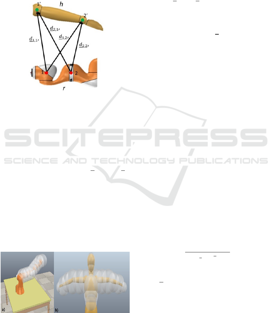
considered, as can be seen in Figure 4.
Figure 4: Determination of the distances between the r part
of the robot and the h part for the human, with two points
of interest for each one.
The algorithm calculates the distance vector
between each point of h and each point of r and then
calculate the vector with the minimum norm among
them. This distance vector will be then considered as
the characteristic distance of the couple h – r.
The results of the distance calculation for the set i
of the robot are vectors in a matrix
,
∗
, where
,
∗
is the distance vector, i is one of the robot set and j is
the index related to the eight parts of the human body,
numbered as in in Figure 3.
These distances are simple point to point distances
and they don’t consider the geometry of the robot and
the dimensions of the human body. To introduce these
elements, the authors considered the points of the
robot and the ones of the human body as centres of
spheres that cover the links of the robot and the parts
of the human body. In Figure 5 the spheres of robot
and human body are shown.
Figure 5: a) spheres centred in the points of the robots; b)
spheres centred in the points of the human body.
The norm of the distances reported in the matrices
previously seen are then subtracted by the radii of the
spheres. The expression of the norm of the distances
considering the radii of the spheres are reported
below
,
=
,
∗
−
−
(1)
where
is the radius of the spheres of the robot and
is the radius of the spheres of the eight parts of the
human body. These distances
,
are then used by the
collision avoidance algorithm.
5 COLLISION AVOIDANCE
ALGORITHM
The distances previously calculated are fundamental
elements of the collision avoidance algorithm. The
algorithm was developed considering the three sets in
which the robot was divided. The algorithm will be
explained considering each single part of the robot
and then how the algorithm influences the motion of
the robot and modifies the planned trajectory.
5.1 Robot Set L1
The set L1 consists of the first four, starting from the
middle point between the second joint and the third.
This part has a reduced possibility of motion
because it has only two joints, since the third joint is
blocked. In this case the algorithm works in order to
reduce the maximum velocities of the first two joints
as the distance between L1 and the human being
became smaller. For this set, the collision avoidance
algorithm works with the minimum distance between
L1 and the operator.
To reduce the maximum velocities, a factor f is
calculated. The equation of f is
f =
,
(2)
where
,
is the minimum distance between L1 and
the human operator, is a reference distance and is
a shape factor. In Figure 6 the factor f versus the
distance is reported.
ICINCO 2018 - 15th International Conference on Informatics in Control, Automation and Robotics
294
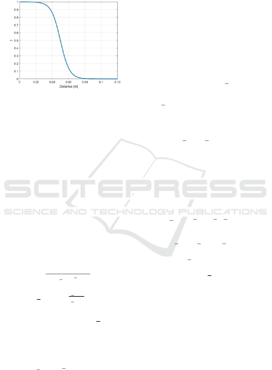
Figure 6: The factor f versus distance with equal to 0.1m
and equal to 9.
The chosen values are = 0.1 m and = 9.
The factor f is then used to reduce the maximum
velocity for the two joints in this way
,,
= ±
,
(1 - f)
(3)
where
,
is the velocity limit for the joint i and
,,
is the new limit, considering the distance
between L1 and the operator.
5.2 Robot Set L2
The set L2 consists of the second four points, from
the middle point between the fourth and the fifth joint
to the wrist center point.
As for L1, the algorithm considers the minimum
distance between L2 and the human body. In this case
the collision avoidance algorithm is different respect
to L1. In fact, the algorithm calculates a repulsive
velocity that pushes away the robot from the obstacle,
avoiding a possible collision.
The equation of this velocity is
=
,
(4)
,
=
,
,
(5)
as in (Flacco et al., 2012), where
is the
maximum admissible velocity and
,
is the
minimum distance.
To convert this velocity in the operative space to
velocities in the joint space, the partial Jacobian
related to the point of L2 of minimum distance is
calculated:
=
∙
,
(6)
In fact, the distance calculation algorithm
determinates the minimum distance between L2 and
the human body and calculates also which of the
points of L2 is the one involved. This point is
essential for the calculation of the Jacobian
.
5.3 Robot Set EE
The set EE consists of the last point on the robot, that
is the end-effector of the robot.
In this case, all the distances are used, not only the
minimum one. For each distance
,
the algorithm
calculates the repulsive velocity with the same
expression of the equation (4) and (5), obtaining
several
,
.
The repulsive velocities calculated for each
distance are then added up to obtain the repulsive
velocity vector
=
∑
,
(7)
5.4 Modified Trajectory
The repulsive velocities calculated for L2 and EE and
the factor f of L1 are then used to modify the planned
trajectory of the robot so to avoid collisions between
robot and operator.
In fact, the inverse kinematics algorithm is
modified in this way
=
∙
++
(8)
(1:3)=
(
1:3
)
+
(9)
The velocities
in (8) permit to avoid collisions
between the end-effector and the human operator,
instead the contribution of
in (9) takes account of
the collision avoidance between L2 and the robot.
The factor f, as seen in 5.1, modifies the maximum
velocities of the first two joints. The approach
developed in this work provides to stop the entire
robot if the values of f is bigger than 0.8. This is a
threshold value when a collision between the robot
and the operator is not avoidable and stop the robot is
the last resort.
The robot is stopped also when the distance
between L2 and the operator or between EE and the
operator is ≤ 0.05 m.
Multiple Collision Avoidance between Human Limbs and Robot Links Algorithm in Collaborative Tasks
295
6 TESTS
Two tests have been conducted to show the
effectiveness of the on-line developed algorithms. In
the first one the human operator moves his right hand
near the EE and the L2 sets of the robot. In the second
test, the hand is near the set L1. In both cases the
human was acquired with two Kinect and the robot
was controlled considering the optimal human
skeleton.
6.1 Test 1
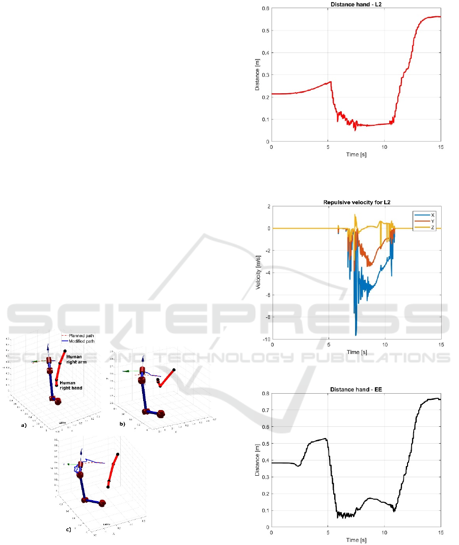
In Figure 7 three frames related to the test 1 are
shown. In Figure 7a), the robot can follow the planned
path because the operator is outside the safety
volume. In Figure 7b), the operator moves his hand
near the L2 and the EE sets of the robot and the
collision avoidance algorithm generates the joints
velocities necessary to modify the trajectory of the
end-effector and avoid any contact. In Figure 8, 9, 10
and 11 it is possible to notice the time interval in
which the hand of the operator is near the robot and
the repulsive velocities are not null. In Figure 7c) the
operator withdraws the hand and the robot can return
to follow the planned path reaching at the end its final
destination.
Figure 7: a) the robot follows the planned path because the
operator is not near; b) the operator puts the hand inside the
safety volume and the robot reacts to that action; c) the
operator is far and the robot is able to reach the desired
destination.
Figure 8: Distance between the hand of the operator and the
L2 set of the robot.
Figure 9: Repulsive velocity for L2.
Figure 10: Distance between the hand and the set EE.
ICINCO 2018 - 15th International Conference on Informatics in Control, Automation and Robotics
296
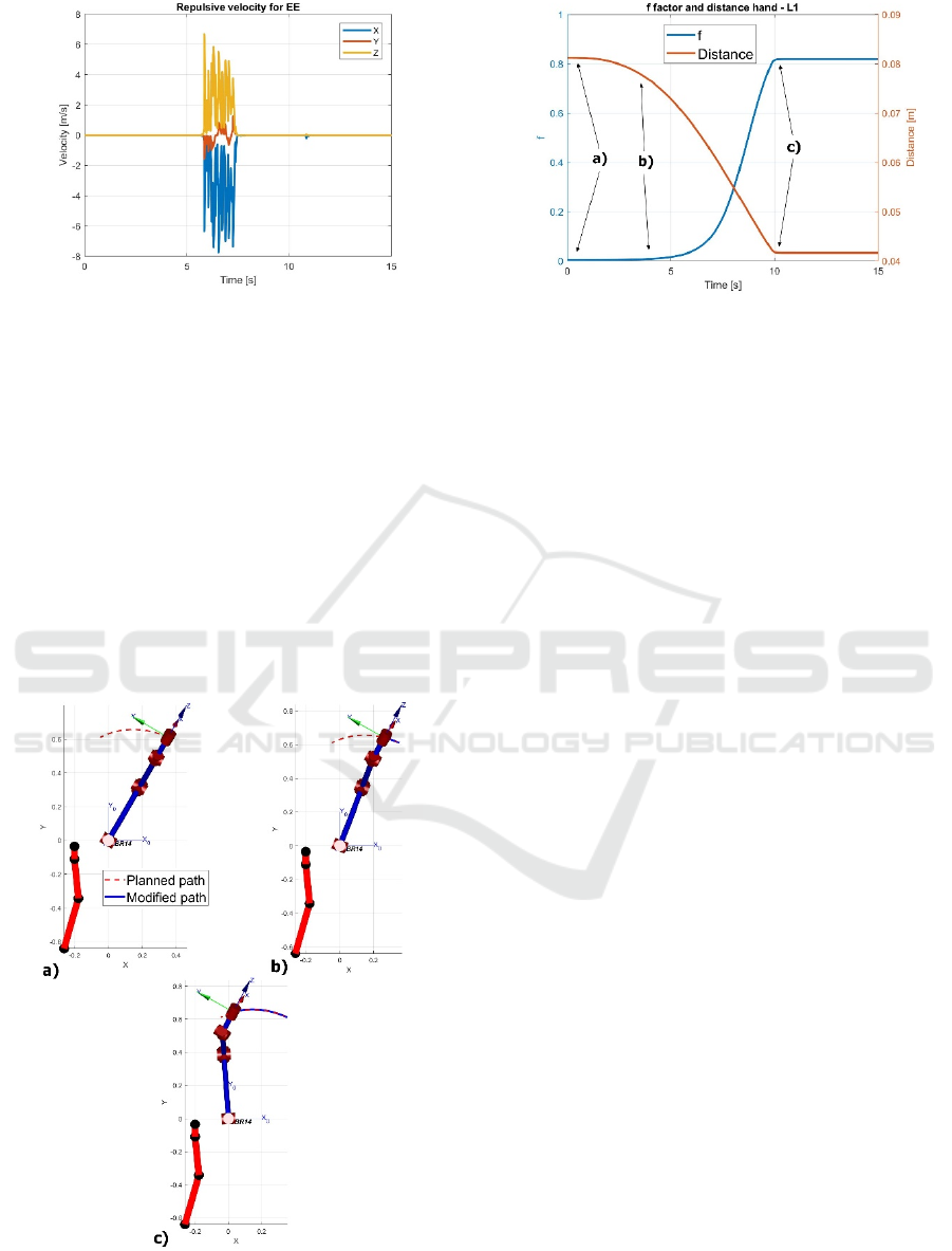
Figure 11: Repulsive velocity for EE.
6.2 Test 2
Three frames related to the test 2 are reported in
Figure 12 with an upper side view, and the
corresponding factor f (in blue) is shown in Figure 13.
In Figure 12a), the robot is far from the operator and
the factor f is equal to 0. In Figure 12b) the hand of
the operator is inside the safety volume and f
increases its value. In Figure 12c) the robot stops its
motion because f is bigger than 0.8. Figure 13 shows
also the distance between the set L1 and the hand of
the operator. It can be clearly visible when the robot
stops and the distance becomes constant.
Figure 12: a) the hand of the operator is outside the safety
volume; b) the hand enters in the volume and f increases its
value; c) f is bigger than 0.8 and the robot stops.
Figure 13: The f factor and distance between the hand and
the part L1 of the robot versus time in the case of Test 2.
7 CONCLUSIONS
In this paper a collision avoidance algorithm was
presented and tested in a simulation environment. The
algorithm permits to modify the planned trajectory of
a robot and to avoid undesired collisions against a
human operator. This algorithm considers possible
collision with six of the eight links of the robot. 21
points on the human body and 9 on the robot were
considered to estimate the distances between the
operator and the robot.
Two different kind of tests were performed to study
the capabilities of the collision avoidance algorithm.
In the first one, the hand of the human operator was
near the L2 and the EE sets of the robot, in the second
one the hand is near the base of the robot. In both
cases, the algorithm modified the planned trajectory
and avoids possible collisions between human and
robot.
Future works will involve the study of the redundancy
of 7 axes robot and the potentialities of the null space
of the Jacobian for the collision avoidance.
REFERENCES
http://www.saphari.eu/
http://www.robo-partner.eu/
https://www.technologyreview.com/s/518661/smart-
robots-can-now-work-right-next-to-auto-workers/
http://www.coppeliarobotics.com/
https://it.mathworks.com/
Agostini, V., Gastaldi, L., Rosso, V., Knaflitz, M., Tadano,
S., 2017. A wearable magneto-inertial system for gait
analysis (H-gait): Validation on normalweight and
overweight/obese young healthy adults. In Sensors,
17(10), 2406.
Multiple Collision Avoidance between Human Limbs and Robot Links Algorithm in Collaborative Tasks
297

Borzelli, D., Pastorelli, S., Gastaldi, L., 2017. Elbow
musculoskeletal model for industrial exoskeleton with
modulated impedance based on operator’s arm
stiffness. In Int. J. of Automation Technology,
11(3):442-449.
Corke, P.I., 2017.Robotics, Vision & Control: Fundamental
Algorithms in MATLAB, Springer. London, 2
nd
edition.
Fetzner, A., Frese, C., and Frey, C., 2014. A 3D
Representation of Obstacles in the Robot’s Reachable
Area Considering Occlusions. In Proceedings 41
st
Int.
Symp. Robot., 2014: 1–8.
Fischer, M., and Henrich, D., 2009. Surveillance of Robots
using Multiple Colour or Depth Cameras with
Distributed Processin. In Proceedings 3rd ACM/IEEE
Int. Conf. Distrib. Smart Cameras, 2009: 1–8.
Flacco, F., Kröger, T., Luca, A.D., and Khatib, O., 2012. A
depth space approach to human–robot collision
avoidance. In IEEE International Conference on
Robotics and Automation, pages 338–345.
Flacco, F., Kröger, T., Luca, A.D., and Khatib, O., 2015. A
depth space approach for evaluating distance to objects.
In J. Intell. Robot. Syst., 80 (1):7–22.
Kaldestad, K.B., Haddadin, S., Belder, R., Hovland, G., and
Anisi, D.A., 2014. Collision Avoidance with Potential
Fields Based on Parallel Processing of 3D-Point Cloud
Data on the GP. In Proceedings IEEE Int. Conf. Robot.
Autom., 2014: 3250–3257.
Khatib, O., 1986. Real-time obstacle avoidance for
manipulators and mobile robots. In Int. J. of Robotics
Research, 5(1):90–98.
Lacevic, B., and Rocco, P., 2010. Kinetostatic danger field
- a novel safety assessment for human-robot interaction.
In IEEE/RSJ International Conference on Intelligent
Robots and Systems (IROS), pages 2169 –2174.
Lenz, C., Grimm, M., R
der, T., and Knoll, A., 2012.
Fusing multiple Kinects to survey shared Human-
Robot-Workspaces. In Technical Report TUM-I1214,
Technische Universität München.
Mauro, S., Pastorelli, S., and Scimmi, L.S., 2017. Collision
Avoidance Algorithm for Collaborative Robotics. In
Int. J. of Automation Technology, 11(3):481-489.
Mauro, S., Scimmi, L.S., and Pastorelli, S., 2018. Collision
Avoidance Systems for Collaborative Robotics. In
Mechanisms and Machine Science, 49:344:352.
Moon, S., Park, Y., Ko, D.W., and Suh, I.H., 2016. Multiple
Kinect Sensor Fusion for Human Skeleton Tracking
Using Kalman Filtering. In International Journal of
Advanced Robotic Systems, 13(2): 65 1-10.
Otte, K., Kayser, B., Mansow-Model, S., Verrel, J., Paul,
F., Brandt, A.U., and Schmitz-Hbsch, T., 2016.
Accuracy and Reliability of the Kinect Version 2 for
Clinical Measurement of Motor Function. In PLoS
ONE, 11(11):1-17.
Pan, J., Şucan, I.A., Chitta, S., and Manocha, D., 2013.
Real-time Collision Detection and Distance
Computation on Point Cloud Sensor Data. In
Proceedings IEEE Int. Conf. Robot. Autom., 2013:
3593–3599.
Parigi Polverini, M., Zanchettin, A.M., and Rocco, P.,
2014. Real-time collision avoidance in human–robot
interaction based on kinetostatic safety field. In
IEEE/RSJ International Conference on Intelligent
Robots and Systems, pages 4136–4141.
Parigi Polverini, M., Zanchettin, A.M., and Rocco, P.,
2017. A computationally ecient safety assessment for
collaborative robotics applications. In Robotics and
Computer – Integrated Manifacturing,
46:4136–4141.
Spada, S., Ghibaudo, L., Gilotta, S., Gastaldi, L., Cavatorta,
M.P., 2017. Investigation into the Applicability of a
Passive Upper-limb Exoskeleton in Automotive
Industry. In Procedia Manufacturing, 11:1255-1262.
Takeda, R., Lisco, G., Fujisawa, T., Gastaldi, L., Tohyama,
H., and Tadano, S., 2014. Drift removal for improving
the accuracy of gait parameters using wearable sensor
systems. In Sensors, 14(12):23230-23247.
Yeung, K.Y., Kwok, T.H., and Wnag, C., 2014. Improved
Skeleton Tracking by Duplex Kinects: A Practical
Approach for Real-Time Applications. In Journal of
Computing and Information Science in Engineering
13(4): 041007-1 - 041007-10.
Zennaro, S., Munaro, M., Milano, S., Zanuttigh, P.,
Bernardi, A., Ghidoni, S., and Menegatti, E., 2015.
Performance Evaluation of the 1st and 2nd Generation
Kinect for Multimedia Applications. In Proceedings -
IEEE International Conference on Multimedia and
Expo, 2015: 1-6.
ICINCO 2018 - 15th International Conference on Informatics in Control, Automation and Robotics
298
