
Deriving Integrated Software Design Models from BPMN Business
Process Models
Estrela Ferreira Cruz
1,2
and Ant
´
onio Miguel Rosado da Cruz
1,2
1
ARC4DigiT - Applied Research Centre for Digital Transformation, Instituto Polit
´
ecnico de Viana do Castelo, Portugal
2
Centro ALGORITMI, Escola de Engenharia, Universidade do Minho, Guimar
˜
aes, Portugal
Keywords:
Business Process Modelling, BPMN Process Model, Use Case Model, Domain Model, UML, User Interface
Model, Model Transformation.
Abstract:
Business process management focuses its attention on designing, modelling and documenting business pro-
cesses, to describe which activities are performed and the dependencies between them. These business process
models have lots of useful information for starting to develop a supporting software system. This paper pro-
poses a model-driven approach to support the construction of a use case model, an integrated domain model,
and a user interface model, from a set of business process models, comprising all existing information in those
models. The proposed approach obtains a system’s complete use case model, including the identification of
actors, use cases and the corresponding descriptions, and relations between use cases, and between these and
the structural domain classes. The resulting integrated use case and domain models are then further transfor-
med into the system’s default abstract user interface model. A demonstration case is used throughout the paper
as a running example. At the end, conclusions are presented, together with some future research directions.
1 INTRODUCTION
Globalization demands from organizations an increa-
sing interconnectivity and integration. Every organi-
zation needs to be technologically prepared for those
demands. For this, organizations may need to reen-
gineer and digitally transform their business proces-
ses. This may be done for automating activities or
better integrating a company’s processes with those of
its business partners: This business process (BP) in-
teraction may be done by allowing business partners
to interact with the system that supports the process
through a user interface, or by directly integrating sy-
stems of both the company and the business partners.
BPMN (Business Process Modelling Notation), is
a standard modelling language created by OMG that
provides two main types of diagrams (OMG, 2011):
the BPMN Process diagram and the BPMN Colla-
boration diagram. The collaboration diagram allows
an organization to know in detail how it communi-
cates with their business partners. This type of dia-
gram describes how participants coordinate their in-
teraction. The process diagrams define a set of busi-
ness activities carried out by an organization for the
attainment of a goal (product or service). This type of
model describes a BP internal to a specific organiza-
tion (OMG, 2011). It includes the process flow, the
information received, sent and stored, and all resour-
ces involved in the process.
Business process modelling is being increasingly
used by organizations to detect bottlenecks, waste of
time, and deviations and to innovate by simulating
possible improvements to processes (Schmiedel and
vom Brocke, 2015; Meyer et al., 2011).
Software that supports the business must be alig-
ned with the business processes (Giaglis, 2001). The-
refore, it is natural to try an approximation bet-
ween BP modelling and software modelling, especi-
ally those models that are useful in the early phases of
software development. Requirements elicitation typi-
cally is the first phase or activity in a software de-
velopment process and, in this phase, the most use-
ful models for software development are use case and
domain classes models.
An organization’s BP models have lots of useful
information that can be used to create a supporting
software system. Nevertheless, it is important to do
the homework beforehand and distinguish wether the
business processes used represent as-is or to-be pro-
cesses. As-is processes need to the reengineered into
to-be processes, so that all the activities are already
thought out and idealized to be integrated within the
Cruz, E. and Cruz, A.
Deriving Integrated Software Design Models from BPMN Business Process Models.
DOI: 10.5220/0006852005710582
In Proceedings of the 13th International Conference on Software Technologies (ICSOFT 2018), pages 571-582
ISBN: 978-989-758-320-9
Copyright © 2018 by SCITEPRESS – Science and Technology Publications, Lda. All rights reserved
571

software supporting the processes. Reengineering the
business processes and requirements elicitation for
the supporting software system may be done simul-
taneously, and involving the same working teams.
This paper’s main contributions are the presenta-
tion of an approach for deriving use case and domain
models from an organization’s BP models and, from
those, deriving a default abstract user interface model.
The approach for deriving use case models is new,
although some of the rules are based on a previous
approach proposed in (Cruz et al., 2014). This new
approach aggregates the information from several BP
models and generates a use case model that includes
use cases’ relations and descriptions.
The structure of presentation is as follows: In the
next section, previous work that enables the presented
integrated approach is addressed. The paper’s presen-
tation is accompanyed by a running example, which
is presented in section 3. Then, in sections 4 and 5,
the approach for deriving use case and domain mo-
dels from an organization’s BP models is presented.
This is based on previous work by one of the authors,
but use case granularity and associated information
is enhanced so that user interface model generation
is made possible. Section 6 addresses the integration
between use case and domain models. User Interface
model generation is presented in section 7. Section
2.2 presents related work and section 8 concludes the
paper and presents some ideas for future work.
2 BACKGROUND AND WORK
RELATED
2.1 Previous Work
An approach to generate a use case model (UCM) ba-
sed on a BP model has been presented in (Cruz et al.,
2014). In the proposed approach, an activity in the bu-
siness process corresponds to a use case (UC) in the
UCM. A participant, represented as a pool or lane, ge-
nerates an actor in the UCM. An actor is related with
UCs generated from the activities represented inside
the pools or lanes associated with the participant that
gave origin to that actor. This same approach also
generates UC descriptions, by transforming BP ele-
ments and their associated information in a control-
led set of sentences in Natural Language (Cruz et al.,
2014).
In (Cruz et al., 2015a) the same authors proposed
an approach to gather in one UCM all the information
existing in a set of BP models. The proposed appro-
ach organizes the UCM in a form of pyramid, with
several different levels of abstraction. The first (top)
level has one UCM where a BP is represented as a
UC. The other levels have several UC models, each
one resulting from the transformation of a BP model.
To generate a complete business processes’ sup-
porting software system, one will need to consider,
not only BP models, but also the collaboration mo-
dels. Though private BP models have information
about who, when and what is performed in a process
inside the organization, the collaboration models al-
lows one to identify what (activities) are executed by
external participants and the information (messages)
exchanged between internal participants and external
participants. Thus, the approach presented here starts
with the selection of the set of business processes that
will be supported by the software under development,
by collecting all private BP models and all collabo-
ration models. This new approach adds to the ones
cited above the identification of all actors involved,
and all UCs related with the corresponding actors, in-
cluding actors derived from external BP participants.
Also, the rules for identifying UCs, from the business
processes, are further refined. The UCM includes the
aggregation of all UCs derived from BP models, in-
terrelating the UCs with include, extend or
enable relations where appropriate.
The same authors also presented an approach that
allows getting a complete domain (data) model by
aggregating all the information about persistent data
that can be extracted from the set of BP models (Cruz
et al., 2015b).
In (da Cruz, 2010; da Cruz, 2015) an approach to
derive a default abstract user interface model as been
proposed. The approach starts from a system’s inte-
grated UC and domain models, and applies a set of
rules for deriving the user interface model. The ap-
proach presented here, refines those rules for allowing
user interface elements to be derived from additional
UC patterns.
2.2 Related Work
It is recognized that the software supporting an or-
ganization’s business processes must be aligned with
these latter. A customized supporting software sy-
stem allows an organization to be more flexible and
prepared to quickly implement necessary changes or
improvements. Thus, several approaches have been
proposed to support the alignment between business
processes and information systems. Some approaches
are focused on the generation of a data model based
on the information existing in business processes, as
is the case of (Samarasinghe and Som
´
e, 2005) and
(Brdjanin et al., 2015). Other approaches try to derive
ICSOFT 2018 - 13th International Conference on Software Technologies
572
UCs from BP models, as is the case of (Rodr
´
ıguez
et al., 2008; Park et al., 2017). Park et. al propose
an approach to derive UCs representing the software
requiremets (Park et al., 2017). The approach derives
the functional and non-functional requirements.
More recently, approaches have been proposed to
generate services based on BP models, as is the case
of (Nikaj et al., 2018). There, the authors propose
a semi-automatic method to derive RESTful services
from process choreographies.
An approach for deriving the UI from BP models
is proposed in (Sousa et al., 2008). It starts by deri-
ving the task model from the BPMN BP model, and
the UI is then derived from the generated task model,
after a task refinement phase. This approach is speci-
ally focused on traceability from BPs to the UI.
In (Dividino et al., 2009) an approach to integrate
the UI with BP models is presented. The approach
extends the BPMN language and the UI dialogue lan-
guage DIAMODL with new components. These ex-
tensions focus mainly in aspects related with commu-
nication and synchronization.
In (Giacomo et al., 2017), the authors propose an
approach to link the information about persistent data
of an organization and BP information to derive exe-
cutable models.
3 RUNNING EXAMPLE
As a running example, a set of four BP models be-
longing to a rent a car firm is going to be used. The
selected business processes are: Book vehicle, Pick-
up vehicle, Drop-off vehicle and Purchase vehicles.
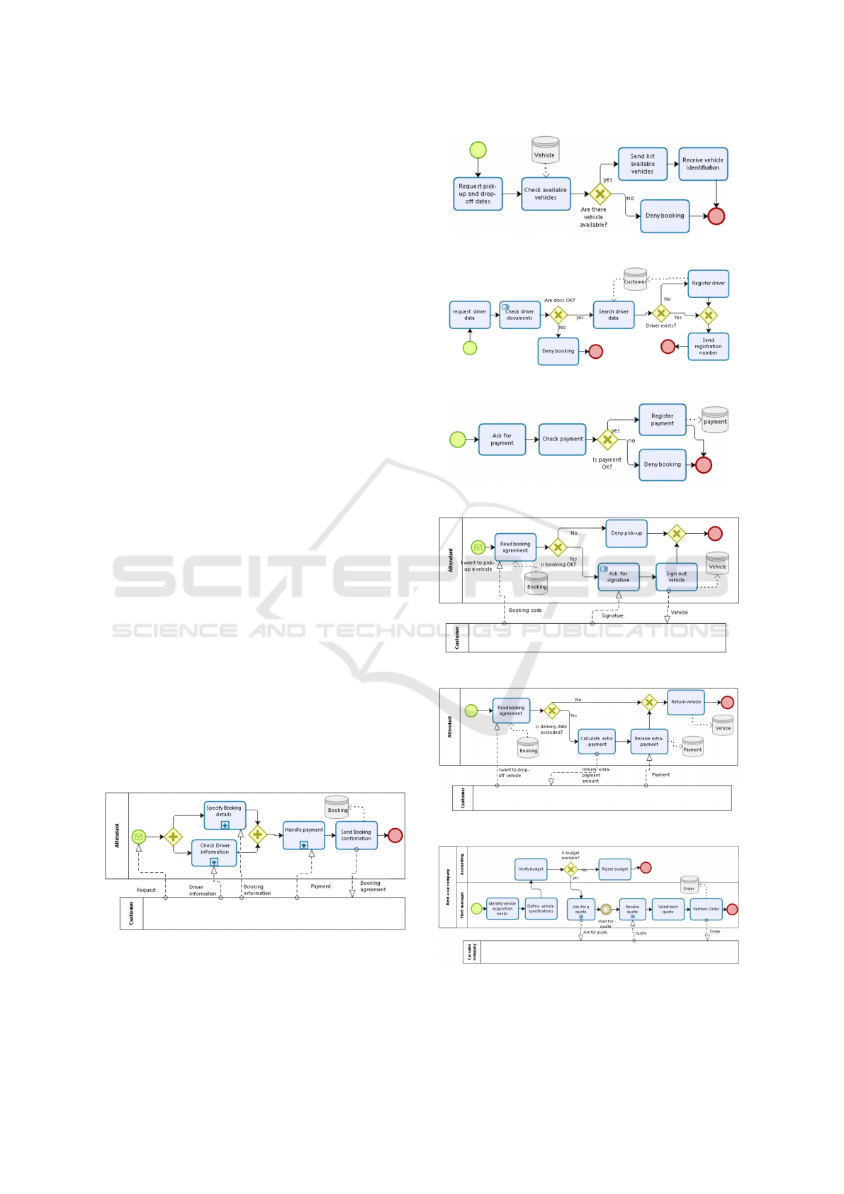
The Book vehicle business process, represented in
Figure 1, has three sub-processes: Specify Booking
details, represented in figure 2; Check and Register
Driver Information (Figure 3) and Handle Payment
(Figure 4).
Figure 1: Book Vehicle business process model.
The BP diagram representing Pick-up Vehicle pro-
cess, is shown in Figure 5. The one for Drop-off Vehi-
cle business process is shown in Figure 6. And, Figure
7 shows the Purchase vehicles business process.
Figure 2: Specify Booking details sub-process.
Figure 3: Check Driver Information sub-process.
Figure 4: Handle Payment sub-process.
Figure 5: Pick-up Vehicle business process model.
Figure 6: Drop-off Vehicle business process model.
Figure 7: Purchase Vehicles business process model.
Deriving Integrated Software Design Models from BPMN Business Process Models
573
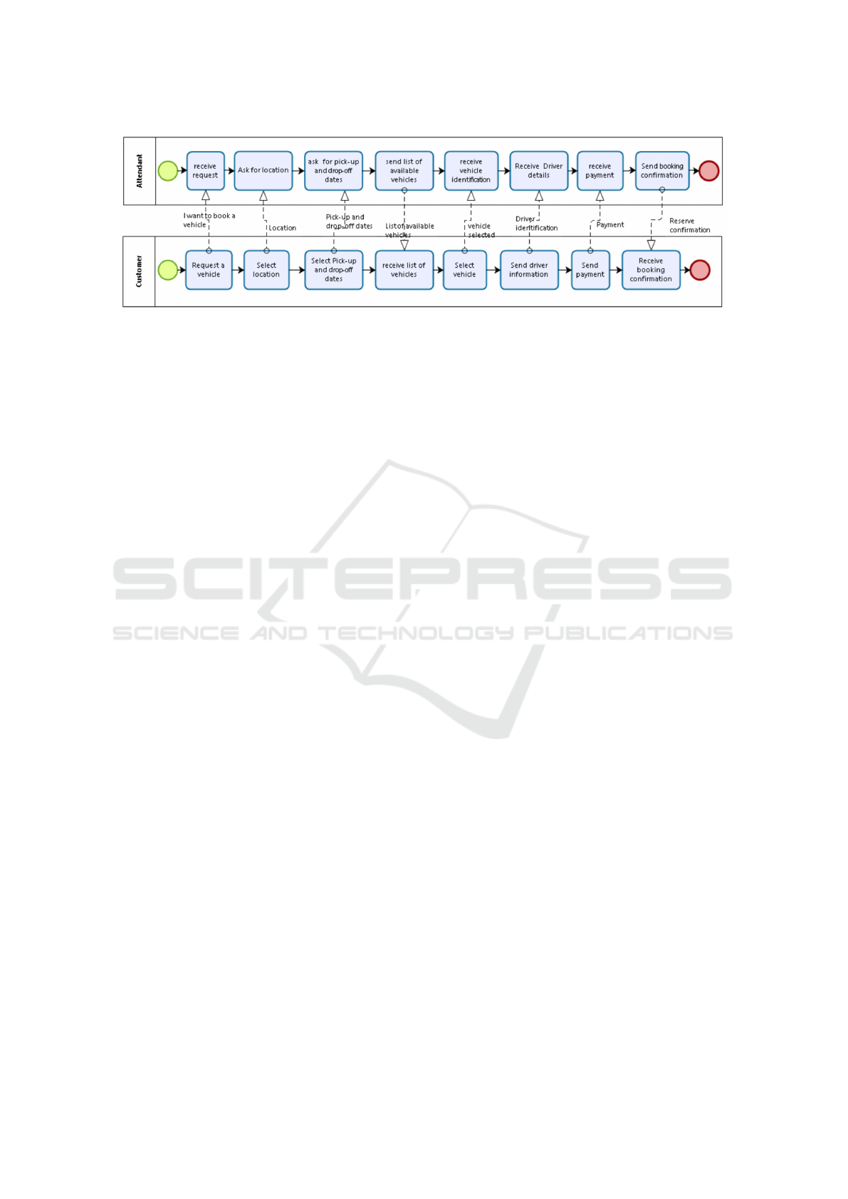
Figure 8: Book a vehicle collaboration process.
The Collaboration process representing the ex-
change of messages between a customer and the or-
ganization to book a vehicle is shown in Figure 8.
4 GENERATING A USE CASE
MODEL
A Use Case Model is used in software development to
model the functionality of a software system. A “use
case is a description of the possible sequences of inte-
ractions between the system under discussion and its
actors, related to a particular goal” (Cockburn, 2001).
Each Use Case has a description of the functionality
that will be built into the proposed system.
An as-is BP diagram represents the present state
of the process in the organization. A to-be BP dia-
gram describes the future state, or how the process
will work once the changes are implemented. Those
changes usually include technological changes. Basi-
cally, when working with as-is processes, it is neces-
sary to identify possible changes that the process will
suffer, like, manual activities that can be automated,
external participants, representing business partners,
that may interact with the system, etc.. In what con-
cerns to the external participants, one needs to iden-
tify how the software system will communicate, or
interact, with them. A participant, may represent an
organization, a role or a software system. When an
external participant represents a software system, usu-
ally the interaction is done through Web Services (Ni-
kaj et al., 2018; ter Hofstede; W.M.P. van der Aalst;,
2006). In the other cases, it will be necessary to create
a user interface to allow the interaction with the busi-
ness partners, if these are to directly use the software
system.
To generate a complete UCM, one needs to iden-
tify: all actors involved; the UCs performed by each
actor; the relations between UCs; and, the use cases’
descriptions and other meta-attributes.
According to UML (Unified Modelling Lan-
guage) (OMG, 2012) UCs can be related through
extend and include relationships. A UC can
include other UCs and can be extended by other UCs.
When a UC is included in a base UC, it means that the
functionality of the included UC is part of the normal
processing of the base UC. A UC may be included by
several UCs, representing that the same functionality
is part of several UCs, helping to reduce duplication
of functionalities by factoring out common behaviour
into use cases that are re-used many times (Jacobson
et al., 1999). A UC may be extended by other UC, ty-
pically when exceptional circumstances are encoun-
tered. An extending UC continues the behaviour of
the base UC every time the extension condition is ful-
filled (Jacobson et al., 1999). An extending UC is an
alternate course of the base UC.
In (da Cruz, 2014) the authors propose new re-
lations between use cases. Among them is the
enable relation, which is a type of relation that
may be defined between two UCs and imposes an or-
der between those UCs’ activities.
4.1 Generating the Use Case Diagram
A set of rules to obtain a UCM based on a set of BP
and collaboration models is presented next. Some of
these rules are based on the ones presented in (Cruz
et al., 2014) and (Cruz et al., 2015b), others are new
rules that extend or refine the former.
R1: An internal BP participant gives origin to an actor
in the UCM.
When developing software to support the busi-
ness processes of a specific organization, one needs
to know which user profiles should be created, and
which functionalities should be made available for
each profile. Some profiles represent participants
internal to an organization (administrator, attendant,
etc.), others may represent business partners who will
have access to the system (for example a customer or
a supplier). A profile is represented by an actor in a
UCM. An actor represents a set of users playing the
same role in the software system having, this way, the
ICSOFT 2018 - 13th International Conference on Software Technologies
574

same set of privileges and access to the same set of
functionalities in the system (Jacobson et al., 1999).
A participant, represented as a pool (or lane) in a
BP model, is responsible for carrying out all activities
represented inside that pool (or lane) (Allweyer, 2010;
OMG, 2011). So, a participant internal to the organi-
zation that will operate the processes supporting sy-
stem, must be represented as an actor in the UCM,
except when all activities performed by that partici-
pant are manual and are to remain manual.
On our running example, we can identify three ac-
tors: Fleet manager and Accounting from Purchase
vehicles BP model (Figure 7), and Attendant from the
other business processes.
R2: An external participant gives origin to an actor in
the UCM when it has been decided that that business
partner will have access to the software supporting sy-
stem.
Business partners, and the activities executed by
them, are represented in BPMN collaboration models.
If it has been decided that a business partner is going
to interact with the system then it will be necessary to
represent this business partner as an actor in the UCM.
At this software development stage, the stakeholders
are still involved in the software development process
so, it is the correct time to decide, whether or not, the
business partner will interact with the software system
being constructed.
In the rent a car example, two external participants
are involved: Car sales company from Purchase vehi-
cles business process (Figure 7) and Customer from
the other business processes. The stakeholders have
to decide whether and which of the participants will
have access to the software system.
R3: A subdivision of a pool or lane in several la-
nes will be represented by an actors’ hierarchy in the
UCM (Cruz et al., 2014). This subdivision is only
represented in BP models internal to an organization.
In Purchase vehicles business process (Figure 7)
we are able to identify an actors’ hierarchy where
the actors fleet manager and Accounting both descend
from Rent a car company (see Figure 10).
R4: A group of consecutive activities performed
within the same lane gives rise to a use case.
A Use Case represents an interaction session bet-
ween an actor (human or machine) and the software
system (OMG, 2012; Jacobson et al., 1999). A set of
activities performed without interruption in the same
lane, i.e. by the same participant (represented as an
actor), can be performed in a software system session,
so it can be represented as a UC in the UCM. When
the process flows to another lane, another participant
(actor) will perform the activities represented in the
process, it will be executed in another system session,
so these activities must be represented by another UC.
The same may happen when the process is interrupted
by an intermediate event. That means that the acti-
vities executed before and after the event cannot be
executed in the same system session. Consequently,
the set of activities executed before the event may be
grouped in one UC, and the activities executed after
the event must be grouped in another UC.
When all process’s (or sub-process) activities are
executed within the same lane and without interrup-
tion, then the whole process may be represented in
one UC in the UCM. In this case, the name of the
UC may be name of the process (or sub-process). On
the other cases, the UC name must be assigned by the
software engineer.
In Figure 1 we may see that all activities are exe-
cuted in the same pool. So, all activities can be repre-
sented by the same UC (Book vehicle). The UC name
can be the name of the process. In Figure 7 we have
two lanes involved in the process. The first group of
activities are executed in the fleet manager lane, thus,
can be grouped in the same UC (Identify and define
vehicle specification). The second group of activities
are executed in another lane (by accounting actor) so,
are grouped in another UC (Check budget). The rest
of the process is executed in fleet manager lane but the
activities are “interrupted” by a timer event (Wait for
quote), thus the activities performed before and after
the event are group in separated UCs, namely Ask for
quote and Prepare purchase order. The UCM may be
seen in Figure 10.
R5: An atomic activity can also be represented as UC
in the UCM, depending on the nature of the action
performed in the activity (activity’s type).
A Use Case is a single unit of meaningful work
and may be created with a high abstraction level or
with a low abstraction level (Cockburn, 2001).
A BPMN activity is a piece of work performed
during the execution of a Business Process (OMG,
2011). An activity may be atomic, usually represen-
ted as a task, or non-atomic, represented as a sub-
process (OMG, 2011). A task carried out in a pro-
cess can be classified as manual, script, service, etc.
A manual task is a task performed without any in-
formation technology involvement (Allweyer, 2010;
OMG, 2011). Each non-manual activity will be repre-
sented as a UC in the UC diagram. In what concerns
to manual activities, the stakeholders need to discuss
and decide which activities should remain manual and
which activities will be supported by the software sy-
stem. Manual activities that are going to be supported
by the system under development, should be repre-
sented as use cases in the UCM. The name of the UC
is the name of the activity.
Deriving Integrated Software Design Models from BPMN Business Process Models
575
R6: An actor, representing a participant internal to
the organization, is related with all use cases, which
represent groups of activities or atomic activities, per-
formed inside that lane. An actor being related with
a UC means that the actor has access to the functio-
nality represented by the UC. The set of use cases an
actor has access to defines their overall system role
(OMG, 2012). All activities represented in a Lane
are performed by the participant identified in that lane
(OMG, 2011). Consequently, UCs representing those
activities are related with the actor representing that
internal participant.
R7: An actor, representing an external participant, is
related with UCs representing activities with which
the participant exchanges messages.
Decisions about external participants involvement
in the software system may be based on the collabo-
ration model’s information which highlights the acti-
vities executed by external participants.
After the discussion about the external partici-
pants that will interact with the system being deve-
loped, and about manual activities that may have sup-
port in the system, it will be necessary to decide which
processes and activities (represented as UCs) an actor,
representing an external participant, has access to.
In the limit, when all process’ activities exchange
messages with the same external participant, the ex-
ternal participant may substitute the internal partici-
pant (or be added with the same activities) in the pro-
cess. This is the case, in our example, of the Customer
participant in Book vehicle business process.
R8: Use cases may be related to each other by
extend, include or enable relationships
as explained next:
• A UC representing a group of activities is related
with the use cases representing the atomic activi-
ties belonging to that group. If an atomic activity
is mandatory, the UC representing that activity (B)
is included in the UC representing the group (A):
A include B. If the activity (C)is not man-
datory (optional or conditional), the UC represen-
ting the atomic activity extends the UC represen-
ting the group: C extend A.
Optional activities are the ones that can be exe-
cuted, or not, depending on a gateway condition.
Activities that are always executed during the pro-
cess execution, are considered mandatory.
In our example (Figure 7), in Purchase Vehicle
business process, the Identify and define vehicle
specification UC has been identified, through R4,
to represent a group of two mandatory activities,
Identify vehicle acquisition needs and Define vehi-
cle specifications. Each of these activities gives
origin to a UC that is included in the Identify and
define vehicle specification UC.
In sub-process Check Driver information (Figure
3), in the Book Vehicle business process, the acti-
vity Register driver is optional, as the activity is
only executed if the Driver exists? gateway deci-
sion is No. Thus the Register driver UC extends
the Check Driver information UC (Figure 9).
• A UC A is related with a UC B with enable
relationship whenever B can only be executed af-
ter A. For example, in the Purchase Vehicle busi-
ness process, the activity Define vehicle specifica-
tions can only be executed after executing activity
Identify vehicle acquisition needs, thus UC Iden-
tify vehicle acquisition needs enable the UC
Define vehicle specifications (see Figure 10).
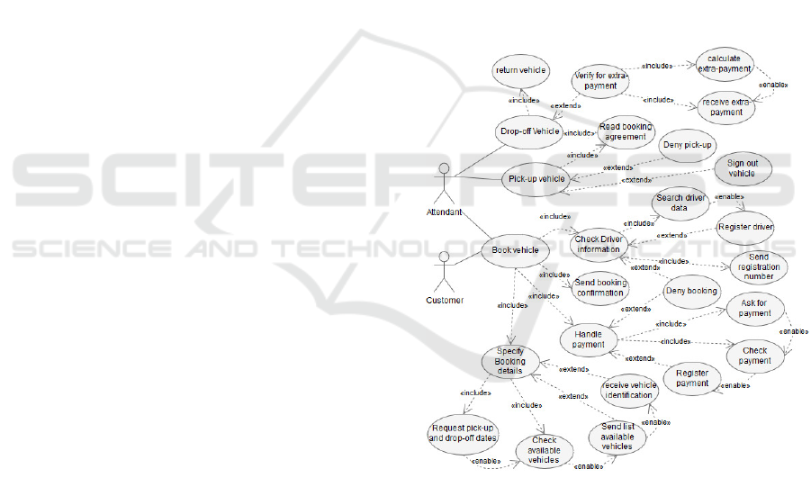
The resulting UCM for Attendant and Customer
actors may be seen in Figure 9, and the resulting UCM
for the Fleet manager and Accounting actors is repre-
sented in Figure 10.
Figure 9: Generated use case model for Attendant and Cus-
tomer actors.
4.2 Generating Use Case Descriptions
In (Cruz et al., 2014) the authors proposed a template
to describe a use case. The template includes the UC’s
name, actor, pre-conditions, post-conditions, trigger
and the main scenario. We decided to use the template
proposed in (Cruz et al., 2014), extending it with two
more fields: entities and operations executed on those
entities (CRUD operations). These two extra fields
help in reinforcing the integration between the UCM
ICSOFT 2018 - 13th International Conference on Software Technologies
576
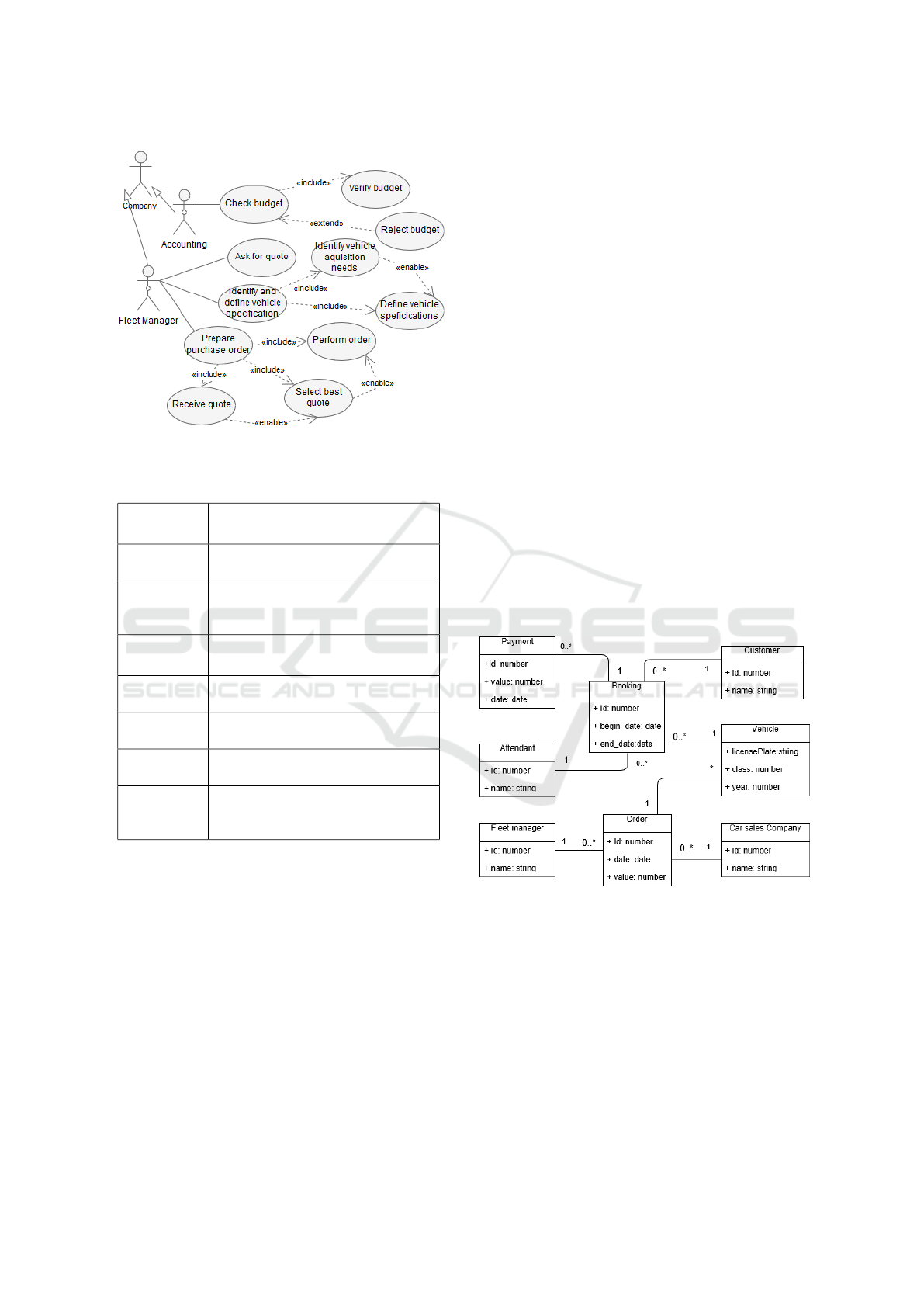
Figure 10: Generated use case model for Fleet manager and
Accounting actors.
Table 1: The template for describing use cases.
Use Case
name
The use case name identifies the goal
as a short active verb phrase.
Actors
List of actors involved in the use case
Pre-
Conditions
Conditions that must hold or represent
things that happened before the use
case starts.
Post-
Conditions
Conditions that must hold at the con-
clusion of the use case.
Trigger
Event that starts the use case.
Entities
Entities stored or retrieved in the use
case.
Operations
Read or write operation from entities.
Scenario
Sequence of interactions describing
what the system must do to move the
process forward.
and the domain model (DM), and are needed for the
ulterior process of user interface (UI) model genera-
tion. The proposed template is composed of the fields
identified and described in Table 1.
When a UC represents an activity, the UC name
may come from the name of the activity. When a UC
represents a group of activities performed sequenti-
ally, the UC name must be assigned by the software
engineer.
The related actors are the ones that represent the
participants responsible for the execution of the acti-
vity, or group of activities, to which the UC traces
back (R6 and R7).
Preconditions are obtained from incoming con-
nections from activity flows and from gateways. Post-
conditions are obtained from the outgoing connecti-
ons from end or throwing events.
Triggers are obtained from the connections co-
ming from start and catching events. All other inco-
ming connections give rise to a phrase that will be
included in the UC scenario.
The entities involved in the UC are derived from
data associations outgoing to, and incoming from,
data stores in the BP diagrams (Cruz et al., 2015b).
The name of the entity is the name of the data store
(Cruz et al., 2015b). An outgoing data association
to a data store means that information is being sto-
red in that data store (represented as an entity in the
domain model) during the activity execution. An in-
coming data association from a data store means that
information is being retrieved from that data store (en-
tity). These two new UC template items are going to
be used in the user interface model generation.
The scenario describes in a controlled natural lan-
guage the interactions within the UC, between the ac-
tor and the system (refer to (Cruz et al., 2014)).
5 GENERATING THE DOMAIN
MODEL
Figure 11: Generated domain model.
A set of rules to generate a domain model (data mo-
del) based in a set of BP models is presented in (Cruz
et al., 2015b). This includes the domain entities, the
relationship between them, including cardinality and
optionality, and entities’ attributes. These rules are
summarized next.
A data store, representing persistent data, gives
origin to an entity in the domain model. The name of
the entity is the name of the data store. A participant
that stores data during a business process execution,
originates an entity in the domain model. Data stores
Deriving Integrated Software Design Models from BPMN Business Process Models
577
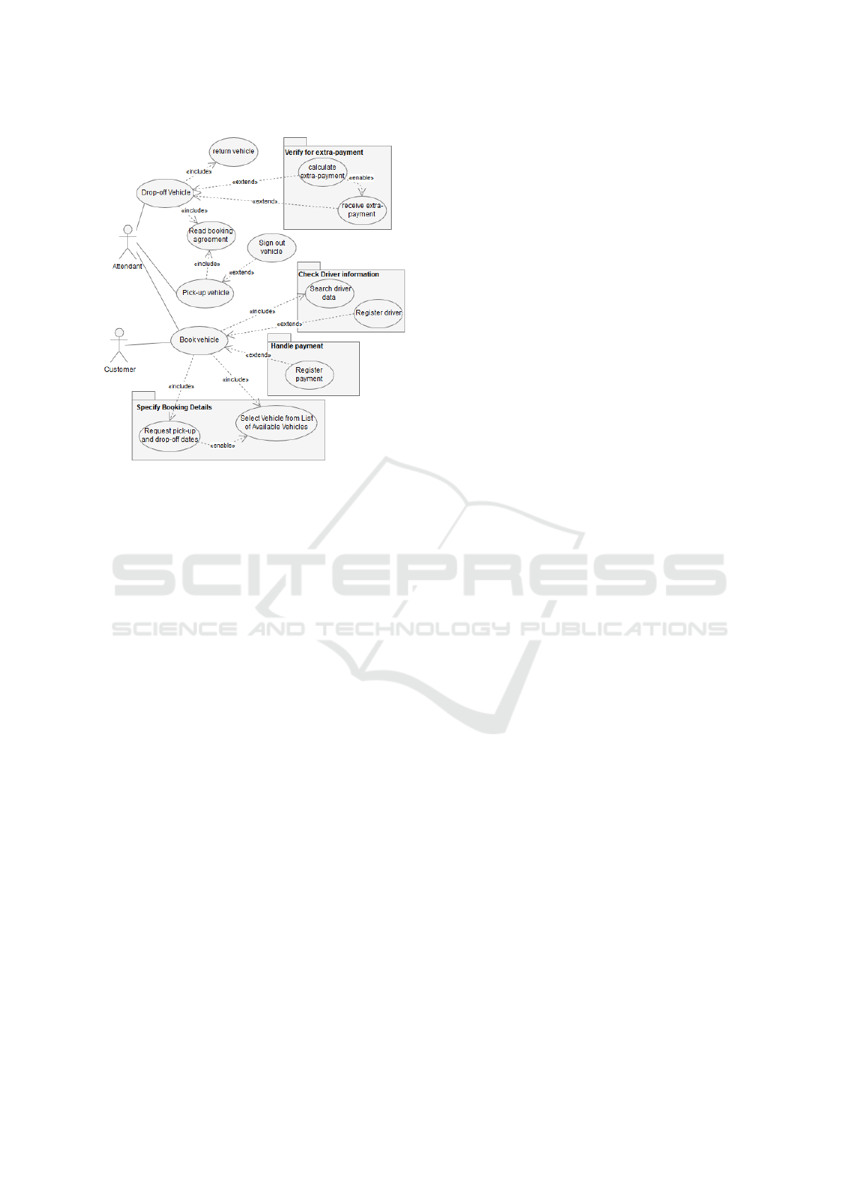
Figure 12: Modified Use Case Model.
and/or participants with the same name are represen-
ted by the same entity.
The relationships between entities are basically
derived from the information exchanged between par-
ticipants and the activities that manipulate the data
stores, and from the information that flows through
the process, as explained in (Cruz et al., 2015b).
By default, the initial attributes of an entity that
represents a participant are id and name (Cruz et al.,
2012). For the entities originated by data stores, the
attributes can be identified in a XML file (since a
data store is an item-aware element). As explained in
(Cruz et al., 2012) each item from a data store is re-
presented as an entity attribute in the domain model.
The details are explained in (Cruz et al., 2015b).
The resulting domain model (DM), from the bu-
siness processes presented in section 3, is shown in
Figure 11. The entities Payment, Booking, Customer,
Vehicle and Order are derived from the data stores
with the same name. The entities Attendant, Custo-
mer, Fleet manager and Car Sales Company are deri-
ved from participants.
Attendant entity is related with Payment, Booking,
Vehicle and Customer because this participant is re-
sponsible for the execution of the activities that store
data in the corresponding data stores. By the same
reason, Fleet manager is related with Order entity.
Customer entity is related with Payment and Book-
ing because the Customer participant sends messages
to the activity that stores information in those data sto-
res. By the same reason, Car Sales Company and Or-
der entities are related.
The relation between entities Order and Vehicle
is derived from a business process that, because of a
matter of space, is not presented in this paper.
Some of the derived relations are redundant, so
the generated domain model needs to be analysed by
a software engineer to detect and eliminate redundant
relations (Cruz et al., 2015b).
6 INTEGRATING THE USE CASE
AND DOMAIN MODELS
As mentioned before, a use case encloses a descrip-
tion of functionality. This description may be at a
higher level of abstraction, closer to the business, or
at a lower level of abstraction, closer to the software
system. UC models directly obtained from BP dia-
grams may include use cases derived from activities
that are done manually in the process. If these activi-
ties are identified as manual, in the BP diagram, then
they can simply be ignored in the UCM derivation
process. But, if those manual activities made their
way to the UCM, then the software engineer needs
to remove them from the UCM. The process descri-
bed in the previous sections yields a domain and a use
case model, which are integrated. Model integration,
between the UCM and the DM, is achieved by having
each UC’s detail reference DM entities and the CRUD
operations made on those entities in the context of the
UC (see columns Entities and Operations in Table 2).
Those UCs that are not associated to executing opera-
tions on DM entity instances, are either manual or UC
packages. The former are simply removed from the
UCM, and the latter are transformed to UC packages
in the final UCM. The association of UCs to opera-
ted domain model entities is a task for the software
engineer, along with other UC model transformati-
ons. Use case model of Figure 9, from our running
example, is then transformed into the one in Figure
12. Note that UC Check available vehicles has been
renamed to Select Vehicle from List of Available Vehi-
cles. The other two that have been removed from the
same package had no entities/operations associated.
7 GENERATING AN
INTEGRATED USER
INTERFACE MODEL
Having generated fully integrated domain and use
case models from the initial BPMN process diagrams,
we are now able to apply a set of rules based on the
transformation process proposed in (da Cruz, 2015).
ICSOFT 2018 - 13th International Conference on Software Technologies
578

Table 2: Partial Use Case Details (Entities and Operations)
according to the defined template.
Use Case name
Entities
Operations
Book Vehicle
Booking Create Booking
Search Driver
Data
Customer
Retrieve and Select
Customer
Register Driver
Customer Create Customer
Register Payment
Payment
Create Payment
Select Vehicle
from List of Avai-
lable Vehicles
Vehicle
(rela-
ted to
Booking)
Retrieve vehicles with
no Booking between
pick-up and drop-off
dates, and Select
Vehicle
Pick-up Vehicle Booking Update Booking
Read Booking
Agreement
Booking Read Booking by ID
Sign-out Vehicle
Vehicle
Update Vehicle
Drop-off Vehicle Booking Update Booking
Return Vehicle Vehicle
Update Vehicle
Receive extra-
payment
Payment
Create Related Pay-
ment
This process is suitable for data oriented applications
and yields a forms-based user interface model (UIM).
The transformation process begins with a system’s
domain and use case models, where for each UC the
entities it manipulates are identified together with the
operations used in that entity objects’ manipulation.
The UIM generation process identifies UC patterns in
the UCM, and applies a set of transformation rules,
which are explained in subsection 7.2.
7.1 UIM Language
The UIM, here derived, follows the UIM metamodel
and concrete language presented in (da Cruz, 2015).
The UIM models a user interface in an abstract plat-
form independent way, meaning that the model ele-
ments do not represent the concrete look and feel of
the user interface, but rather its contents and modeled
behaviour. The UIM concrete notation is based on
Canonical Abstract Prototypes (CAP), proposed by
L. Constantine (Constantine, 2003), for capturing the
presentation aspects of interactive systems. CAP ele-
ments are abstract interaction objects (AIO), which
are UI elements that don’t have a unique concrete
representation. These enable capturing only the ab-
stract presentation aspects of a UI. In (da Cruz, 2015),
CAP elements have been given a semantics, by rela-
ting them with the UI modeling language concepts in
the proposed metamodel. The UIM metamodel defi-
nes the following concepts:
• InteractionSpace (IS): is an abstract UI space
where interaction between a human actor and the
system occurs, in the context of a use case. An IS
is composed of InteractionBlocks, and it may also
contain ActionAIOs and an abstract menu bar,
composed of menus that aggregate menu items,
each one allowing the navigation to another IS.
• InteractionBlock (IB): is associated to an entity
from the DM, and may be optionally associated
to another one (master entity) associated with the
former, enabling master-detail information in an
IS, provided that in the same IS another IB is as-
sociated to the latter entity as its mandatory entity.
An IB may contain DataAIOs and ActionAIOs.
• DataAIO: is an abstract widget for data in-
put/output. It may have a type and may be associ-
ated to properties in the DM entities. A DataAIO
may enable or disable other DataAIOs or Actio-
nAIOs when interacted with.
• ActionAIO: is an abstract widget for navigating to
another IS, triggering operations on the user inter-
face (e.g.: CancelOp), or executing domain ope-
rations, which are behaviors associated to the use
cases whose interactions take place within that IS,
or methods of the domain entities belonging to the
subject of those use cases (e.g.: CRUD operati-
ons). An ActionAIO may enable or disable other
DataAIOs or ActionAIOs when interacted with.
7.2 UIM Generation
The UIM generation process starts with a system’s in-
tegrated domain and use case models. Each UC des-
cribes system functionality, which corresponds to an
operation on a domain entity object. Use cases, and
the associated domain model entities, form patterns,
from which UIM elements may be derived.
The transformation rules, from the domain and
use case models to the UIM, are listed and briefly
explained below. Although most of the rules are
the result of one of the authors’ PhD research work
(da Cruz, 2010), rules UIM03a, UIM06a and UIM12
are completely new.
Rule UIM01: A different initial IS is derived from
each actor in the UCM. This IS gives the actor access
Deriving Integrated Software Design Models from BPMN Business Process Models
579
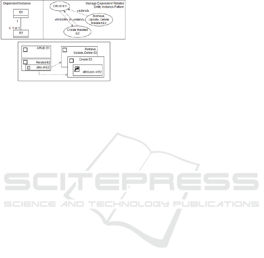
Figure 13: Abstract UIM pattern resulting from the transfor-
mation of the “Manage Dependent Related Entity Instance”
domain and Use Case patterns (taken from (da Cruz, 2015)).
to the interaction spaces derived from the UCs di-
rectly linked to the actor.
Rule UIM02: Transform directly accessible “List
Entity” UCs. Use cases directly linked to an actor,
and that are associated to a “retrieveAll” operation on
an entity type, give origin to an IS that lists objects of
that entity type.
Rule UIM03: Transform directly accessible “Create
Entity” use cases. Directly accessible UCs, from an
actor, that are associated to a “create” operation on an
entity type, give origin to an IS with abstract widgets
(DataAIOs) for entering the attributes’ values and an
ActionAIO (e.g. button) for persisting the created en-
tity object.
Rule UIM03a: Transform directly accessible “Up-
date or Delete Entity” use cases. Directly accessible
UCs, from an actor, that are associated to an “update”
or “delete” operation on an entity type, give origin to
an IS with DataAIOs for entering unique identifier at-
tributes’ values, an ActionAIO for reading the entity
instance by the unique identifier, and an ActionAIO
for updating/deleting the read entity object.
Rule UIM04: Transform “CRUD Entity” use cases,
accessible through an extension. UCs that extend
another UC that sets the context (entity object to be
manipulated), and that are associated to any CRUD
operation on that entity type, give origin to an IS with
DataAIOs for displaying/entering/modifying the attri-
butes’ values and an actionAIO for operating (create,
retrieve, update, delete) the entity object.
Rule UIM05: Transform “List Related Entity” use
cases, accessible through an inclusion or extension.
UCs included in, or that extend, another UC that sets
the context (main entity object), and are associated to
a “retrieveAll” operation on a related entity type, give
origin to an IS that lists objects of that related entity
type that are associated to the main entity object set
by the including UC.
Rule UIM06: Transform “CRUD (one) Related En-
tity Instance” use cases, accessible through an inclu-
sion or extension. UCs included in, or that extend,
another UC that sets the context (main entity object),
that are associated to any CRUD operation on a re-
lated entity type, give origin to an IS with DataAIOs
for displaying/entering/modifying the attributes’ va-
lues and an actionAIO for operating (create, retrieve,
update, delete) the related entity object.
Rule UIM06a: Transform “CRUD (several) Related
Entity Instances” use cases, accessible through an in-
clusion or extension. UCs included in, or that extend,
another UC that sets the context (main entity object),
and are associated to any CRUD operation on a rela-
ted entity type, give origin to an IS that lists objects of
that related entity type that are associated to the main
entity object set by the including UC.
Rule UIM07: Transform “List and Select (one) Re-
lated Entity” UCs, accessible through an inclusion or
extension. UCs included in, or that extend, another
UC that sets the context (main entity object), that are
associated to a link/unlink operation on a related en-
tity type, give origin to an IS that lists objects of that
related entity type, from where one can be selected
for linking to the main entity object.
Rule UIM08: Transform “List and Select and
Link (several) Related Entity” use cases, accessible
through an inclusion or extension. UCs included in,
or that extend, another UC that sets the context (main
entity object), that are associated to a link operation
on a related entity type, give origin to an IS that lists
objects of that related entity type, which can be se-
lected for linking to the main entity object.
Rule UIM09: Transform User defined operation
UCs. This rule derives the IS for UCs associated to
a user defined operation. This is not used in this pa-
per.
Rule UIM10: Transform UC inheritance and speci-
alized use cases, rooted in a directly accessible UC.
This rule derives the IS for UCs that inherit from anot-
her UC. This rule is not used in this paper.
Rule UIM11: Transform enabling, deactivation and
choice UC relations. enable, choice and
deactivate relations between any two UCs are
transformed to preconditions within interaction spa-
ces. For example, an enable relation between
two UCs originates a dependency between the inte-
raction spaces of those UCs, only enabling the target
IS when the source IS has been submitted.
Rule UIM12: Transform UCs that get values for fil-
tering an enabling “List and Select” UC. This UC is
transformed to an IS with DataAIOs for getting the
associated parameters and providing them to the IS of
the enabling UC that will perform the selection. Both
ICSOFT 2018 - 13th International Conference on Software Technologies
580
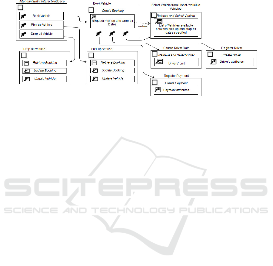
Figure 14: UIM for the rent a car running example.
UCs are included or extend the same base UC. An in-
stance of such UC is ”Request pick-up and drop-off
dates”, from our running example.
Rule UIM13: Transform UCs that perform calculati-
ons for an enabling UC. This UC is transformed to a
function that performs the calculations before provi-
ding the results to the enabling UC. Both UCs are in-
cluded or extend the same base UC. An instance from
our running example, of such UC, is ”Calculate extra-
payment”.
Figure 13 depicts the UIM generated from the
Manage Dependent Related Entity Instance pattern.
Here, rules UIM03 or UIM03a or UIM04 have been
applied together with rule UIM06, which is applied
two times, in order to obtain the associated UIM pat-
tern (da Cruz, 2015).
Figure 14 depicts the UIM generated from the At-
tendant actor and its use cases in the Use Case Model
of our running example. By rule UIM01, an initial
IS is created for the Attendant actor, giving access to
the interaction spaces derived from the actor’s directly
linked use cases, namely Book Vehicle, Pick-up Vehi-
cle and Drop-off Vehicle. By rule UIM03, an IS is
derived from the Book Vehicle UC. By UIM07, an IS
is derived from UC Select Vehicle from List of Avai-
lable Vehicles, and an IS is derived from UC Search
Driver Data. By UIM06, an IS is derived from UC
Register Driver, and an IS is derived from UC Regis-
ter Payment. By UIM03a, an IS is derived from each
UC Pick-up Vehicle and Drop-off Vehicle.
8 CONCLUSIONS
Knowing business processes has been recognized to
help ensuring that the software under development
will realy meet business needs. Some software de-
velopment processes (e.g. Unified Process) already
refer to BP models as a nice-to-have documentation
for the next steps of software development. The ge-
neration of a UCM, including UC’s descriptions, and
an integrated domain model, based on a set of BP mo-
dels ensures the implementation of all requirements
that come directly from the process models. Deriving
a User Interface Model from the use case and dom-
ain models allows to easily prototype the software sy-
stem that supports the processes, helping in further
eliciting and refining requirements, the BP models,
and the derived integrated software models themsel-
ves. All rules for deriving a UCM, DM and UIM from
a set of inter-related business process models can be
automated through appropriate tools, although a soft-
ware engineer intervention is still needed in cases of
ambiguity and for quality assurance of the final result.
Tools for generating a UIM from the UCM and
DM, and for generating a running system prototype
from the integrated UIM and DM have already been
developed (see (da Cruz, 2010) and (Gonc¸alves and
Gonc¸alves, 2016)). Future work will address develo-
ping a tool for partially automating the use case and
domain models generation from the BP models.
Future work will also apply this approach to big-
ger industrial problems.
REFERENCES
Allweyer, T. (2010). BPMN 2.0 - Introduction to the stan-
dard for business process Modeling. Books on De-
mand GmbH, Norderstedt.
Brdjanin, D., Banjac, G., and Maric, S. (2015). Automated
synthesis of initial conceptual database model based
on collaborative business process model. In Bogda-
nova, A. M. and Gjorgjevikj, D., editors, ICT Inno-
vations 2014, volume 311 of Advances in Intelligent
Systems and Computing, pages 145–156. Springer In-
ternational Publishing.
Deriving Integrated Software Design Models from BPMN Business Process Models
581

Cockburn, A. (2001). Writing Effective Use Cases. Addison
Wesley.
Constantine, L. (2003). Canonical abstract prototypes for
abstract visual and interaction design. In J.F. e Cunha,
J.A. Jorge, N. J. N., editor, Proceedings of the DSV-
IS 2003, number 2844 in Lecture Notes in Computer
Science, pages 1–15. Springer-Verlag Berlin Heidel-
berg.
Cruz, E. F., Machado, R. J., and Santos, M. Y. (2012). From
business process modeling to data model: A syste-
matic approach. In QUATIC 2012, Thematic Track
on Quality in ICT Requirements Engineering, IEEE
Computer Society Press, Los Alamitos, California,
U.S.A., pages 205–210. IEEE Compute Society.
Cruz, E. F., Machado, R. J., and Santos, M. Y. (2014). From
business process models to use case models: A syste-
matic approach. In Aveiro, D., Tribolet, J., and Gou-
veia, D., editors, Advances in Enterprise Engineering
VIII, volume 174 of Lecture Notes in Business Infor-
mation Processing, pages 167–181. Springer Interna-
tional Publishing.
Cruz, E. F., Machado, R. J., and Santos, M. Y. (2015a).
Bridging the gap between a set of interrelated business
process models and software models. In 17th Interna-
tional Conference on Enterprise Information Systems,
pages 338–345.
Cruz, E. F., Santos, M. Y., and Machado, R. J. (2015b). De-
riving a data model from a set of interrelated business
process models. In 17th International Conference on
Enterprise Information Systems, pages 49–59.
da Cruz, A. M. R. (2010). Automatic Generation of User
Interfaces from Rigorous Domain and Use Case Mo-
dels. PhD thesis, Faculty of engineering, University
of Porto.
da Cruz, A. M. R. (2014). Refining use cases through
temporal relations. In 2014 9th International Con-
ference on Software Paradigm Trends (ICSOFT-PT),
pages 95–102.
da Cruz, A. M. R. (2015). Use case and user interface pat-
terns for data oriented applications. In Hammoudi,
S., Pires, L. F., Filipe, J., and das Neves, R. C., edi-
tors, Model-Driven Engineering and Software Deve-
lopment, pages 117–133, Cham. Springer Internatio-
nal Publishing.
Dividino, R., Bicer, V., Voigt, K., and Cardoso, J. (2009).
Integrating business process and user interface mo-
dels using a model-driven approach. In 2009 24th In-
ternational Symposium on Computer and Information
Sciences, pages 492–497.
Giacomo, G. D., Oriol, X., Estaol, M., and Teniente, E.
(2017). Linking data and bpmn processes to achieve
executable models. In International Conference on
Advanced Information Systems Engineering.
Giaglis, G. M. (2001). A taxonomy of business process mo-
deling and information systems modeling techniques.
International Journal of Flexible Manufacturing Sys-
tems, 13:209–228.
Gonc¸alves, S. and Gonc¸alves, F. (2016). Am
´
alia code gene-
rator. Technical Report, Polytechnic Institute of Viana
do Castelo (in Portuguese).
Jacobson, I., Booch, G., and Rumbaugh, J. (1999). The Uni-
fied Software Development Process. Addison-Wesley.
Meyer, A., Smirnov, S., and Weske, M. (2011). Data in
business processes. Universit
¨
atsverlag Potsdam.
Nikaj, A., Weske, M., and Mendling, J. (2018). Semi-
automatic derivation of restful choreographies from
business process choreographies. Software & Systems
Modeling.
OMG (2011). Business process model and notation
(BPMN), version 2.0. Technical report, Object Ma-
nagement Group.
OMG (2012). Unified modeling language (OMG UML),
version 2.5. Technical report, Object Management
Group.
Park, G., Fellir, F., Hong, J.-E., Garrido, J. L., Noguera,
M., and Chung, L. (2017). Deriving use cases from
business processes: A goal-oriented transformational
approach. In Proceedings of the Symposium on App-
lied Computing, SAC ’17, pages 1288–1295. ACM.
Rodr
´
ıguez, A., Fern
´
andez-Medina, E., and Piattini, M.
(2008). Towards obtaining analysis-level class and use
case diagrams from business process models. In Ad-
vances in Conceptual Modeling Challenges and Op-
portunities, volume 5232 of Lecture Notes in Compu-
ter Science, pages 103–112. Springer Berlin Heidel-
berg.
Samarasinghe, N. and Som
´
e, S. S. (2005). Generating a
domain model from a use case model. In Intelligent
and adaptive systems and software engineering.
Schmiedel, T. and vom Brocke, J. (2015). Business process
management: Potentials and challenges of driving in-
novation. In vom Brocke, J. and Schmiedel, T., edi-
tors, BPM - Driving Innovation in a Digital World,
Management for Professionals, pages 3–15. Springer
International Publishing.
Sousa, K., Mendonc¸a, H., Vanderdonckt, J., Rogier, E., and
Vandermeulen, J. (2008). User interface derivation
from business processes: A model-driven approach
for organizational engineering. In Proceedings of the
2008 ACM Symposium on Applied Computing, SAC
’08, pages 553–560, New York, NY, USA. ACM.
ter Hofstede; W.M.P. van der Aalst;, C. O. M. D. A. (2006).
From BPMN process models to BPEL web services.
In IEEE International Conference on Web Services
(ICWS’06).
ICSOFT 2018 - 13th International Conference on Software Technologies
582
