
Adapting a Component-based Model Approach to SOA:
A Robotic Experience
Francisca Rosique
1
, Nour Ali
2
and Fernando Losilla
1
1
Universidad Politécnica de Cartagena, Spain
2
University of Brighton, U.K.
Keywords: Real Time (RT), Service Component Architecture (SCA), Service Oriented Architecture (SOA), Component
based Software Engineering (CBSE), Model Driven Software Development (MDSD), Robotic Systems.
Abstract: C-Forge is an approach that combines Component Based Software Engineering (CBSE) and Model Driven
Software Development (MDSD), and has been previously used to define the software architecture of robotic
systems. However, as robotic systems become part of a dynamic and heterogeneous environment, CBSE
becomes limited. A paradigm that promises to easily adapt and integrate collaborative, heterogeneous and
distributed systems is Service Oriented Architecture (SOA). In this paper, we enrich C-Forge with service
oriented architectural primitives by extending its CBSE metamodel and Model Driven Methodology.
1 INTRODUCTION
Technological advances in multiple disciplines such
as telecommunications and informatics have
contributed to the emergence of reactive systems,
especially in the robotic domain. Besides,
improvements in network technologies, particularly
wireless networking, have revolutionized how
robots perceive the environment and interact with it.
Robots can now be connected to different devices
such as mobile phones or sensors, which allows
them to react in real time to events of the rest of the
system. For example, a robot can be controlled
remotely by a mobile user or it can detect an obstacle
and recalculate its path. Robots can also collaborate
in real time, responding to other robots’ tasks such
as movements, trajectories, etc.
These systems have to dynamically integrate and
perform collaborative tasks with diverse devices and
software systems. This change in the nature of
robotic systems enforces the usage of new software
engineering paradigms for their development and
evolution. New developments should provide for
(1) integration between heterogeneous systems,
(2) independence of location, implementation and
usage, (3) reusability, (4) integration with reactive
environments, (5) real time.
The Division of Electronics Engineering and
Systems (División de Sistemas e Ingeniería
Electrónica, DSIE) Research Group has a long
experience in developing software for services
robots, applying different approaches (reference
architectures, Component-based software
engineering (CBSE), and Model Driven Software
Development (MDSD)) (Diego et al., 2010) to cope
with the increasing complexity of new projects since
1999. The DSIE has recently developed C-Forge (C-
Forge, 2015), an Eclipse based Model Driven tool-
chain for supporting a component based
development process. C-Forge has been used in the
last years to implement hybrid robotic architectures
by defining a set of static components that interact
with each other though their ports. It is remarkable
the flexibility and ease to change, at design time, the
kind of components, its ports or interaction
interfaces, as well as the connections between them
and their distribution in different processes, nodes or
concurrent regions. An example of the application
of C-Forge to an Autonomous Underwater Vehicle
is described in (Ortiz et al., 2015).
However, this flexibility in design time is not the
same in run-time. In our experience, there are certain
components that require a static and stable
connection. But as we reach the higher layers, where
components that require some intelligence are, for
example a mission planner, it is highly
recommended to have a reconfiguration capability
comparable to the variability that may occur in the
mission. To adapt to this situations, two possible
ways were detected:
Rosique, F., Ali, N. and Losilla, F.
Adapting a Component-based Model Approach to SOA: A Robotic Experience.
DOI: 10.5220/0006837505570562
In Proceedings of the 13th International Conference on Software Technologies (ICSOFT 2018), pages 557-562
ISBN: 978-989-758-320-9
Copyright © 2018 by SCITEPRESS – Science and Technology Publications, Lda. All rights reserved
557

1. Dynamic reconfiguration, where new links
between components are created when
necessary, for instance when performing system
reconfiguration, which involves the replacement
of components or links. However, this may not
be the optimal solution if we just want to use
temporarily the services offered by other
component.
2. Use Service Oriented Architecture (SOA) to
allow components to look for the run-time
available services that they can use, as well as to
publish their services so that other components
can use them.
In this context, SOA is a paradigm that, even
though is not new, it is becoming increasingly
important as a solution to some of the new
requirements that society imposes on robotic systems.
SOA (Erl, 2008) is especially useful for providing a
solution to the integration, implementation and
location independence of systems. Therefore, we
decided to experiment with a mixed structure where
the components themselves offer services as SOA
architectures. For example, following the case study
presented in (Ortiz et al., 2015), a mission planner
component would create new missions depending on
the available services at the time. In this way, the aim
is to combine the power of a CBSE-MDSD process
with the flexibility of SOA. For this purpose, it is
necessary to extend C-Forge (that initially only
considers a pure CBSE process) so that components
can publish their services and use the services
published by others. In this way, when a component
needs to discover the available services, assuming
that they may change, it could use the services that
have been published by the other components that are
included in the architecture.
The rest of this paper is organized as follows:
Section 2 introduces C-Forge, our previous
experience which has motivated this work. Section 3
describes the SOA adaptation process into C-Forge
and finally Section 4 presents the conclusions and
further work.
2 C-FORGE
C-Forge is a tool-chain developed with the Eclipse
environment that uses its Model Driven Software
Development (MDSD) plugins to provide support for
developing component based applications (Rosique
et al., 2016). C-Forge consists of the following tools:
(1) a language to model component based
applications, called WCOMM, (2) a framework
called FraCC, which provides run-time support for
the applications modeled using WCOMM.
2.1 WCOMM Component Language
A WCOMM component is an entity that encapsulates
its internal state and comprises both structural and
behavioral parts. The structural part is defined by its
ports and the messages that flow through them,
grouped in interfaces. These messages are sent
following the asynchronous no-reply communication
scheme. Behaviour is defined by means of a finite
state machine, similar to the defined in UML,
extended with temporal properties. That is, the user
models the behaviour of the component by means of
states, transitions, events, guards and orthogonal and
hierarchical regions. Each state can have additionaly
an internal activity, which will be later associated
with code in FraCC. WCOMM also models what we
called the the “shell” of the activity, formed by the
messages that are exchanged and the events that are
created. These events, along with the reception of
messages through ports, are responsible for the
change of the component state. Therefore, they
establish the connection between structure and
behavior. Finally, an application is modeled as a set
of components interconnected among them.
2.2 Framework FraCC
FraCC is a component based framework implemented
in C++ that was developed with the purpose of
providing (1) full support to the characteristics of the
WCOMM component model, (2) full control over the
concurrency characteristics of the application, letting
the user decide how many processes and threads will
be created and in which threads the components will
run and (3) explicit control of the assignment of
components to computational nodes. These features
allow the use of FraCC in applications with real-time
constraints.
3 ADAPTING C-FORGE TO SOA
This section briefly describes the main characteristics
of the adaptation process. The first step is adapting
our metamodel, which extends the C-Forge
metamodel (see Figure 1) in order to support SOA
constructs. The second step is to establish the work
methodology.
ICSOFT 2018 - 13th International Conference on Software Technologies
558
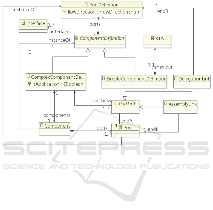
Figure 1: Excerpt of WCOMM metamodel.
3.1 SOA Extended Metamodel
The main idea of the proposal is to integrate SOA (Ali
and Babar, 2009) characteristic concepts by making
use of the previously defined C-Forge artifacts.
Among the most important concepts of the proposal
are Contract and Choreography. In SOA, services
adhere to a communication agreement, which is
defined along with one or more service description
documents. This contract is usually represented by a
sequence diagram. Would it be possible to represent
this contract with other models or diagrams? Our
proposal relies on being able to take advantage of the
elements of the structural notation of the component
model to define this contract, more specifically,
making use of state machines.
In this regard, the SOA concepts as well as the
concepts of the metamodel of the WCOMM
component language (see Figure 1) proposed
previously have been thoroughly studied. Similar
concepts have been found in both approaches
(services, interfaces, ports, etc.). Consequently, the
possibility of defining a SOA architecture from a
WCCOM component model that interrelates services
by means of interfaces and well-defined contracts
between these services has been devised. Interfaces
are defined in a neutral way that must be independent
from the hardware platform, the operating system and
the programming language in which the service is
implemented. This fact allows services, built on
different systems, to interact among them in a
uniform and universal way.
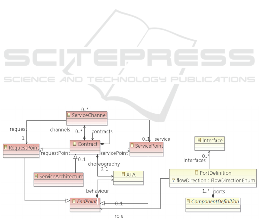
Figure 2 shows, in red color, the SOA concepts
that have been added to C-Forge: Contract,
Choreography, EndPoint, Interface, and
ServiceChannel.
The elements involved in this proposal are:
Component. It retains the elements of the
structural notation defined in our previous
work, differentiating definition from instances
for reutilization purposes. This fact can be
appreciated in the ComponentDefinition and
Component concepts. The Component concept
is directly related with the SOA concept of
Participants and allows to define the service
providers and consumers.
Interface. This concept is common to both
approaches. It describes the operations used
Adapting a Component-based Model Approach to SOA: A Robotic Experience
559
between a service provider and a service
consumer from the perspective of the provider.
EndPoint. Components (Participants) provide
or consume services via the EndPoints. These
EndPoints have a direct correspondence to
what in the original WCOMM metamodel was
called Port. An EndPoint is the part or feature
of a component which acts as the interaction
point for a service – where it is provided or
consumed. When an EndPoint is a provider it
contains at least a ServicePoint. When an
EndPoint is a consumer it contains at least a
RequestPoint.
ServicePoint. A ServicePoint defines a
capability offered by one entity to others.
RequestPoint. A RequestPoint defines the
connection point through which a Participant
makes requests or consumes services. A
participant can be a consumer, a provider or
both.
ServiceChannel. ServiceChannel provide a
communication path between consumer
(RequestsPoint) and provider services
(ServicePoint).
Contract define the terms, conditions,
interfaces and choreography that participants
must agree to. They specify how services are
provided and consumed based on interactions
and behaviors involving the participants
(Components). Each role or party involved in a
Contract is defined by an Interface or
Interfaces, which denotes the type of the role.
A Contract is a binding contract – binding on
any participant that has a service port typed by
a role (EndPoint) in a service contract. It
defines the relationships between a set of roles
defined by Interfaces.
Choreography. An important part of the
Contract is the choreography. The
choreography is a specification of what is
transmitted and when it is transmitted between
parties to enact a service exchange. The
choreography specifies exchanges between the
parties – the data, assets and obligations
between the parties. The choreography defines
what happens between the provider and
consumer participants without defining their
internal processes – their internal processes do
have to be compatible with their Contracts. A
Contract Choreography is a diagram behavior
usually defined by an interaction diagram or
activity diagram. In this approach the
choreography is specified by an Extended
Timed Automata (extended state machine)
represented as XTA element in the metamodel.
ServiceArchitecture. It consists in the
interaction of different service provider and
consumer roles (contracts and participants) to
achieve a goal. Because of this, a collaboration
model is used to represent it.
Figure 2: Excerpt of metamodel, focused on its SOA concepts (elements highlighted in red).
ICSOFT 2018 - 13th International Conference on Software Technologies
560
3.2 Work Methodology: Case Study
In order to demonstrate the new proposal, a simple
case study based on an oceanographic system has
been carried out. The system is composed of a series
of smart buoys deployed in a marine environment, a
small AUV (Autonomous Underwater Vehicle) and a
landside central control office in charge of managing
and planning the missions of the AUV. The main
mission of the AUV consists in traversing the seafloor
gathering data and sending them to the central office.
Buoys also collect and send data. In addition, they
also send emergency reports when necessary
(atmospheric and maritime phenomena, etc.). Finally,
the central office receives all the data in real time and,
whenever it is necessary, it sends a mission update
command to the UAV (go back to the meeting point,
change a route in search of new data, etc.).
Considering this study case, we will perform some
steps that will allow us to devise the architecture of
the system. When creating a ServicesArchitecture by
using the top-down design approach, it is important
to think about the problem that is being solved or
what you are attempting to accomplish. The steps are
the following:
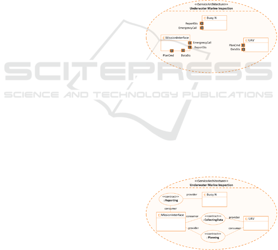
1. Identify the mission/goal of the robotic system.
In this first step, the main mission of the system
must be identified and assigned as
“ServiceArchitecture”. In our study case, the
main goal of the system is underwater marine
inspection and this goal is used as the name of the
“ServiceArchitecture” (Underwater Marine
Inspection), as can be seen in the upper part of
Figure 3. In the following steps, the next roles
involved in the architecture (ServiceContract and
Participants) will be identified, as well as the
composite services in which these roles
participate.
2. Identify Participants of the Architecture. In this
step the participants (components) are added to
the architecture. These are represented as parts or
roles in the service architecture. We choose a set
of components from our initial component based
architecture as participants. Participants are
components that participate in the service
architecture providing/requiring services. In our
case, they are: “UAV”, “Buoy1/
Buoy2/…BuoyN/” and “MissionInterface”.
These components correspond to complex high-
level components but, in order not to increase the
complexity of the case study, we will not go into
more detail with them (the component diagram
corresponding to the UAV component in this
example can be seen with greater detail in (Ortiz
et al., 2015)).
3. Define RequestPoint and ServicePoint. Once the
participants are identified, it is necessary to
define which EndPoints (ports) are involved in
the architecture. This is required in order to be
able to define a Contract in the following steps.
It is also necessary to indicate the type of the
EndPoints (RequestPoint or ServicePoint). The
more precise this step is, the easier it will be to
define the contract. To this effect, step 3 must be
complemented by step 4. The EndPoints used in
the case study are “PlanCmd”, “ReportSts”,
“EmergencyCall” y “DataSts”. In Figure 3 it can
be observed how they are distributed among the
different participants.
Figure 3: Architecture, participants and endpoints
definition.
4. Define Service Interfaces of the EndPoint. In this
step the ServiceInterfaces of each component are
defined.
5. Specify Service Contract. We define the service
contract from the point of view of the service
providers. The service contracts define the roles
of the service provider and service consumer.
The service provider indicates the choreography
of the messages and the rules for the provision of
a service that the consumer has to fulfil.
Figure 4: Architecture view including contracts and
participants.
Adapting a Component-based Model Approach to SOA: A Robotic Experience
561
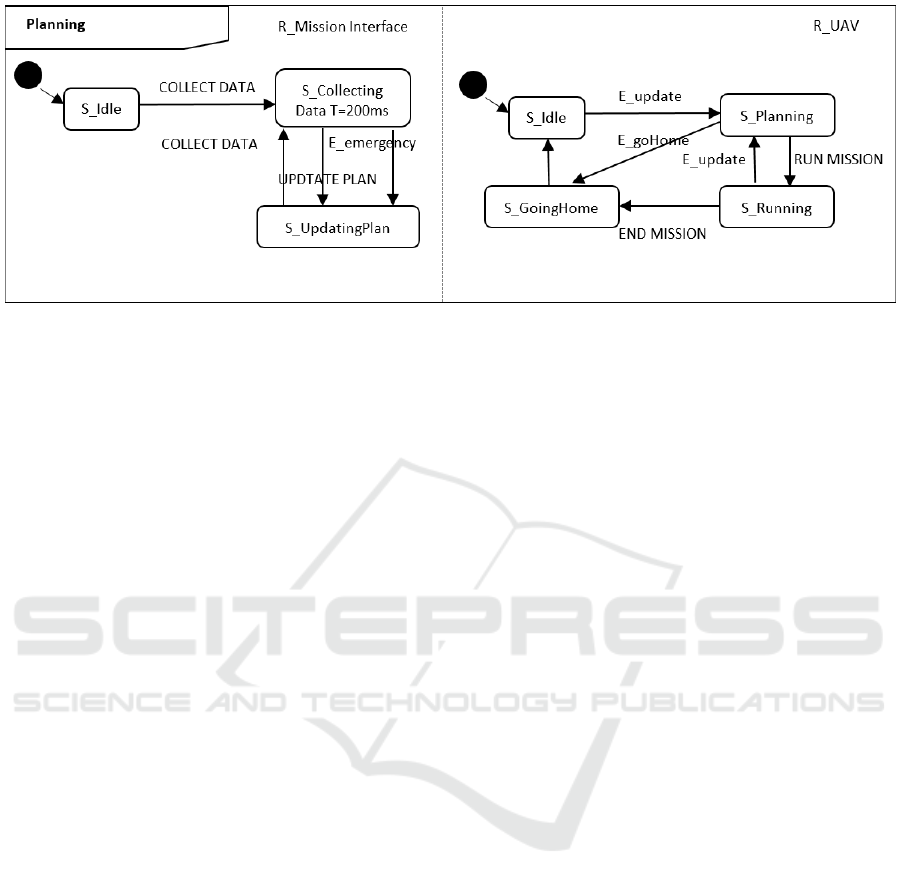
Figure 5: Choreography of the Planning contract.
6. Specify Choreography. This is one of the most
important steps in this new approach, since it
includes its main novelty, the use of state
machines instead of sequence diagrams. To
accomplish this step several sub-steps must be
taken:
a. A state machine will be created for each
defined contract.
b. A concurrent region of the state machine will
be implemented for each participant
involved in the contract. They will run in
parallel and in real time.
c. A state machine will be added to each
region, where interfaces involved in the
contract will correspond to transition events
that trigger state changes. Inside each state,
activities generating events can be run. In
Figure 5, the state machine corresponding to
the Planning Service Contract can be seen.
4 CONCLUSIONS
In this paper, we have proposed the combined use of
SOA, MDSD and CBSE and we have presented a
methodological guide that allows us to integrate the
SOA process in the C-Forge development process. In
this regard, the proposal of using state machines to
define the choreography is a feasible option to adapt
our component system to SOA in a simple way.
Future work includes developing a framework that
includes the research challenges discussed in this
paper (architectural modelling, mappings,
monitoring).
ACKNOWLEDGEMENTS
This research has been supported by the
MINECO/FEDER project grant TEC2016-76465-
C2-1-R (AIM), DGT (ref. SPIP2017-02286) and the
“Research Program for Groups of Scientific
Excellence in the Region of Murcia" of the Seneca
Foundation (Agency for Science and Technology in
the Region of Murcia – 19895/GERM/15), Spain.
REFERENCES
Ali, N., Babar, M. A., 2009. Modeling Service Oriented
Architectures of Mobile Applications by Extending
SoaML with Ambients, in: 2009 35th Euromicro
Conference on Software Engineering and Advanced
Applications.,
C-Forge | Eclipse-based model-driven tool-chain for
supporting a component-based development [WWW
Document], 2015. C-Forge. URL http://www.dsie.upct.
es/cforge/ (accessed 3.12.18).
Diego, A., Cristina, V.-C., Francisco, O., Juan, P., Bárbara,
Á., 2010. V3cmm: A 3-view component meta-model
for model-driven robotic software development.
J. Softw. Eng. Robot. 1, 3–17.
Erl, T., 2008. Soa: principles of service design. Prentice
Hall Upper Saddle River.
Ortiz, F. J., Insaurralde, C. C., Alonso, D., Sánchez, F.,
Petillot, Y. R., 2015. Model-driven analysis and design
for software development of autonomous underwater
vehicles. Robotica 33, 1731–1750. https://doi.org/
10.1017/S0263574714001027
Rosique, F., Alonso, D., Ortiz, F., 2016. Modeling and
Executing Component-based Applications in C-Forge,
in: 2016 11th International Conference on Software
Technologies (ICSOFT).
ICSOFT 2018 - 13th International Conference on Software Technologies
562
